Plasma arc welding (PAW) can produce deep, narrow, repeatable welds on steel tubes, but it is not a cure for poor fit-up or weak process control. The process works best when the tube seam, torch position, gas delivery, cooling, and travel speed stay inside a qualified window. This guide explains how PAW works, where it can outperform gas tungsten arc welding (GTAW), and what a tube mill must control before relying on keyhole welding in production.
Quick Answer
Plasma arc welding focuses a tungsten arc through a water-cooled nozzle, creating a stiff, high-energy plasma column. On suitable steel tube joints, keyhole PAW can make a single-pass, full-penetration seam with a narrow weld profile. Results still depend on qualified fit-up, gas flow, travel speed, torch condition, and inspection.
Key Takeaways
- PAW constricts a tungsten arc through a nozzle, giving it a narrower and stiffer energy column than conventional GTAW.
- Keyhole mode can produce single-pass, full-penetration welds on qualified tube joints, but wall thickness and material limits are equipment- and procedure-specific.
- A narrow arc does not remove the need for accurate seam tracking, edge alignment, root-gap control, clean surfaces, and stable cooling.
- Plasma gas, shielding gas, and backing or purge gas have different jobs and must be selected for the exact steel grade and service requirement.
- Automated tube mills gain the most value when PAW data, inspection results, nozzle life, and downtime are tracked together.
At a Glance
| Time Required | Expect several controlled trials for procedure development; production cycle time depends on tube size, wall thickness, welding mode, and line speed. |
| Difficulty | Advanced. PAW requires trained welding personnel, qualified procedures, controlled gas delivery, and disciplined torch maintenance. |
| Tools Needed | PAW power source and controller, water-cooled torch, plasma and shielding gas controls, cooling unit, fixtures, seam tracking or AVC as needed, and weld inspection equipment. |
| Cost | Usually higher than a basic GTAW setup. Judge the investment by qualified line speed, scrap rate, inspection yield, maintenance, training, and downtime. |
What’s in This Article
- How Plasma Arc Welding Works on Steel Tubes
- PAW Operating Modes
- Key Components of a PAW System for Tube Mills
- Why PAW Excels at Deep, Consistent Penetration
- Managing Heat Input and Minimizing Heat-Affected Zones
- Fit-Up, Root Gap, and Seam Tracking
- Comparing PAW to TIG for Tube Welding
- Plasma, Shielding, and Backing Gas Choices
- Qualifying a PAW Tube Welding Procedure
- Productivity Gains and Automation
- Quality, Inspection, and Distortion Control
- PAW Defects and Troubleshooting
- Maintenance, Training, and Safety
- When PAW May Not Be the Best Choice
- Frequently Asked Questions
- Sources
How Plasma Arc Welding Works on Steel Tubes
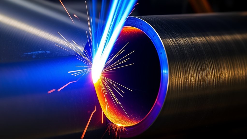
PAW uses a nonconsumable tungsten electrode, much like GTAW, but places the electrode inside a torch body behind a water-cooled constricting nozzle. Plasma gas passes through the small nozzle opening. The nozzle squeezes the arc into a narrow column and increases its energy density and directional stiffness.
Most transferred-arc PAW systems first create a low-current pilot arc between the tungsten electrode and the nozzle. The main arc then transfers from the electrode to the steel tube. This arrangement supports reliable mechanized starting and keeps high-frequency starting away from the work after the main arc is established.
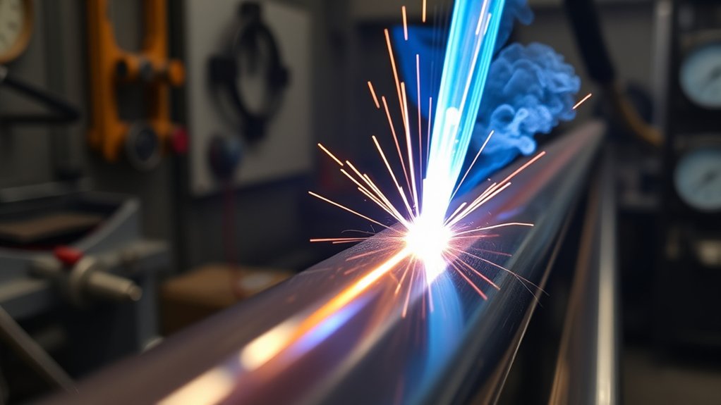
The focused plasma column can produce a narrow weld face and deep penetration. In keyhole mode, the plasma jet opens a small passage through the joint. Molten metal flows around that opening and closes behind the torch. The result can be a full-penetration seam from one side when the joint, material, wall thickness, position, and parameters are qualified.
The variables work as a system. Current affects melting and penetration. Plasma gas flow affects constriction and keyhole force. Shielding gas protects the top of the pool. Backing or purge gas protects the root when the material or service requires it. Travel speed, torch standoff, electrode setback, nozzle condition, and seam position determine whether the keyhole remains stable.
PAW’s advantage comes from controlled arc constriction—not from high current alone. A damaged nozzle, drifting seam, or unstable gas flow can erase that advantage quickly.
PAW Operating Modes
PAW is not one fixed process. The torch can run in several modes, and the correct mode depends on the tube wall, joint, and production goal.
| Mode | Typical Use | Main Control Concern |
|---|---|---|
| Microplasma | Very thin sheet, foil, wire, mesh, and small precision parts | Low-current stability, arc length, and heat concentration |
| Melt-in or soft plasma | Thin tube seams and joints that do not need a through-keyhole | Fusion depth, bead width, burn-through, and distortion |
| Keyhole plasma | Single-pass, full-penetration seams on suitable wall thicknesses | Keyhole opening, stability, closure, root profile, and fit-up |
Note: Published thickness capabilities are not universal settings. Torch design, nozzle size, material, position, joint design, and power-source controls change the usable range. Qualify the actual production tube instead of copying a catalog limit.
Key Components of a PAW System for Tube Mills
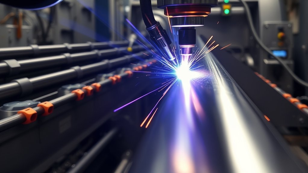
Precision starts with hardware that stays stable under production duty. A tube-mill PAW cell normally includes a constant-current power source, pilot-arc and sequence control, a water-cooled torch, a cooling unit, separate plasma and shielding gas circuits, fixtures, and motion control. Automated lines may also use arc-voltage control (AVC), seam tracking, backing gas control, data logging, and in-line inspection.
- Torch body and cooling: The cooling circuit protects the nozzle and helps hold a repeatable orifice temperature. Flow switches and over-temperature interlocks should stop the cycle before the torch is damaged.
- Constricting nozzle: Orifice diameter and geometry must match the qualified current and plasma flow. Erosion, contamination, or off-center wear can change arc shape and promote double arcing.
- Tungsten electrode: Electrode composition, diameter, tip geometry, setback, and grind direction affect starting and arc alignment. Grind marks should run along the electrode axis.
- Power source and sequence control: The system should control pilot arc, current ramp, main current, downslope, gas preflow, gas postflow, and keyhole closure.
- Gas delivery: Plasma, shielding, and backing gases need clean, dry lines and calibrated flow control. Interlocks should detect low pressure or loss of flow.
- Motion and tracking: Stable travel speed and seam position are essential. Long seams may benefit from AVC and seam tracking, especially as tungsten wear or tube wander changes torch-to-work distance.
Warning: Thoriated tungsten contains thorium. If a shop uses it, grinding dust and waste must be controlled under the employer’s radiation, ventilation, housekeeping, and disposal procedures. Ceriated or lanthanated electrodes may reduce that concern when the qualified process permits substitution.
Specify the system around duty cycle, tube outside diameter, wall thickness, material group, joint position, production speed, inspection requirement, and expected nozzle life. The equipment choice should follow the product requirement—not the other way around.
Products Worth Considering

APPLICATION: Apply to YESWELDER CUT-65DS/CUT-55DS PRO/CUT-55NHF/CUT-55NHF PLUS plasma cutters. Replacement for the S45 Plasma Cutting Torch.

AG60 Plasma Cutter Torch Body / Head compatible with standard of AG60 torch for 60A Plasma Cutting Machine. (i.e. CUT50, CUT60, CUT70.)

Wide Vision and Size: experience convenience with our welding glasses, measured at about 6.3 x 2.95 inches/ 16 x 7.5 cm (L x W), with a 180° viewing angle, you can enjoy the convenience of peripheral vision; The Shade 5 IR lens delivers a clear view, enhancing your performance and efficiency during various types and phases of welding
Why PAW Excels at Deep, Consistent Penetration
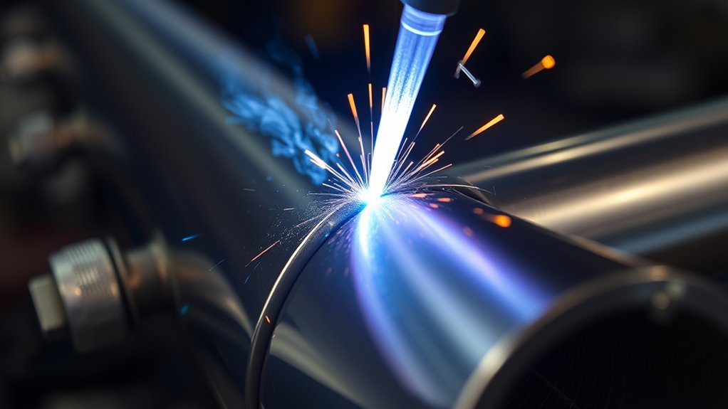
The constricting nozzle gives PAW a narrower, stiffer arc than conventional GTAW. In keyhole mode, the plasma jet and concentrated arc energy create a through-opening that moves with the torch. This mechanism can produce a high depth-to-width ratio and a full-penetration seam without a beveled groove on suitable tube walls.
That does not mean PAW always uses less current or always produces less total heat than GTAW. The result depends on voltage, current, travel speed, process efficiency, wall thickness, and whether GTAW would need several passes. PAW’s production advantage is strongest when it replaces edge beveling or multiple passes with one qualified seam.
Keyhole stability depends on:
- Consistent wall thickness and edge condition
- Controlled root opening and high-low alignment
- Correct electrode setback and torch standoff
- Stable plasma gas flow and nozzle geometry
- Steady travel speed and accurate seam tracking
- A controlled start, steady-state section, and keyhole closure sequence
| Production Measure | What It Reveals |
|---|---|
| Root penetration and internal reinforcement | Whether the keyhole is opening and closing at the intended depth |
| Face width and undercut | Whether heat distribution, tracking, and travel speed are stable |
| Current, voltage, and gas-flow trends | Whether the process is drifting before visible defects appear |
| Nozzle hours or arc-start count | Whether consumable wear correlates with penetration or scrap |
Managing Heat Input and Minimizing Heat-Affected Zones
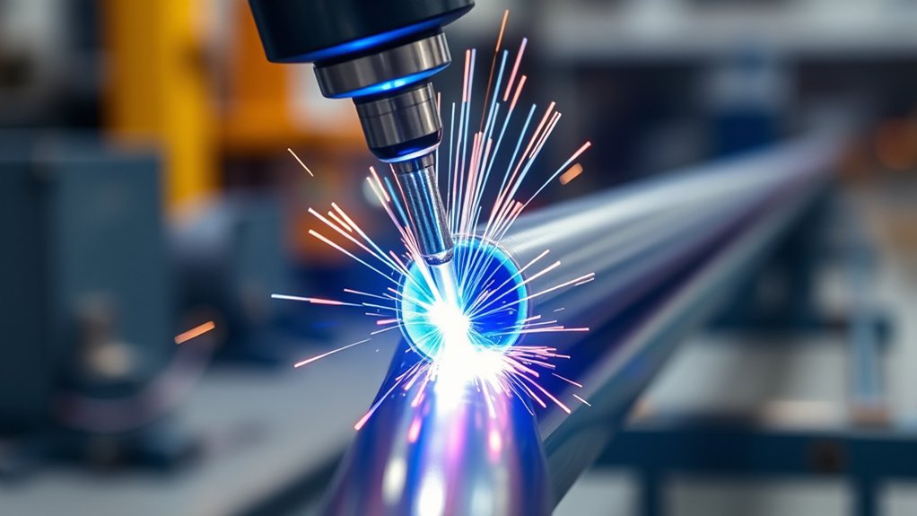
PAW concentrates energy into a narrow area, which can reduce bead width and heat-affected zone (HAZ) width compared with a wider or multi-pass process. The actual thermal cycle still depends on the measured welding parameters and the steel’s chemistry, thickness, preheat, restraint, and cooling conditions.
For constant-current welding, nominal arc energy per unit length can be estimated as:
Arc energy (kJ/mm) = voltage × current × 60 ÷ (1,000 × travel speed in mm/min)
This is an electrical-energy calculation. A code, customer specification, or engineering method may apply a process-efficiency factor to estimate heat delivered to the workpiece. Pulsed or complex waveforms may require integrated energy or power measurements instead of simple average current and voltage.
- Set current and plasma flow together: Enough energy and jet force are needed to hold the keyhole, but excessive settings can cause undercut, a wide root bead, burn-through, or nozzle damage.
- Keep travel speed steady: Slowing down raises energy per unit length. Speed variation can change penetration even when the current display looks stable.
- Control standoff: Torch height changes arc voltage and heat distribution. AVC can help on long automated seams, but it does not replace correct fixture alignment.
- Measure interpass or preheat when required: Carbon and low-alloy steels may need limits based on composition, thickness, hydrogen control, and the governing fabrication code.
- Verify the HAZ: Macro sections, hardness traverses, bend or tensile tests, and service-specific tests should confirm that the thermal cycle is acceptable.
Pro Tip: Log measured current, voltage, travel speed, plasma flow, shielding flow, standoff, nozzle ID, and inspection results under the same weld record. A single amperage setpoint cannot explain a changing root profile.
Fit-Up, Root Gap, and Seam Tracking
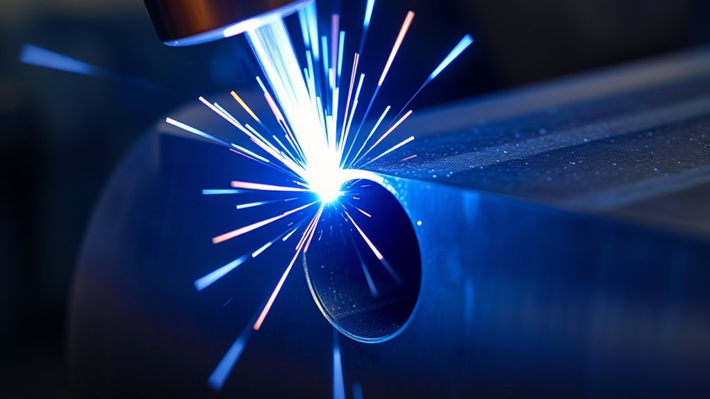
PAW can tolerate some qualified variation, but its narrow arc is not a general gap-bridging solution. Keyhole behavior changes when root opening, high-low misalignment, edge angle, wall thickness, or seam position changes. A face bead may look acceptable even while the root becomes too wide, too narrow, or incomplete.
Set production tolerances with procedure trials on the actual tube size. Include normal and worst-case conditions, such as minimum and maximum wall, expected edge mismatch, seam wander, and realistic line-speed variation. Record the resulting root profile and mechanical or nondestructive test results.
Consistent Edge Alignment
- Machine, shear, or form edges consistently enough to stay within the qualified joint geometry.
- Control high-low mismatch because one edge can block or deflect the keyhole.
- Use fixtures and squeeze rolls that hold the seam without creating changing restraint or ovality.
- Use seam tracking when tube wander can move the joint away from the plasma column.
- Check the root, not only the face, during setup and after any tooling change.
Gap-Bridging Limits
There is no safe universal root-gap number for PAW tube welding. The allowable gap depends on wall thickness, material, mode, filler addition, nozzle, current, plasma flow, travel speed, position, and acceptance criteria. Keyhole plasma may handle useful production variation, but it should be proven by coupon testing rather than assumed from arc stiffness.
Filler wire can help manage joint volume or chemistry in some procedures, but it also changes heat balance and pool behavior. Any change from autogenous to filler-assisted welding should be treated as a procedure variable and requalified when the governing code requires it.
Note: For a longitudinal seam, test the start, steady-state region, and stop. For a circumferential or orbital seam, also test changing positions and the keyhole-closure area.
Comparing PAW to TIG for Tube Welding
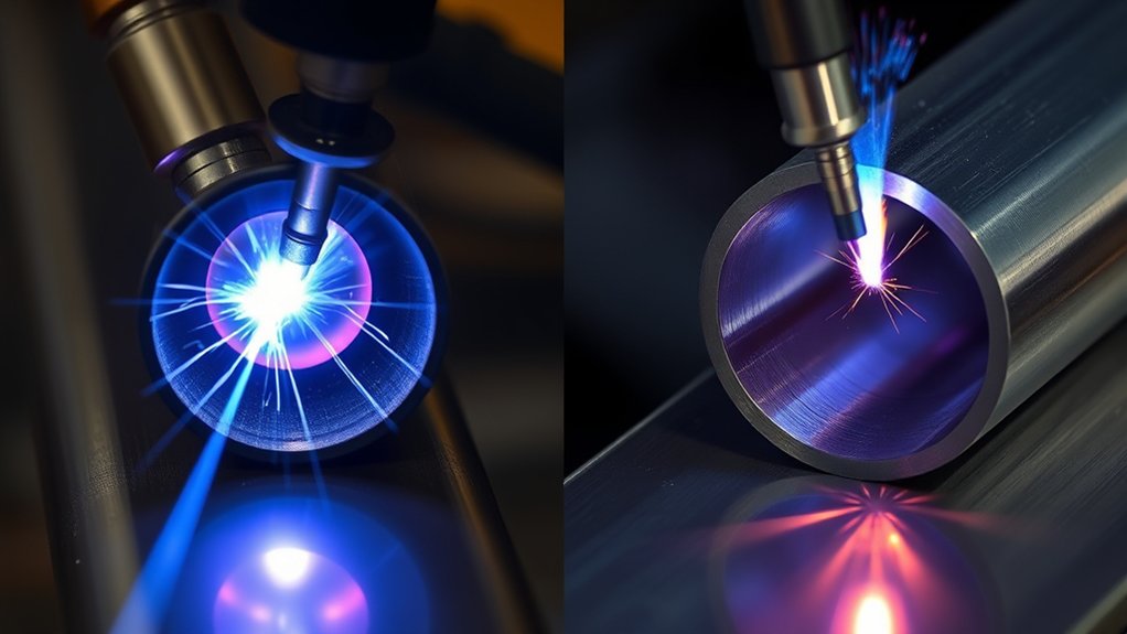
PAW and GTAW both use a tungsten electrode and can produce clean, high-quality welds. PAW adds a constricting nozzle, pilot arc, separate plasma gas, and tighter torch maintenance. GTAW is simpler and more familiar in many shops, while PAW offers a stiffer arc and keyhole capability for suitable mechanized seams.
| Factor | PAW | GTAW |
|---|---|---|
| Arc shape | Constricted, narrow, and stiff | Open and generally wider |
| Penetration | Deep and narrow in qualified keyhole mode | Excellent control; thicker joints may need a groove or more passes |
| Thin-wall control | Microplasma or melt-in mode can provide a stable concentrated arc | Strong manual and mechanized control with simpler torch hardware |
| Fit-up sensitivity | Requires a qualified gap, alignment, and tracking window | Also needs controlled fit-up; filler addition can improve flexibility |
| Automation | Strong fit for repeatable longitudinal or orbital production | Widely used for orbital and mechanized tube welding |
| Equipment and maintenance | More gas controls, cooling, nozzle wear, and setup discipline | Simpler torch and broader operator familiarity |
Choose PAW when a stable product family can benefit from single-pass penetration, high repeatability, or a narrow seam. Choose GTAW when flexibility, manual access, low volume, frequent joint changes, or simpler maintenance matters more.
Products Worth Considering

Powerful Flame Temperature Heat up to 5252°F (2900°C)

Extra-Long 13-FT Air Hose: Instead of moving the Argon welding cylinder tank all around, ARCCAPTAIN TIG Torch equipped with an extra-long 13-FT air hose and cables brings enormous convenience for distance welding. Meanwhile(furthermore), the cables are made of durable rubber hose with nylon over-braid, super-light, this innovative design makes the TIG welding torch keep(super) flexible under any circumstances.

High quality medium duty cutting torch CA1350 cutting attachment, 100FC torch handle.
Plasma, Shielding, and Backing Gas Choices
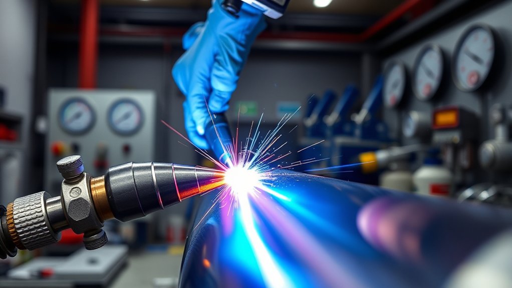
The plasma gas constricts and sustains the arc. The shielding gas protects the face of the weld pool and influences bead shape. A backing or purge gas protects the root when oxidation, corrosion resistance, or internal surface quality matters. These flows should be controlled and recorded separately.
Argon-Hydrogen Blends
Argon is widely used as a plasma gas because it supports stable starting and constriction. For some austenitic stainless steel procedures, an argon-based shielding or forming gas with a small hydrogen addition can increase heat transfer and improve wetting. The blend must match the material grade, carbon level, corrosion requirement, and applicable code.
Do not treat an argon-hydrogen blend as a universal stainless setting. Hydrogen-bearing gases can create cracking or metallurgical problems on ferritic, martensitic, duplex, precipitation-hardening, carbon, or low-alloy steels. Follow the gas supplier’s classification, the base-metal manufacturer’s guidance, and the qualified welding procedure.
Plasma, Shielding, and Backing Roles
- Plasma gas: Controls arc constriction, jet force, and keyhole behavior.
- Shielding gas: Protects the top of the molten pool and affects bead wetting and surface oxidation.
- Backing or purge gas: Protects the root and internal surface where the torch shield cannot reach.
Helium or helium-containing blends can increase arc voltage and heat transfer, but they also change nozzle loading, arc behavior, flow requirements, and keyhole stability. Use them only when procedure testing supports the change.
Flow Rates and Stability
Too little flow can weaken shielding or destabilize the keyhole. Too much flow can cause turbulence, pull air into the shield, disturb the pool, or accelerate nozzle wear. Set flows with calibrated equipment and verify actual delivery at the torch—not only regulator pressure.
- Leak-check hoses, fittings, torch seals, and the backing fixture.
- Confirm gas identity before connecting a cylinder or bulk supply.
- Record plasma, shielding, and backing flow as separate WPS variables.
- Audit flow at the start of a shift and after torch or cylinder changes.
- Use oxygen or dew-point checks when the product specification requires controlled root purity.
Warning: Argon, helium, and other shielding gases can displace oxygen. Confined or enclosed tube work requires a formal atmospheric, ventilation, entry, and rescue plan—not just a welding hood.
Qualifying a PAW Tube Welding Procedure
A production setting is not a qualified procedure until testing shows that it meets the governing construction code, customer specification, and service requirement. ISO 15614-1 covers qualification of welding procedures for steels and includes plasma arc welding. Pressure work may instead or additionally use the current edition of ASME BPVC Section IX, as required by the construction code.
- Define the application: Record steel grade, material group, tube diameter, wall range, joint design, position, service, and acceptance criteria.
- Set a preliminary WPS: Include PAW mode, polarity, current, voltage range, plasma flow, shielding flow, backing gas, travel speed, electrode, nozzle, standoff, setback, preheat, and filler details.
- Challenge the window: Test nominal settings plus realistic high and low limits for wall thickness, gap, alignment, speed, and gas flow.
- Test the weld: Use the required visual, dimensional, NDT, macro, bend, tensile, hardness, impact, corrosion, or other examinations.
- Document the PQR: Record actual variables, test results, acceptance, and the qualified range.
- Release production controls: Convert the qualified range into machine recipes, alarms, inspection frequency, maintenance limits, and traceable records.
For circumferential welding, qualify the start and keyhole-closure region. For a tube mill, test the effect of line starts, stops, coil changes, tooling changes, and expected seam wander. A steady coupon made under ideal conditions may not represent a full production shift.
Productivity Gains: Single-Pass Speed and Automation
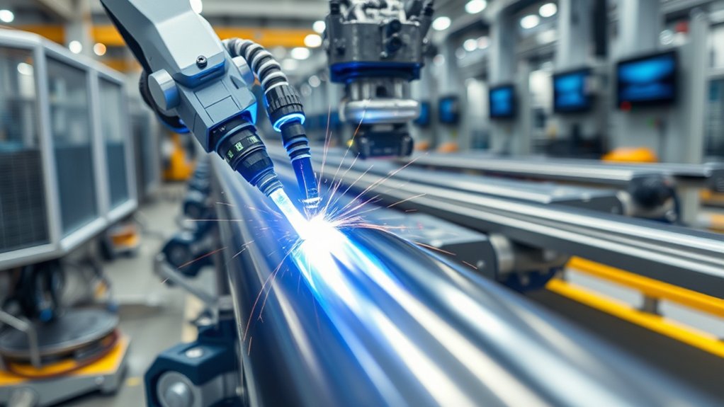
PAW can reduce cycle time when keyhole mode replaces bevel preparation, multiple passes, or slow travel with one qualified full-penetration pass. The benefit may include lower filler use, fewer starts and stops, less handling, and a narrower area that needs post-weld cleanup.
Automation strengthens those gains only when upstream and downstream systems are stable. Useful controls include:
- Programmable current and gas ramps
- AVC or torch-height control
- Optical, tactile, or through-arc seam tracking where suitable
- Cooling-flow, gas-pressure, and torch-temperature interlocks
- Actual-value logging for current, voltage, speed, and gas flow
- Recipe control tied to tube size and material
- In-line NDT synchronized to mill position
Track overall equipment effectiveness with weld quality, not speed alone. A faster line that consumes nozzles early, creates unstable root reinforcement, or raises false-reject rates may have a lower true output than a slower stable process.
Quality, Inspection, and Distortion Control on Thin-Walled Tubes
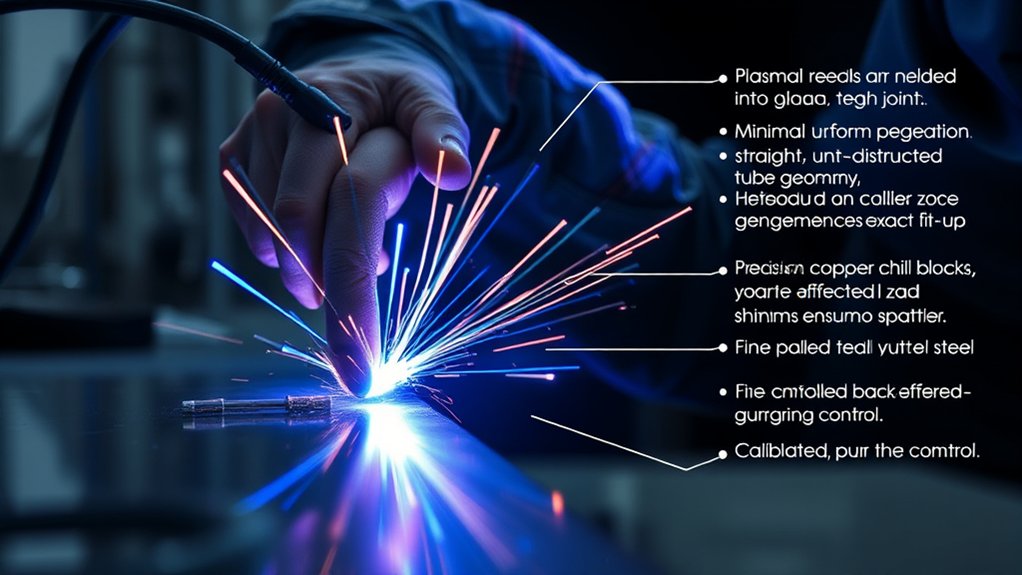
Thin-walled tubes respond quickly to excess energy, uneven restraint, and speed changes. PAW can help by concentrating the arc and limiting the number of passes, but distortion control still begins with forming accuracy, fixture balance, seam position, and a stable thermal cycle.
Inspect more than the face bead. A complete control plan may include:
- Face width, reinforcement, undercut, and surface oxidation
- Root penetration, root concavity or excess penetration, and internal oxidation
- Tube straightness, twist, ovality, and diameter after welding
- Macro sections during setup and after significant changes
- Eddy-current, ultrasonic, radiographic, leak, or other NDT selected for the product
- Mechanical and metallurgical tests required by the procedure or service
ISO 5817:2023 defines quality levels for imperfections in fusion-welded joints, while ISO 17635:2025 gives general rules for selecting and evaluating NDT methods. The applicable product or construction standard still determines the required quality level, test method, extent, and acceptance criteria.
A stable face bead is not proof of a stable keyhole. Root inspection and process data are essential whenever full penetration is the production objective.
PAW Defects and Troubleshooting
| Symptom | Likely Causes | Checks and Corrections |
|---|---|---|
| Incomplete penetration or lost keyhole | Low current, low plasma flow, high travel speed, excessive standoff, thick wall, seam offset, or worn nozzle | Verify actual current and flow, wall thickness, torch height, seam position, nozzle ID, and qualified speed |
| Burn-through or excessive root reinforcement | High energy per length, excessive plasma force, slow travel, large gap, or poor backing support | Check gap, speed, current, plasma flow, and root support against the WPS |
| Porosity | Oil, moisture, scale, coating, leaks, turbulent shielding, contaminated gas, or unstable keyhole closure | Clean to the qualified condition, leak-check the system, verify gas identity and flow, and inspect the closure sequence |
| Undercut or narrow face bead | High travel speed, excessive plasma force, seam offset, poor wetting, or incorrect shielding blend | Confirm tracking, speed, current-flow balance, and approved gas selection |
| Double arcing or rapid nozzle damage | Electrode or nozzle contamination, incorrect setback, too-small orifice for the current, low cooling, or excessive plasma flow | Stop the process, inspect the torch, verify cooling and setup dimensions, and replace damaged parts |
| Heavy heat tint or oxidized root | Poor shielding or purge, leaks, early gas shutoff, high oxygen level, or excessive heat | Verify preflow, postflow, backing seal, oxygen level where specified, and heat input |
Change one controlled variable at a time during troubleshooting. If several settings are adjusted together, the team may restore the weld without learning which condition caused the defect.
Maintenance, Training, and Safety Considerations
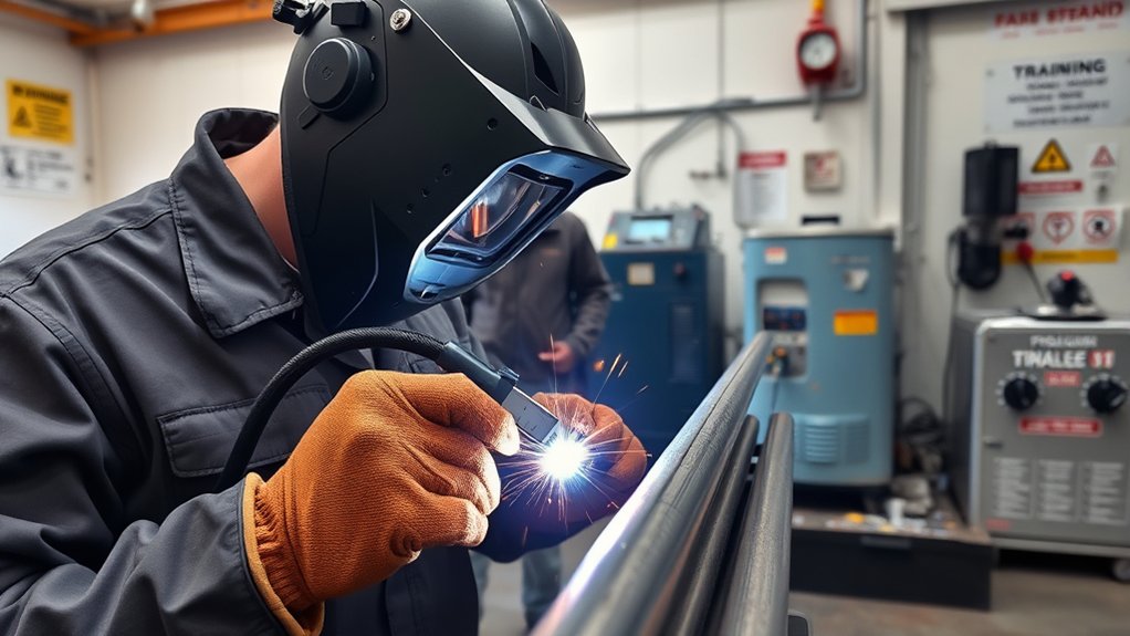
PAW keeps its precision only when the torch, cooling system, gas circuits, controls, and fixtures are maintained. Build preventive maintenance around measured wear rather than waiting for a visible defect.
- Each shift: Check cooling flow, leaks, gas identity, interlocks, cable condition, torch alignment, and shielding coverage.
- By arc-start count or run time: Inspect the electrode, nozzle, seals, collet, and orifice. Record replacements so nozzle life can be compared with weld quality.
- After a crash or double arc: Stop production and inspect the full torch stack before restarting.
- At scheduled intervals: Calibrate flow devices, current and voltage measurement, travel speed, AVC, and inspection equipment.
Operators and technicians should understand pilot-arc starting, transferred-arc behavior, keyhole opening and closure, gas roles, nozzle wear, double arcing, seam tracking, and the difference between a cosmetic face bead and acceptable root fusion.
PAW also creates the normal hazards of arc welding: electrical shock, intense ultraviolet and infrared radiation, hot metal, fire, compressed gas, fumes, gases, and moving machinery. OSHA’s welding hazard guidance identifies metal fumes, UV radiation, burns, eye damage, and electrical shock as major hazards. Use guarding, welding curtains, local exhaust ventilation, suitable PPE, lockout/tagout, and a written hot-work program.
Warning: Welding stainless steel can generate hexavalent chromium. Welding galvanized steel can generate zinc oxide fume and metal fume fever. Remove coatings when the procedure permits, capture fumes at the source, assess exposure, and use respiratory protection when engineering and work-practice controls do not reduce exposure adequately.
Do not use chlorinated solvents near the arc. UV energy and heat can break down some vapors into highly toxic gases. Confined-space welding requires atmospheric testing, ventilation, entry controls, and rescue planning under the applicable workplace rules.
When PAW May Not Be the Best Choice
PAW does not fit every tube job. GTAW, laser, high-frequency induction, resistance welding, or another process may provide better value depending on material, wall thickness, line speed, product mix, quality target, and capital budget.
PAW may be a weak choice when:
- Production volume is too low to recover procedure-development and equipment cost.
- Tube sizes, joints, and materials change too often for stable recipes.
- Fit-up, seam position, or wall thickness cannot be held inside a qualified window.
- The shop cannot support torch maintenance, cooling, calibrated gas delivery, or trained personnel.
- The service requires a metallurgy, filler system, heat treatment, or inspection plan better served by another process.
- Downtime risk from specialized components outweighs the cycle-time gain.
Build the business case from production trials. Compare acceptable tubes per hour, first-pass yield, edge-preparation cost, filler and gas use, nozzle life, inspection time, rework, training, planned maintenance, and unplanned downtime. PAW earns its place when the total cost per accepted tube improves—not merely when the travel speed rises.
Frequently Asked Questions
What tube joint designs work best for PAW?
Square-butt and narrow-groove butt joints are common when the goal is a stable keyhole and single-pass penetration. The root opening, land, edge angle, high-low alignment, and wall range must remain inside the qualified WPS. Circumferential joints also need a proven keyhole-closure sequence.
How does PAW handle galvanized or coated steel tubes?
Coatings can vaporize, disturb the keyhole, create porosity, contaminate the torch area, and produce hazardous fumes. Remove the coating from the weld zone when the engineering specification permits, provide source capture ventilation, qualify the cleaned joint, and restore corrosion protection after welding.
What surface preparation is required before PAW on tubes?
Prepare the joint to the condition used for qualification. Remove oil, moisture, loose scale, rust, paint, plating, and burrs from the weld zone. Keep edges dry, verify alignment, and prevent cleaning compounds or lint from remaining in the seam.
Can PAW integrate with in-line NDT for tube mills?
Yes. Eddy-current, ultrasonic, visual, leak, or other systems can be synchronized with mill speed and encoder position. The selected method must suit the material, wall thickness, defect types, product standard, and required acceptance level. Store inspection results with the related process data for traceability.
How does PAW affect internal bead shape for flow applications?
A stable PAW procedure can produce a controlled, relatively narrow internal bead, but the result depends on keyhole force, root gap, backing gas, travel speed, and closure. Validate the internal profile by sectioning, profilometry, borescope inspection, or the method required by the product specification.
Is PAW always faster than TIG welding?
No. PAW can be faster when keyhole mode replaces a bevel or several GTAW passes, but setup, qualification, nozzle changes, inspection, and downtime affect total output. GTAW may be more efficient for low-volume, frequently changing, or manually accessed work.
What is the most important PAW parameter?
There is no single most important setting. Current, voltage, plasma flow, shielding flow, travel speed, standoff, electrode setback, nozzle geometry, joint fit-up, and seam position interact. Control the full qualified window and monitor actual values rather than relying on one setpoint.
Conclusion
PAW can turn a stable steel tube seam into a fast, repeatable, full-penetration production weld. Its value comes from a constricted arc, disciplined gas control, accurate fit-up, reliable cooling, and a qualified keyhole sequence. Prove the process on real tube sizes and realistic variation, then track root quality, inspection yield, nozzle life, and downtime. When those measures improve together, PAW can outperform GTAW on the right tube product. When they do not, a simpler process may deliver better total value.
Sources
- Fronius Welding Wiki: Plasma Welding — constricted-arc operation, PAW modes, penetration, and comparison with TIG.
- ISO 15614-1:2017 — procedure qualification for arc and gas welding of steels, including plasma arc welding.
- ISO 14175:2008 — classification of gases and gas mixtures used in fusion welding and allied processes.
- ISO 5817:2023 — quality levels for imperfections in fusion-welded joints.
- ISO 17635:2025 — general rules for selecting and evaluating nondestructive testing of metallic welds.
- OSHA Welding, Cutting, and Brazing Hazards and Solutions — controls for fumes, radiation, burns, electrical shock, and related welding hazards.