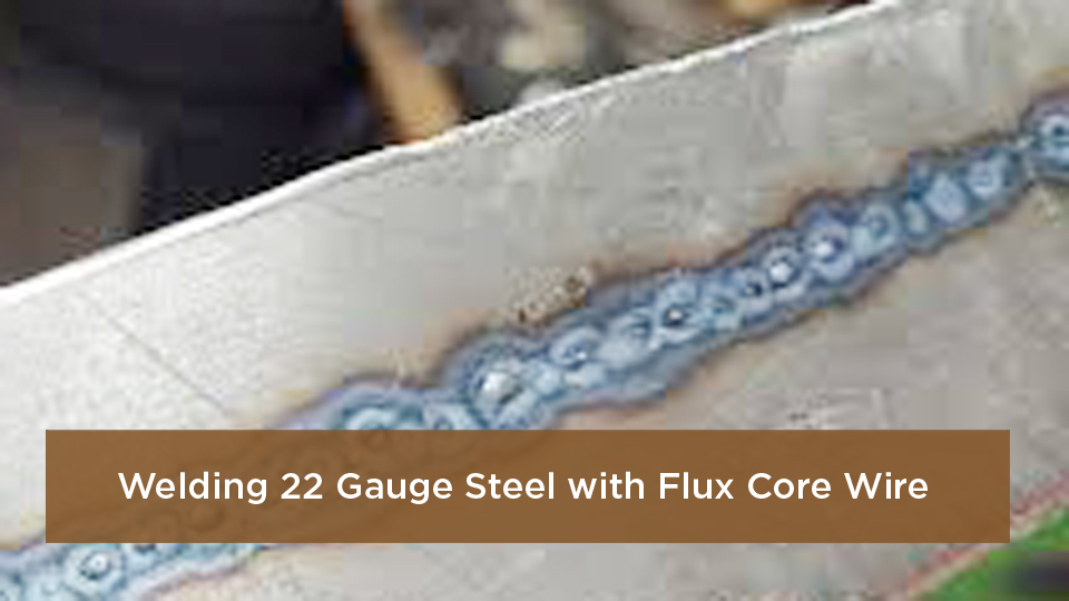
Welding a steel car body panel with self-shielded flux-core wire is possible, but thin sheet metal gives you very little room for error. Too much heat, a wide joint gap, incorrect polarity, or a long weld can quickly leave you with holes and a warped panel. I learned that on my first rusty fender patch when the wire fed smoothly but the panel disappeared around the weld. The practical solution is careful preparation, test welds, and a series of widely spaced trigger tacks rather than continuous beads.
Last updated: July 20, 2026
Quick Answer
You can weld thin steel body panels with self-shielded flux-core wire, but it is less forgiving than gas-shielded MIG. Use 0.030-inch wire approved for your machine, correct polarity, clean fit-up, and widely spaced trigger tacks instead of continuous beads. Follow the vehicle maker’s repair procedure for structural or late-model panels.

Image by speedwaymotors
Key Takeaways
- Use flux core only where the vehicle maker permits the process. Do not assume it is suitable for pillars, rails, reinforcements, crush structures, or other structural parts.
- A quality 0.030-inch self-shielded wire is a practical starting point for older mild-steel cosmetic panels, but the spool label and machine chart control the final setup.
- Clean both sides of the joint, keep the fit even, and practice on matching scrap before touching the vehicle.
- Build the seam from isolated trigger tacks. Do not start with one-inch welds on thin outer-skin panels.
- Inspect the backside, remove slag between welds, avoid overgrinding, and restore primer, seam sealer, and cavity protection after welding.
At a Glance
| Time Required | Several hours for a small patch, including fitting, cooling, grinding, inspection, and corrosion protection |
| Difficulty | Intermediate; thin exterior skins are less forgiving than floor pans or thicker brackets |
| Tools Needed | Flux-core-capable welder, approved wire, helmet, safety glasses, gloves, flame-resistant clothing, grinder, wire brush, clamps, copper backing, welding blanket, and fire extinguisher |
| Cost | Low to moderate if you already own the welder and PPE; substantially higher if you need equipment or professional structural repair |
Warning: This guide is for non-structural patching on weldable steel where flux-core welding is permitted. Before touching a late-model vehicle, check its body repair manual. Do not use this article as approval to weld a frame rail, pillar, rocker reinforcement, suspension mount, crush structure, battery enclosure, or high-strength structural component.
Know When Flux Core Is Appropriate
Flux core is most practical for small repairs on older mild-steel panels, floor sections, utility vehicles, and non-structural patches where shielding gas would be inconvenient. It is not automatically an approved collision-repair process simply because the finished weld feels strong.
Modern vehicles may combine mild steel, galvanized steel, high-strength steel, ultra-high-strength steel, aluminum, adhesives, rivets, spot welds, and MIG-brazed joints in the same body. Heating the wrong area can reduce strength or change the way the vehicle manages crash energy. The I-CAR overview of modern collision-repair attachment methods explains why the vehicle maker’s procedure must control the process, wire, joint location, and equipment.
Identify the Panel Before Welding
- Confirm that the panel is steel rather than aluminum.
- Check the vehicle repair manual for the steel grade and approved attachment method.
- Measure the removed section or matching scrap with a sheet-metal gauge or caliper.
- Inspect both sides for galvanizing, paint, seam sealer, undercoating, adhesive, lead filler, or previous repairs.
- Stop if rust extends into a reinforcement, mounting point, or area that cannot be restored to the original repair specification.
Note: A floor pan can still be structural or safety-related depending on the vehicle and location. “Not visible” does not mean “non-structural.”
Why Use Flux Core for Body Panels?
Self-shielded flux-core welding creates shielding from compounds inside the wire, so you do not need a gas cylinder. That makes the equipment portable and more tolerant of outdoor air movement than gas-shielded MIG. My first flux-core welder was a small 110-volt unit, and it let me patch an old truck’s rocker skin without buying a regulator and cylinder.
The tradeoff is heat and cleanup. Self-shielded wire normally creates slag and more spatter than solid-wire MIG. It can also be harder to control on very thin panels. Miller’s flux-core welding guide notes that slag must be removed and that many operators choose MIG when appearance and cleanup are priorities.
Flux core is more tolerant of minor surface contamination than gas-shielded MIG, but that does not mean you should weld over rust, paint, undercoating, or seam sealer. Clean steel still produces the most reliable result.
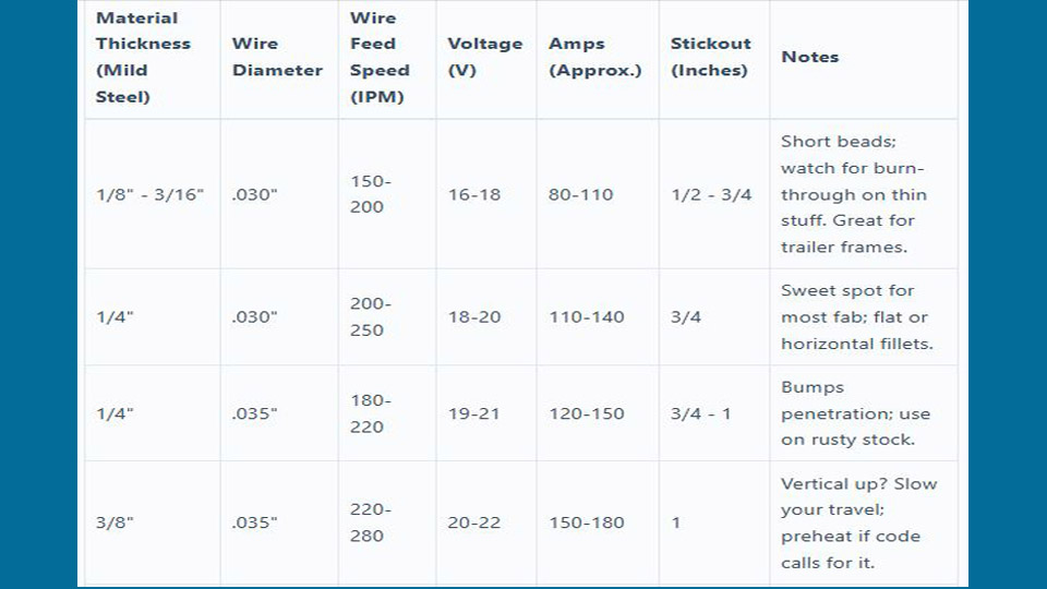
For DIY work, its main benefits are portability, simple setup, and resistance to moderate wind. Its main disadvantages are a hotter, less forgiving arc on thin sheet, extra slag, more spatter, and a higher risk of visible distortion. For a separate machine-setting reference, see the flux core MIG settings chart, then verify every setting against your wire and welder manuals.
Tools and Materials You’ll Need
- A DC wire-feed welder approved for the selected self-shielded wire
- 0.030-inch self-shielded flux-core wire approved for your machine and panel thickness
- The matching contact tip and the drive roll recommended by the welder manufacturer
- A welding helmet, safety glasses, hearing protection, leather gloves, flame-resistant clothing, and leather footwear
- A grinder or sander with suitable discs, plus a dedicated carbon-steel wire brush
- Sheet-metal shears, aviation snips, a body saw, or another controlled cutting tool
- Panel clamps, locking pliers, magnets used away from the active arc, and a straightedge
- A clean copper backing bar or flattened copper pipe for accessible butt joints
- A non-chlorinated, residue-free cleaner that is compatible with the metal and coatings
- Welding blankets, noncombustible shields, a suitable fire extinguisher, and adequate local exhaust
- Matching scrap steel for setup and destructive test welds
- Approved primer, seam sealer, topcoat, and cavity-protection materials for the finished repair
Products Worth Considering

E71T-GS FLUX CORE WIRE: This self-shielding, AWS E71T-GS flux-cored wire excels due to its advanced core design, delivering exceptional arc stabilization and high feedability for effortless welding. The core also incorporates powerful deoxidizing agents, ensuring clean, reliable welds even when welding through light rust or mill scale.

Welding Easy and Quick: AWS E71T-GS 030” Flux Core welding wire (The actual Net Weight of Wire is 2LB), no need for shielding gas, install it then you can welding all positions, single and multi pass welding. Great for T-joints, butt welds & lap welds.

Effortless and Efficient Welding: Hassle-free experience with our AWS E71T-GS 0.030" Flux Core welding wire (Net Weight: 10lbs). No shielding gas needed, install and weld in any position. Perfect for strong T-joints, butt welds, and lap welds.
Choosing the Right Flux-Core Welder
For auto-body work, low-end control matters more than the maximum amperage printed on the box. You need a machine that can maintain a stable arc at the lowest settings required by your wire and test coupon. Adjustable voltage and wire feed are easier to tune than a machine with only one or two coarse heat selections.
Many small 90- to 140-amp machines can run 0.030-inch self-shielded wire. Examples include the Hobart Handler 140, YesWelder 135, and Eastwood MP140i. These are examples, not automatic recommendations for a particular vehicle. Check the machine’s minimum output, supported wire, polarity arrangement, chart, electrical requirements, and available service before choosing one.
Confirm that the machine can accept the correct contact tip and drive roll. Flux-core wire is softer than solid wire, and many machines specify a knurled drive roll. Excessive drive-roll tension can crush the wire, while too little tension causes slipping and an unstable arc.
Duty cycle is less important on a body-panel seam than it is during continuous fabrication because you should already be pausing between tacks. Stable low-output control, consistent feeding, and easily changed polarity are more valuable for this job.
Products Worth Considering
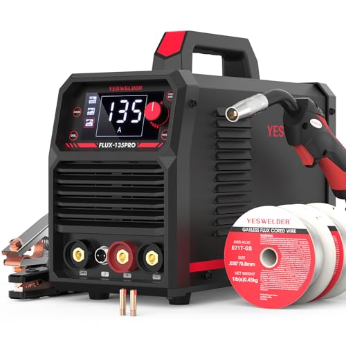
READY OUT OF THE BOX: Start welding immediately! It masterfully handles Gasless Flux Core MIG, Stick, and Lift TIG (Extra Lift TIG torch required). This budget-friendly 3-in-1 machine includes extra E71T-GS .030''&.035'' flux core wires, known for its smooth arc and high feedability. Say goodbye to heavy shielding gas cylinders—perfect for outdoor, windy, or all-position welding.

5-in-1 covers all your welding needs — from thin sheet metal to thick steel. Pulse mode delivers smoother MIG welds with less spatter. SPOT welding handles auto body panels without burn-through. Synergic control auto-matches current to wire speed — no more guesswork. One machine replaces three, saves $400+ on tool costs

Compatible Welder Models: this compatible with KP1939-1 replacement kit is designed for use with 170A flux core welders; Before ordering, please confirm your welder uses the KP1939-1 nozzle interface by checking your welder manual or comparing the nozzle size with our product images
Choosing Flux-Core Wire for Thin Body Panels
A quality 0.030-inch self-shielded wire is a reasonable starting point for thin mild-steel repairs. E71T-GS is commonly sold for single-pass sheet-metal and repair work, but products carrying that classification do not all have identical operating characteristics. Read the specific spool label and technical data sheet rather than relying only on the classification.
E71T-11 is another common self-shielded wire. It can support broader fabrication work and may allow multiple passes within the product’s limits, but that does not automatically make it better for a 20- or 22-gauge exterior skin. The exact wire, machine, joint, and panel thickness must work together.
A 0.035-inch wire generally requires more heat and is harder to manage on very thin body sheet. Use it only when the wire and machine charts support the metal thickness and your test coupon proves that you can achieve fusion without repeated burn-through.
Store flux-core wire in a clean, dry location. Replace rusty, dirty, kinked, or moisture-damaged wire. Inconsistent diameter, damaged flux, or poor winding can create feeding problems, unstable output, and porosity.
Pro Tip: Keep offcuts from the actual patch panel. They give you a better setup coupon than a random piece of thicker shop steel.
Setting Up Your Welder for Thin Sheet Metal
Thin sheet will expose every setup error. Before testing settings, inspect the gun liner, contact tip, cable connections, work lead, drive roll, spool tension, and wire condition. Attach the work clamp to clean bare metal as close to the repair as practical without placing it on a component that could be damaged by current flow.
Set the Correct Polarity
Most small self-shielded E71T-GS and E71T-11 wires use DC electrode negative, commonly written as DCEN. That normally means the gun is connected to negative and the work lead to positive. However, polarity is a consumable requirement, not a rule you should apply blindly. Confirm it on the spool label or wire datasheet before welding.
Use the Wire Manufacturer’s Stick-Out
Flux-core wire generally uses a longer electrode extension than solid-wire MIG. Miller gives approximately 3/4 inch as a general FCAW starting point, but your exact wire may specify a different value. Hold the extension consistently and measure from the contact tip, not from the end of a decorative gas nozzle.
Do not force every thin-panel job to run at 1/4-inch stick-out. An extension that is far outside the wire manufacturer’s range can change current, arc stability, penetration, and spatter.
Quick Starting-Point Guide
| Panel Thickness | Machine Starting Point | Welding Method | How to Verify |
|---|---|---|---|
| 18–20 gauge | Use the machine chart for the exact wire, then begin near the low end of the listed range | Separated trigger tacks; only use a very short stitch after coupon testing proves it is safe | Inspect bead profile, fusion, backside heat evidence, and a destructive test coupon |
| 20–22 gauge | Use the lowest stable chart setting that still fuses the joint | Brief trigger tacks with long cooling intervals; use copper backing where accessible | Reject settings that create pinholes, ropey deposits, edge melting, or easy weld separation |
There is no universal voltage and wire-feed number for every welder. Two machines displaying the same voltage can behave differently, and E71T-GS products from different manufacturers can have different operating windows.
Test on Matching Scrap
- Clean two offcuts exactly as you will clean the repair.
- Reproduce the same joint, gap, position, and backing.
- Start with the machine chart for the exact wire and thickness.
- Make several separated tacks.
- Remove all slag and inspect for undercut, pinholes, overlap, and incomplete fusion.
- Bend, twist, or hammer the coupon. The surrounding sheet should deform before a properly fused tack simply falls off.
- Adjust one control or technique variable at a time.
Preparing the Vehicle and Panels
Good welds start with preparation, but preparation on a vehicle means more than cleaning the visible side. You must inspect and protect everything behind, below, and beside the repair.
Make the Vehicle Safe for Hot Work
- Read the vehicle maker’s welding, battery-disconnection, restraint-system, and corrosion-protection procedures.
- For a hybrid or electric vehicle, do not begin until the high-voltage system has been disabled and verified by someone trained for that vehicle.
- Protect or remove wiring, electronic modules, fuel lines, brake lines, hoses, glass, trim, carpet, insulation, seam sealer, and sound-deadening material near the repair.
- Inspect enclosed cavities for foam, wax, adhesive, and previous repairs.
- Shield the opposite side with a noncombustible welding blanket where appropriate.
- Keep a suitable fire extinguisher within reach and arrange a second person as a fire watch when hidden material could ignite.
- Continue checking the repair and opposite side for smoldering material after welding is complete.
Warning: Never weld near an unprotected fuel system, battery, airbag component, pyrotechnic seat-belt device, pressurized line, or energized high-voltage circuit. Do not weld a tank, closed section, or container that may hold flammable vapor.
Remove Contamination on Both Sides
Grind or sand the immediate weld area to clean, sound metal. Remove rust, paint, primer, undercoating, seam sealer, adhesive, grease, and scale from both sides wherever you can reach them. Clean the area used by the work clamp as well.
Use a compatible, residue-free, non-chlorinated cleaner and allow it to evaporate completely before striking an arc. Never use chlorinated brake cleaner, chlorinated paint remover, or an unknown solvent near welding. Heat and ultraviolet radiation can break down chlorinated hydrocarbons and create highly toxic gases. See the CDC phosgene safety guidance.
Fit the Patch Accurately
Cut back to solid metal. A patch welded onto thin, deeply pitted steel will not create a durable repair. Shape the replacement so it follows the original contour without being forced into place by heavy clamp pressure.
For a butt joint, keep the edges square, clean, and evenly fitted. Do not bevel thin body sheet as a default. The acceptable gap depends on the wire, panel thickness, and technique, but a large or inconsistent opening makes burn-through much more likely.
Use sheet-metal clamps, locking pliers, or suitable magnets to hold the patch flush. Place the first locating tacks far apart, check alignment, and correct the fit before adding more welds.
Use Weld-Through Primer Only Where Approved
Weld-through primer is intended for certain enclosed mating flanges, not as a substitute for clean metal in the active weld zone. Vehicle makers differ on where it is allowed. The I-CAR weld-through primer guidance shows why you must check the OEM procedure and coating instructions before applying it.
If the procedure permits a conductive weld-through coating, apply only the specified amount to the approved mating surfaces. Keep the direct fusion area as clean as the process requires. After welding, restore the vehicle maker’s normal primer, seam sealer, topcoat, and cavity-protection system.
Joint Types for Body Panels
Butt Joints
A close-fitting butt joint is often the best option for a visible cosmetic patch because both surfaces can remain nearly flush. It also avoids leaving a moisture-trapping overlap. The downside is that the open edge has little mass, so fit-up and heat control must be excellent.
Keep thin-sheet edges square. A bevel removes valuable metal and usually increases burn-through risk. Use copper backing where the backside is accessible, but do not depend on the copper to correct a wide, poorly fitted gap.
Lap Joints
A lap joint can be useful on a hidden repair, flange, floor section, or design that originally used an overlap. It is easier to clamp and gives the arc more material to work with. However, the overlap can create a visible step and a corrosion pocket unless it is sealed and protected correctly.
Do not create a lap joint merely because it feels easier. Follow the original construction or the vehicle-specific repair method.
Plug Welds
A plug weld joins an upper sheet to a lower flange through a prepared hole. It is not simply a tack placed in a random drilled opening. Hole diameter, spacing, flange width, coating, weld sequence, and required nugget size may be specified by the vehicle maker.
Clean both mating surfaces, clamp the sheets tightly, aim the wire at the lower panel first, and fill the hole outward until the weld fuses around the full perimeter. Practice on a matching two-layer coupon and peel-test the sample before using the technique on the vehicle. I used plug welds on an old Jeep floor repair, but I still copied the original flange layout rather than guessing the spacing.
Flux-Core Technique for Avoiding Burn-Through
Heat control is the central skill. The biggest mistake I made early on was trying to run a visible bead. On thin body sheet, the seam should normally be built from separate trigger tacks rather than one continuous pass.
Use Spaced Trigger Tacks
- Place the first locating tacks at widely separated points.
- Confirm that the patch remains flush and the surrounding panel has not pulled out of shape.
- Add new tacks midway between cool existing tacks.
- Move to a distant area after every tack instead of welding the neighboring spot immediately.
- Remove slag before placing a tack against a previous weld.
- Continue dividing the open spaces until the seam is closed.
Each trigger pull should be only long enough to establish fusion and fill the local joint. The correct duration depends on the welder, wire, panel, gap, and position. Do not treat a one-inch weld as the default starting point for 20- or 22-gauge exterior sheet.
Use the Correct Gun Angle
Use a drag or pull technique with the gun aimed back toward the weld pool. A travel angle of roughly 5 to 15 degrees is a sound general range. Extreme angles can increase spatter, reduce penetration, and make the arc unstable.
Keep the work angle centered on a butt joint. On a lap or plug weld, direct the arc so both sheets fuse rather than depositing wire only on the upper edge.
Keep Stick-Out Consistent
Use the extension specified by the wire manufacturer. Many self-shielded wires run with a longer extension than solid-wire MIG, often around 1/2 to 3/4 inch. A changing extension changes how the wire burns and makes it harder to repeat a successful tack.
Use Copper Backing Carefully
A clean copper backing bar can support the molten pool, absorb some heat, and help close a small hole because steel weld metal does not readily fuse to the copper. I have used flattened copper pipe when access was limited.
Hold the backing firmly against the backside. Remove paint, adhesive, and contamination first. Copper backing will not make a structurally unsuitable repair acceptable, and it will not fix severely thinned or inaccessible rust damage.
Pro Tip: Mark several distant starting zones around a large patch with a paint marker. Rotating among those zones makes it easier to avoid concentrating heat in one corner.
Stop at the First Sign of Distortion
Check the panel with a straightedge and your hand after each group of tacks. If the panel begins to crown, oil-can, or pull inward, stop and allow it to cool naturally. Do not keep welding in an attempt to “finish the section.”
A hammer and dolly can correct minor distortion, but careless hammering stretches thin sheet and can make the problem worse. Let the panel cool and use controlled metal-finishing techniques rather than striking a hot, unsupported panel.
Managing Slag, Spatter, and Grinding
Self-shielded flux core leaves slag over the weld. Remove it with a wire brush or small chipping tool before welding onto or beside an existing tack. Trapped slag can prevent fusion and create inclusions or pinholes.
If spatter suddenly increases, check polarity, work-clamp contact, contact-tip condition, stick-out, gun angle, wire feeding, and machine settings. I once chased a spatter problem until I noticed that the work clamp was attached over paint. Cleaning a bare contact point fixed the unstable circuit.
Anti-spatter products can help protect the nozzle, but keep sprays and gels out of the joint and away from surfaces that must later accept primer or paint. Use the smallest amount needed and follow the product instructions.
For a visible repair, grind in short sessions with light pressure. A 60- or 80-grit flap disc or a controlled body-file system is often easier to manage than an aggressive hard wheel. Stop as soon as the weld is level with the surrounding metal. Grinding the bead below the panel surface weakens the joint and thins the sheet.
Note: A perfectly smooth front surface does not prove that the backside is fused. Inspect both sides whenever access allows.
Safety: Protect Yourself and the Vehicle
Flux-core welding produces ultraviolet radiation, hot slag, spatter, fumes, and hidden fire hazards. Wear a welding helmet, safety glasses under the helmet, leather gloves, flame-resistant long sleeves, cuffless pants, and leather footwear. A spark that lands in a shoe or folded cuff can stay hot long enough to cause a serious burn.
Select the Helmet Shade by Current
Use a helmet and lens that meet the applicable safety standard and follow the helmet instructions. Under OSHA’s general-industry table, the minimum protective shade for GMAW and FCAW is shade 7 below 60 amps and shade 10 from 60 to 160 amps. Start with a darker setting and move lighter only until you can clearly see the joint without eye discomfort. See OSHA 29 CFR 1910.133.
Control Welding Fumes
Use local exhaust that captures fumes near the arc and moves them away from your breathing zone. Opening a garage door may help, but it is not a substitute for effective fume control when coatings, galvanized steel, enclosed spaces, or substantial welding are involved.
Keep your head out of the plume. Do not direct airflow in a way that pushes fumes toward another person or stirs contamination through the shop. A respirator may be necessary after a proper hazard assessment, but it must be suitable for the contaminant, fitted correctly, and used according to its instructions. Review OSHA’s welding, cutting, and brazing requirements and the AWS Ventilation Guide for Weld Fume.
Treat Galvanized and Coated Steel as a Fume Hazard
Many vehicle panels are zinc-coated. Identify the coating before grinding or welding and follow the OEM repair procedure. Indoor welding involving zinc-bearing coatings requires effective ventilation controls. Remove only the coating the approved repair requires, capture fumes near the source, and restore corrosion protection afterward.
Maintain a Fire Watch
Sparks can enter a rocker, pillar, floor cavity, or trim gap and ignite material you cannot see. Inspect the opposite side during the work and continue checking after the last weld. OSHA workplace rules call for a fire watch to continue for at least 30 minutes in situations where one is required. Applying the same cautious practice in a home garage can catch smoldering seam sealer, insulation, or sound deadener before it becomes a fire.
If you are unsure whether your wire needs external gas, see Does flux core welding require gas?
Step-by-Step Guide to Welding a Body-Panel Patch
- Confirm the repair method. Identify the vehicle, panel material, steel grade, and whether the area is structural. Check the body repair manual before cutting.
- Make the vehicle safe. Follow the OEM electrical and restraint-system procedures. Protect fuel and brake lines, wiring, glass, trim, upholstery, insulation, electronics, and the opposite side of the repair. Arrange ventilation and fire protection.
- Cut back to solid metal. Remove all deeply pitted or perforated steel. Do not weld a patch over metal that is too thin to support fusion.
- Shape and fit the patch. Match the original contour and use the joint type required by the repair. Keep butt-joint edges square and evenly fitted.
- Clean both sides. Remove paint, rust, seam sealer, adhesive, coatings, grease, and undercoating from the active weld area. Use only a compatible non-chlorinated cleaner and let it evaporate completely.
- Set up the welder. Install the correct drive roll, contact tip, and wire. Set the polarity shown on the spool label, adjust tension, and use the recommended stick-out.
- Make test welds. Reproduce the joint on matching scrap. Adjust the machine and technique until the coupon shows fusion without excessive burn-through or distortion.
- Place locating tacks. Clamp the panel flush and add widely separated tacks. Recheck contour and alignment before adding more.
- Close the seam gradually. Add new tacks between fully cooled welds while moving around the panel. Remove slag before overlapping or adjoining a previous tack. Use copper backing where suitable and accessible.
- Inspect the repair. Look for pinholes, cracks, slag inclusions, undercut, cold overlap, missed areas, and excessive distortion. Inspect the backside whenever possible.
- Dress the weld carefully. Remove slag and grind only until the repair is level. Avoid thinning the panel or cutting below the surrounding surface.
- Restore corrosion protection. Clean the repair and apply the approved primer, seam sealer, topcoat, and backside cavity protection. Replace any removed insulation or trim only after the area is cool and the fire watch is complete.
This general sequence has worked for me on cosmetic fender patches and older floor repairs, but the vehicle maker’s procedure always takes priority over a general technique.
How to Check Weld Quality
Appearance alone is not enough. Before working on the vehicle, make a joint on matching scrap and test it destructively. Bend, twist, or peel the coupon. A sound plug weld should tear or pull material from the surrounding sheet rather than popping cleanly away. A butt-joint tack should remain fused while the adjacent sheet deforms.
On the completed repair, check for:
- Continuous fusion with no open pinholes
- No visible cracks or slag trapped between tacks
- No cold, rope-like deposits sitting on top of the sheet
- No severe undercut or melted-away panel edge
- No excessive grinding below the original panel surface
- No uncontrolled distortion or change in adjacent body gaps
- Complete corrosion protection on accessible front and rear surfaces
For a required OEM plug-weld or structural joint, use the vehicle maker’s weld-size, spacing, and test requirements. A general visual inspection cannot replace those specifications.
Pros and Cons of Flux Core for Body Panels
| Pros | Cons |
|---|---|
| No external shielding-gas cylinder is required for self-shielded wire | More slag and usually more spatter than solid-wire MIG |
| Portable and convenient for occasional repairs | Less forgiving on very thin sheet metal |
| More tolerant of moderate outdoor air movement | Greater burn-through and distortion risk when technique is poor |
| Can provide sound fusion on approved mild-steel repairs | Requires slag removal between adjoining welds |
| Useful when a gas setup is not practical | May not be an OEM-approved collision-repair attachment method |
| Somewhat more tolerant of minor contamination than gas MIG | Still requires clean, sound metal for a dependable body repair |
When to Choose MIG or TIG Instead
Gas-shielded short-circuit GMAW, commonly called MIG, is usually easier to control and finish on very thin mild-steel panels. A small solid wire, often 0.023 or 0.024 inch, can create a cleaner joint with less slag. For many traditional unibody repairs, C-25 shielding gas and ER70S-series wire have been common, but modern steel grades can require different wire, equipment, or attachment methods.
I switched to gas MIG for a door-skin repair where the final surface had to blend into a show-quality finish. The cleaner weld and smaller wire reduced my grinding time. That does not make one process universally superior; it means gas MIG was better suited to that cosmetic job.
TIG can give a skilled operator precise control during restoration, fabrication, or bench work. However, it is slower, can concentrate heat, and is not automatically approved for late-model collision repairs. Do not substitute TIG for the OEM-specified attachment method.
Choose another process or professional repair when:
- The panel is 22 gauge or thinner and your flux-core machine cannot make a stable, fused tack without repeated holes.
- The repair is on a structural part or high-strength steel.
- The body manual requires spot welding, MIG brazing, adhesive bonding, rivets, or a specific GMAW wire.
- The panel is aluminum.
- Rust extends into enclosed reinforcements or mounting points.
- You cannot remove or protect combustible material behind the weld.
- You cannot inspect or restore corrosion protection on the backside.
Troubleshooting Common Flux-Core Problems
| Problem | Likely Causes | Corrections |
|---|---|---|
| Burn-through | Weld duration too long, setting too hot, wide gap, slow travel, thin or rust-pitted edge | Return to isolated trigger tacks, reduce heat one step at a time, improve fit, use copper backing, and replace metal that is too thin |
| Cold or ropey weld | Voltage too low, excessive stick-out, poor work angle, weak work connection, moving before fusion starts | Clean the clamp point, restore specified stick-out, test a slightly higher setting, and watch the coupon for edge fusion |
| Excessive spatter | Wrong polarity, unstable wire feed, poor clamp contact, excessive gun angle, damaged tip, incorrect voltage-to-wire-speed balance | Verify the spool label, inspect the feeding system, clean the work connection, restore the recommended angle, and retest |
| Porosity or pinholes | Paint, oil, moisture, damp wire, hidden seam sealer, rust, trapped slag, or unstable arc | Clean both sides, replace suspect wire, remove slag between tacks, inspect the backside, and use the specified extension |
| Slag inclusion | Welding over unremoved slag or placing adjoining tacks without cleaning | Brush or chip every weld before adding the next adjoining tack |
| Warping or oil-canning | Heat concentrated in one area, long welds, poor clamp placement, excessive grinding | Stop, allow natural cooling, distribute trigger tacks, recheck contour, and grind in shorter sessions |
| Wire stubbing into the panel | Wire speed too high for the selected voltage, excessive stick-out, feeding restriction | Check liner, tip, roll, and tension; then reduce wire speed or adjust voltage using a test coupon |
| Wire burning back to the tip | Wire speed too low, tip too close, feeding interruption, damaged contact tip | Inspect the feed path, install the correct tip, restore extension, and increase wire speed gradually during coupon testing |
| Weld pops off during testing | Incomplete fusion, dirty steel, wrong polarity, setting too cold, arc aimed at only one sheet | Clean to sound metal, verify polarity, increase energy carefully, and direct the arc into both members |
Conclusion
Flux core can repair thin steel body panels, but success depends more on restraint than speed. Use a compatible 0.030-inch wire, confirm polarity and stick-out from the wire documentation, prepare both sides of the joint, and prove the settings on matching scrap. Then close the repair with isolated trigger tacks while checking alignment, temperature, and distortion.
Do not treat a strong-looking bead as permission to perform a structural collision repair. Check the vehicle maker’s procedure, control fumes and hidden fire hazards, and switch to gas MIG or a qualified repair shop when the material, joint, or equipment falls outside what your flux-core setup can safely handle.
Frequently Asked Questions
Can I use flux-core welding for aluminum body panels?
No. Common self-shielded steel flux-core wire is not used to weld aluminum body panels. Aluminum repairs may require an approved pulsed GMAW machine, spool gun or push-pull system, 100% argon, and a specific aluminum filler alloy. Follow the vehicle maker’s procedure because wire alloy and attachment method vary. See Miller’s aluminum spool-gun guidance and the applicable OEM body manual.
What is the best flux-core wire size for thin body panels?
A quality 0.030-inch self-shielded wire is a common starting point for thin mild-steel panels. E71T-GS is often sold for single-pass sheet-metal work, but the best choice is the wire approved by your welder manufacturer and supported by its datasheet for the panel thickness. Test it on matching scrap before welding the vehicle.
What polarity should I use for gasless flux-core wire?
Most small self-shielded E71T-GS and E71T-11 wires use DCEN, with the gun negative and work lead positive. Some consumables have different requirements, so confirm the polarity printed on the spool label or technical data sheet before striking an arc.
How much stick-out should I use?
Use the electrode extension specified by the wire manufacturer. Flux-core wire normally uses more stick-out than solid-wire MIG, and many products run around 1/2 to 3/4 inch. Measure from the contact tip and keep the distance consistent throughout every tack.
How do I prevent warping when welding body panels?
Use isolated trigger tacks, move to a distant part of the patch after each tack, and allow the panel to cool before filling nearby spaces. Keep the patch flush, check it frequently with a straightedge, and stop as soon as the surface begins to crown or oil-can. Avoid long beads and aggressive grinding.
Is flux-core welding safe for structural auto repairs?
Do not assume so. Structural automotive repairs must follow the vehicle-specific body repair manual. The manufacturer may require a particular steel wire, GMAW process, squeeze-type resistance spot welding, MIG brazing, adhesive, rivets, or complete component replacement. Have rails, pillars, reinforcements, crush structures, suspension mounts, and high-strength steel repaired by a qualified collision technician.
Can a beginner weld body panels with flux core?
A beginner can learn on scrap, but a visible body skin is not a good first welding project. Practice cleaning, fit-up, polarity, trigger tacks, slag removal, and destructive coupon testing first. Start with a non-structural practice panel and move to the vehicle only when you can repeat the result without holes or major distortion.
How do I fill a hole without making it larger?
Stop and let the area cool. Hold clean copper firmly behind the hole, clean the surrounding edge, and place tiny tacks from solid metal toward the center. Let each tack cool and remove slag before adding the next one. If the surrounding sheet keeps melting, cut out the thinned area and install a larger patch instead of repeatedly adding weld metal.
Sources
- Miller: Flux-Cored Welding Basics for Mild Steel — polarity, wire selection, stick-out, machine-chart use, drag technique, and travel angle
- I-CAR: Advanced Vehicle Collision-Repair Attachment Methods — modern steel, aluminum, GMAW, spot welding, wire selection, and OEM-procedure requirements
- I-CAR: Weld-Through Primer Guidelines — OEM-controlled coating and weld-flange preparation
- OSHA 29 CFR 1910.252 — fire prevention, ventilation, coated-metal hazards, cleaning compounds, and welding safety
- OSHA 29 CFR 1910.133 — minimum protective lens shades for GMAW and FCAW
- CDC/ATSDR: Phosgene Medical Management Guidelines — danger of heating or welding around chlorinated hydrocarbon residues