

A MIG wire size chart gives you a useful starting point for matching solid welding wire to sheet metal and plate thickness. Wire diameter matters, but it does not work alone. You also need to consider the required amperage, joint design, welding position, transfer mode, shielding gas, and the output range of your machine.
Quick Answer
Use .023″ or .024″ solid wire for thin automotive sheet, .030″ for the broadest light-fabrication range, .035″ when current and deposition needs rise, and .045″ only on machines built for it. Treat the door chart, wire data sheet, joint design, and required amperage as the final authority.
Key Takeaways
- Wire diameter should match the useful current range and welding procedure, not metal thickness alone.
- Use .023″ or .024″ wire for easier heat control on thin sheet metal.
- Choose .030″ wire for a wide range of light and medium MIG welding work, but do not treat it as a universal choice for 3/8″ plate.
- Move to .035″ or .045″ only when your machine, required current, joint, and pass plan support the larger wire.
- Match the contact tip, liner, drive roll, polarity, gas, voltage, and wire feed speed to the selected wire.
- Test the complete setup on scrap of the same material and thickness before welding the finished part.
What MIG Wire Size Means
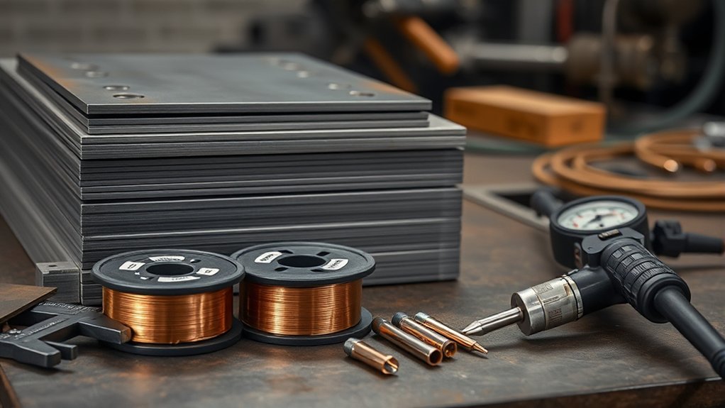
MIG wire size is the diameter of the continuously fed electrode. Common solid-steel sizes include .023″ or .024″ (about 0.6 mm), .030″ (0.8 mm), .035″ (0.9 mm), and .045″ (1.2 mm).
Diameter affects the wire’s useful current range, deposition rate, feeding setup, and puddle behavior. Smaller wire usually gives you easier control at low current. Larger wire can carry more current and deposit more filler metal when the welder has enough output.
This guide mainly covers gas-shielded solid wire for mild and carbon steel, such as ER70S-6. Stainless steel, aluminum, metal-cored wire, and self-shielded flux-core wire need different consumables, gases, polarity, feeding parts, and settings. Review the wire type and classification before using any chart.
A general Miller solid-wire guide lists .023″ for 30-130 amps, .030″ for 40-145 amps, .035″ for 50-180 amps, and .045″ for 75-250 amps. These are useful current windows, not guaranteed material-thickness limits.
Wire that is too large for the machine’s low-end output can make thin sheet difficult to control. Wire that is too small for the required current may need an excessive feed rate or may not provide the desired deposition rate. Neither condition proves that the weld will be weak, because joint preparation, weld size, fusion, pass count, and technique also control the result.
Use the machine chart and wire manufacturer’s guidance as your starting point. Then inspect the bead for toe fusion, profile, porosity, undercut, and other MIG welding problems.
MIG Wire Size Chart by Metal Thickness
The following chart gives practical starting ranges for clean mild steel with gas-shielded solid wire. The ranges overlap because two wire diameters may both work on the same thickness when the machine, joint, position, and settings support them.
Note: This is not a welding procedure specification. For structural, load-bearing, pressure-containing, suspension, roll-cage, or other safety-critical work, use the governing code and an approved procedure.
| Metal size | Approximate thickness | Common solid-wire starting sizes | Practical guidance |
|---|---|---|---|
| 24-20 gauge | .024″-.036″ 0.6-0.9 mm |
.023″ or .024″ | Best starting range for delicate panels. Use tight fit-up, low settings, and spaced tack welds. |
| 18-16 gauge | .048″-.060″ 1.2-1.5 mm |
.023″, .024″, or .030″ | .023″ or .024″ gives easier heat control. .030″ can work when the machine has a stable low range. |
| 14-11 gauge | .075″-.120″ 1.9-3.0 mm |
.030″ or .035″ | .030″ suits many compact welders. .035″ may improve deposition when the required current supports it. |
| 1/8″ plate | .125″ 3.2 mm |
.030″ or .035″ | Both are common. Choose by the machine chart, joint type, position, and required weld size. |
| 3/16″ plate | .188″ 4.8 mm |
.035″, or .030″ when approved by the machine chart | Machine output becomes more important. Some joints may need beveling or more than one pass. |
| 1/4″ plate | .250″ 6.4 mm |
.035″ or .045″ | Use a capable welder. Joint preparation, root access, pass count, and duty cycle may limit the procedure. |
| 5/16″ and thicker | .313″+ 7.9+ mm |
.035″, .045″, or an industrial procedure | Do not select wire from thickness alone. Verify available current, transfer mode, bevel, preheat requirements, and multipass procedure. |
The thickness of the thinner joint member often controls burn-through risk, while the required weld size controls how much filler you must deposit. A large fillet on thick material may need several passes even when the wire can run at the required current. Review proper fillet weld sizing instead of choosing wire diameter from plate thickness alone.
Choose .023, .030, .035, or .045 Wire
Products Worth Considering
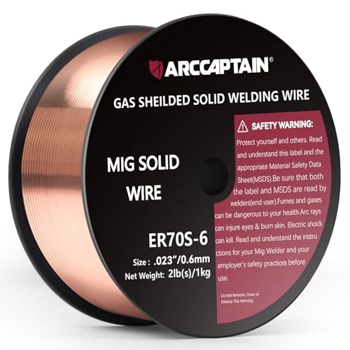
High-quality: ARCCAPTAIN's ER70S-6 mig welding wire .023" meets industry standards(Net Weight: 2lbs), ensuring consistent performance, superior strength. With its smooth feeding and stable welding parameters, you can achieve optimal penetration, high deposition rates, and exceptional overall welding performance.

ER70S-6 PERFORMANCE: This .023 MIG welding wire supports precise arc control and low spatter for single-pass and multi-pass welding.

ER70S-6 MIG WIRE: It's the most common wire of the copper-coated mild steel GMAW (MIG) wires for single or multiple pass welding.
Use .023 or .024 Wire for Thin Sheet Metal
Choose .023″ or .024″ solid wire when you weld automotive panels, ducting, appliance sheet, and other thin steel. These sizes operate well at lower current and make a small puddle easier to control.
The .023″ and .024″ labels usually describe the same nominal 0.6 mm wire category. Your welder or contact tip may mark it as .023″, .024″, .025″, or 0.6 mm, so check the machine manual before combining parts.
- Keep the joint clean and the gap as even as possible.
- Use short tack welds instead of one long bead when distortion is likely.
- Move between separated areas so heat does not collect in one spot.
- Test the lowest stable setting recommended by the machine chart.
Use .030 Wire for General Fabrication
.030″ wire offers a useful overlap between thin sheet and light plate. It is a common choice for compact 120-volt and 240-volt machines because it can run at moderate feed speeds across many light-fabrication jobs.
That versatility does not mean .030″ wire is automatically suitable for every joint through 3/8″ thick. A small machine may place a bead on thick plate without producing the root fusion or weld size required by the job. Match the wire to the welder’s current capacity and then tune the wire speed and voltage within the recommended range.
Pro Tip: Keep .023″ or .024″ wire for body panels and .030″ or .035″ wire for fabrication. Changing wire takes time, but forcing one diameter to cover every job often takes longer.
Use .035 or .045 Wire for Higher Output
.035″ wire supports a higher current and deposition range than .030″ wire. It is common on medium-output machines and can reduce the feed speed needed to reach a given amperage.
.045″ wire is normally used with larger feeders and power sources. It can deposit filler quickly, but it may be difficult or impossible to run correctly on a compact welder. Confirm that the gun liner, drive system, contact tip, duty cycle, and output range support .045″ wire.
- .035″ wire: useful for medium fabrication, larger fillets, and higher deposition than .030″
- .045″ wire: useful when an appropriate machine and procedure call for a higher current and deposition range
- Neither size: guarantees penetration without correct current, voltage, joint preparation, gas, stickout, and travel speed
Match Wire Size to Welding Position
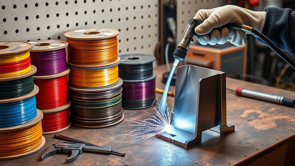
Welding position changes how gravity acts on the molten puddle. It may affect your transfer mode, wire-feed speed, voltage, travel direction, gun angle, and bead size. It does not create a universal rule that vertical or overhead welding always requires smaller wire.
Flat and horizontal joints usually let you control a larger, more fluid puddle, so higher-deposition procedures are easier to use. Vertical and overhead work normally needs a smaller, faster-freezing puddle. You may achieve that with lower settings, short-circuit transfer, pulse capability, a different travel technique, or a smaller wire when the procedure allows it.
- Flat: Follow the machine chart and required weld size. Higher-deposition settings may be practical.
- Horizontal: Watch the upper toe for undercut and the lower toe for excess buildup.
- Vertical: Use position-approved settings and control the puddle before increasing deposition.
- Overhead: Keep the puddle small and avoid settings that make it excessively fluid.
Do not copy settings directly from another welding process. Understanding process-specific amperage settings can help you compare procedures, but a stick-welding chart does not set MIG voltage or wire-feed speed.
How Joint Type Changes Wire Choice
Joint type changes the required weld size, root access, heat distribution, and amount of filler metal. Wire diameter can help you reach the needed deposition rate, but it should not be used to hide poor fit-up.
Butt Joint Gaps
A tight sheet-metal butt joint usually works best with .023″ or .024″ wire because the small puddle is easier to place. As plate thickness increases, a controlled root opening, bevel, backing method, or multipass sequence may be more important than moving to a larger wire.
- Tight thin-sheet joint: Use small wire and short tack welds to limit burn-through.
- Specified root opening: Follow the drawing or approved welding procedure.
- Accidental wide gap: Correct the fit-up when possible instead of relying on thicker wire.
- Thick groove weld: Verify bevel angle, root face, root opening, backing, and pass sequence.
A larger wire may add filler faster, but it can also increase the current and puddle size needed for stable operation. That can make an unsupported sheet-metal gap harder to bridge.
Lap Joint Fill
Lap joints concentrate heat along the exposed edge of the upper sheet. Match the setting to the thinner member and aim the arc so both pieces fuse without washing away the top edge.
.030″ or .035″ wire is a practical starting point for many light and medium lap joints. Use .023″ or .024″ when the upper sheet is thin and burn-through is the main concern. Do not choose wire from the combined thickness of both sheets alone.
Tee Joint Control
A tee joint normally requires a fillet weld sized for the load and the thinner connected member. A larger wire can increase deposition on a large fillet, but the machine must still deliver the required current while maintaining a stable arc.
- Small fillet on light steel: .030″ often provides good placement and control.
- Larger fillet: .035″ or .045″ may reduce the number of passes when the procedure supports it.
- Vertical or overhead fillet: Prioritize an approved transfer mode and controllable puddle.
- Uneven fit-up: Repair or restrain the joint before treating larger wire as the solution.
Note: Flux-cored electrodes are a separate consumable family. Some use an advanced core design for higher deposition or out-of-position control, but their gas, polarity, slag, and operating ranges cannot be copied from a solid-wire chart.
Avoid Burn-Through on Thin Sheet Metal
For thin steel, begin with .023″ or .024″ wire, a clean tight joint, and the lowest stable machine setting listed for that thickness. The smaller wire does not remove all burn-through risk, but it gives you a more manageable low-current range.
Warning: Thin sheet can burn through or warp in seconds. Wear full welding PPE, keep flammable material away, and let the panel cool between short welds. Do not look at the arc without a suitable welding helmet.
- Remove rust, paint, oil, plating, and other contamination from the weld zone using a safe method.
- Clamp the joint so the gap stays small and consistent.
- Use spaced tack welds and return after each area has cooled.
- Keep the gun angle and contact-tip-to-work distance consistent.
- Do not slow down excessively in an attempt to improve fusion.
- Use copper backing only when it is suitable and will not contaminate or interfere with the finished joint.
Most gas-shielded solid-steel MIG wire runs direct-current electrode positive, or DCEP. However, always verify the polarity on the wire label and machine diagram. Many self-shielded flux-core products use a different polarity.
Set shielding-gas flow according to the machine or wire manufacturer’s recommendation. Too little flow, a leak, or a draft can cause porosity. Excessive flow can create turbulence and draw air into the shielding envelope.
E71T-GS is a flux-cored electrode classification under AWS A5.20, not a solid MIG-wire standard. Products carrying that classification may be self-shielded, limited to specific passes, and assigned a product-specific polarity. Check the exact label before using any .035″ flux-core wire.
Fix Weak Penetration With the Complete Procedure
Changing to larger wire is not the first or only fix for weak penetration. Larger wire becomes useful when the required current or deposition rate is beyond the practical range of the smaller wire and the welder can support the change.
Check the complete procedure in this order:
- Clean the metal and work-clamp area. Rust, mill scale, paint, oil, and a poor return connection can reduce arc stability and fusion.
- Check joint preparation. Thick butt joints may need a bevel, root opening, backing, or access from both sides.
- Confirm polarity and gas. Use the wire manufacturer’s specified polarity and shielding gas.
- Check wire-feed speed. On a constant-voltage MIG machine, wire-feed speed strongly affects welding current.
- Set suitable voltage. Too little voltage may produce a convex bead with poor toe wetting. Too much can create undercut and poor control.
- Control stickout. Excessive contact-tip-to-work distance can reduce current and make penetration inconsistent.
- Correct travel speed. Travelling too fast can prevent fusion. Travelling too slowly can add excess heat without producing the desired root fusion.
- Verify machine capacity. A small welder may not have enough current or duty cycle for the required weld.
- Use the required number of passes. One oversized surface bead is not a substitute for a sound multipass sequence.
Pro Tip: Cut and inspect practice welds when penetration matters. Surface appearance can help you tune the arc, but it cannot prove complete root fusion by itself.
Wire size affects welding, while process gases have different roles in cutting equipment. Keep that separate from questions about whether a plasma cutter uses nitrogen.
Set Your Welder for the Right Wire
Start with the setting chart inside the welder, the owner’s manual, or a reliable manufacturer calculator. The Miller solid-wire parameter guide explains how material thickness, wire diameter, wire-feed speed, voltage, and travel speed work together.
Products Worth Considering

Package list: 30 pieces of 0.030 inch mig welder tips.

20Pcs Contact Tip .023'' Ø0.6mm

Package list : 20pk Contact tip 000068 Size:.035
Prepare the Wire-Feed System
- Turn the machine off and disconnect input power before changing internal feeding parts.
- Install a drive-roll groove intended for the wire diameter and type.
- Use a liner that covers the selected wire-size range.
- Install the correct contact tip. The wire size is normally marked on the tip.
- Set drive-roll pressure only high enough to feed the wire without slipping.
- Verify that the wire comes off the spool in the direction shown in the manual.
- Keep the gun cable as straight as practical while feeding new wire.
A Lincoln Electric manual advises matching the contact tip, liner, and drive rolls to the selected wire size. It also warns users to secure shielding-gas cylinders upright. Review the instructions for your own machine rather than assuming every feeder uses the same parts.
Set Polarity, Gas, Voltage, and Feed Speed
- Confirm the polarity shown on the wire label and welder diagram.
- Use the shielding gas approved for the filler wire and base metal.
- Select the material thickness and wire size on the machine chart.
- Set the listed voltage and wire-feed speed.
- Make a test weld on clean scrap with the same thickness and joint orientation.
- Change one control at a time in small steps.
Do not copy a solid-wire setting into a flux-core setup. Flux-core polarity, amperage, voltage, stickout, and gas requirements vary by classification and product. Use a process-specific flux-core amperage chart only after checking the wire data sheet.
MIG Setting Troubleshooting
| Symptom | Likely causes | What to check |
|---|---|---|
| Wire stubs into the work | Voltage too low for the feed rate, excessive feed speed, or poor work connection | Increase voltage slightly or reduce wire-feed speed within the chart range. Clean and tighten the work connection. |
| Wire burns back to the tip | Feed speed too low, voltage too high, feeding restriction, or damaged tip | Increase feed speed slightly, reduce voltage if needed, and inspect the tip, liner, drive roll, and cable path. |
| Tall convex bead with poor toe wetting | Low voltage, low current, fast travel, long stickout, or poor joint access | Use the recommended voltage and feed range, shorten excessive stickout, slow only if travel is clearly too fast, and check joint preparation. |
| Wide flat bead or undercut | Excessive voltage, current, travel speed, arc length, or poor gun angle | Reduce the excessive setting, correct gun angle, and keep the arc on both toes of the joint. |
| Burn-through | Too much heat, slow travel, wide gap, poor fit-up, or an oversized wire/setup | Lower the applicable settings, move slightly faster, tighten fit-up, use spaced tacks, or change to .023″/.024″ wire. |
| Porosity | No gas, low or excessive gas flow, draft, leak, clogged nozzle, or contamination | Check the cylinder, regulator, hose, fittings, nozzle, flow setting, wind protection, and surface cleanliness. |
Common MIG Wire Size Mistakes to Avoid
- Using .035″ or .045″ wire on thin sheet when the machine cannot run it smoothly at low current
- Assuming .030″ wire makes a compact welder suitable for every joint through 3/8″ plate
- Moving to larger wire before correcting voltage, feed speed, travel, stickout, joint preparation, or polarity
- Using larger wire to hide an accidental root gap or poor fit-up
- Forgetting to change the contact tip, liner, or drive-roll groove
- Using solid-wire polarity for a self-shielded flux-core product without checking the label
- Copying settings between carbon steel, stainless steel, and aluminum
- Ignoring duty cycle and continuing after the machine reaches its thermal limit
- Judging structural strength only from the appearance of the bead
Welding Safety Before You Start
Wire selection does not remove the normal hazards of arc welding. Read your welder manual, filler-metal information, safety data sheets, employer procedures, and applicable codes before starting.
Warning: Welding fumes, ultraviolet radiation, hot metal, sparks, electricity, and compressed gas can cause severe injury. Do not weld in a confined or enclosed space without the required ventilation, atmospheric controls, permit, rescue plan, and trained supervision.
- Wear a welding helmet with a suitable filter shade, safety glasses, flame-resistant clothing, welding gloves, and protective footwear.
- Use local exhaust or effective general ventilation to keep fumes away from your breathing zone.
- Remove coatings and residues that can create toxic fumes, using a method appropriate for the material.
- Do not use chlorinated cleaners near an active arc.
- Move combustible material away and keep suitable fire-control equipment nearby.
- Protect nearby people with welding screens and warning controls.
- Secure shielding-gas cylinders upright and protect valves from impact.
- Inspect cables, the gun, work clamp, regulator, hoses, and fittings before welding.
- Do not weld a container, tank, wheel, frame, pressure part, or safety-critical structure unless you are trained and the approved procedure covers the work.
The OSHA welding-fume fact sheet explains that outdoor work does not automatically provide enough ventilation. It recommends keeping exhaust collection close to the plume source and staying out of the fume path.
Frequently Asked Questions
What size MIG wire should you use for sheet metal?
Use .023″ or .024″ solid wire for most thin automotive and sheet-metal work. .030″ can work on heavier sheet when the welder has a stable low setting, but the smaller wire normally gives you easier heat control.
Should you use .030 or .035 MIG wire?
Use .030″ wire when you want a broad range for light and medium fabrication. Choose .035″ when the required current or deposition rate is higher and your welder, gun, liner, drive roll, contact tip, and procedure support it.
Can you weld thin metal with .035 wire?
You can weld some thin metal with .035″ wire when the machine can run it smoothly at a low setting. However, .023″ or .024″ wire is normally easier to control and gives you a wider margin against burn-through.
Does bigger MIG wire mean a stronger weld?
No. Larger wire can support more current and a higher deposition rate, but weld strength also depends on filler classification, weld size, joint preparation, fusion, settings, travel speed, pass sequence, defects, and base-metal properties.
Do you need to change the contact tip when wire size changes?
Yes. Match the contact tip to the wire size recommended by the gun or welder manufacturer. Also check the liner range and drive-roll groove, because all three parts affect feeding and current transfer.
What size MIG wire is best for 16-gauge steel?
For 16-gauge steel, .023″ or .024″ solid wire gives you the easiest heat control. .030″ is also common when the machine chart lists a suitable low setting and the joint fit-up is tight.
Can .030 MIG wire weld 1/4-inch steel?
It may be used in some 1/4-inch procedures, but wire diameter alone does not prove that the machine can make the required weld. Check available amperage, joint type, bevel, root access, pass count, duty cycle, and the welder manufacturer’s chart.
Are .023 and .024 MIG wire the same?
They commonly refer to the same nominal 0.6 mm wire category. Manufacturers may label the wire, contact tip, or feeder parts as .023″, .024″, .025″, or 0.6 mm. Confirm compatibility in the machine and gun documentation.
What MIG wire size should you use for 3/8-inch steel?
Do not choose from thickness alone. .035″ or .045″ may be suitable with a capable machine, but a 3/8-inch joint may need beveling, multiple passes, specific gas and transfer mode, preheat, or a qualified welding procedure.
Conclusion
The best MIG wire size depends on more than material thickness. Use .023″ or .024″ wire for easier control on thin sheet, .030″ for a broad light-fabrication range, and .035″ or .045″ when the required current and deposition rate justify the change.
Before welding the finished part, match the contact tip, liner, drive roll, polarity, gas, voltage, and wire-feed speed. Test the setup on clean scrap with the same thickness and joint position.
For thick, load-bearing, or safety-critical work, use an approved procedure rather than relying on a general wire-size chart. Correct joint preparation and verified fusion matter more than the diameter printed on the spool.
Sources
- American Welding Society: What Is GMAW? — GMAW definition, equipment variables, and shielding-gas overview
- Miller: MIG Welding Setting the Correct Parameters — general wire current ranges, wire-feed speed, voltage, travel speed, and bead diagnosis
- Miller Solid-Wire Welding Calculator — manufacturer starting settings for solid-wire GMAW
- OSHA: Controlling Hazardous Fume and Gases During Welding — ventilation, coating, fume, gas, and confined-space safety
- Lincoln Electric POWER MIG 200 Manual — contact-tip, liner, drive-roll, cylinder, gas, and feeder setup
- Hobart Brothers E71T-GS Certificate — E71T-GS classification and AWS A5.20 specification reference




