When I first picked up a no gas MIG welder, I was overwhelmed by the wire choices, polarity markings, machine controls, and safety warnings. I soon learned that “no gas MIG” is the common name for self-shielded flux-cored arc welding, or FCAW-S. It uses a continuously fed tubular wire that protects the weld without an external gas cylinder.
The process is beginner-friendly, but it is not automatic. Strong, repeatable welds still depend on using compatible wire, preparing the joint, setting the machine correctly, dragging the gun at the right angle, and inspecting the finished bead. This guide shows you how to set up, practice, troubleshoot, and use a no gas MIG welder more safely.
A compact wire-feed welder set up for beginner self-shielded flux-core practice.
Quick Answer
A no gas MIG welder is a self-shielded flux-core welder. Load compatible wire, use the polarity printed on its label, start with the machine’s settings chart, clean and clamp the steel, and drag the gun at a slight angle. Practice on matching scrap, remove the slag, inspect the bead, and never skip ventilation or fire protection.
Key Takeaways
- “No gas MIG” normally means self-shielded flux-cored arc welding, not true gas-shielded MIG.
- Polarity is wire-specific. Many hobby E71T-11 wires use DCEN, but you must check the spool or datasheet.
- Drag self-shielded flux-core wire at a slight angle and use the stick-out recommended by the wire manufacturer.
- Start with the machine chart instead of copying another welder’s voltage and wire-speed numbers.
- Use clean practice steel, remove slag between passes, and inspect every bead before attempting a real project.
- Do not use beginner practice welds for chassis, suspension, trailer hitches, lifting devices, pressure vessels, or other safety-critical structures.
At a Glance
| Time Required | About 30–60 minutes for first-time setup, plus at least 1–2 hours of scrap-metal practice |
| Difficulty | Beginner-friendly for basic steel practice; advanced for load-bearing or safety-critical work |
| Tools Needed | Flux-core-capable welder, compatible wire, helmet, safety glasses, gloves, flame-resistant clothing, pliers, wire brush, chipping hammer, clamps, grinder, and scrap steel |
| Cost | Varies by machine and PPE; wire, contact tips, abrasive discs, and practice steel are the main recurring costs |
What Is a No Gas MIG Welder and How Does It Work?
A no gas MIG welder uses self-shielded flux-cored wire instead of the solid wire and external shielding gas used for conventional MIG welding. The wire is a tubular consumable electrode filled with fluxing ingredients. When the arc melts the wire, those ingredients help protect the weld pool and form a slag layer over the cooling weld.
The machine feeds the wire continuously through the gun while you hold the trigger. The wire carries current, creates the arc, and supplies filler metal to the joint. After the bead cools, you must chip and brush away the slag before inspecting the weld or depositing another pass.
The more precise technical name is self-shielded flux-cored arc welding, or FCAW-S. The American Welding Society distinguishes it from gas-shielded FCAW, which uses both flux-cored wire and an external shielding gas. You can read its current overview in the AWS guide to flux-cored arc welding.
I first used a flux-core welder while repairing a rusty gate. The simple wire-fed setup gave me confidence, but I still had to grind the joint to sound metal. FCAW-S can tolerate light mill scale and minor surface contamination better than gas MIG, but it cannot reliably weld through oil, moisture, thick rust, paint, undercoating, or unknown plating.
Why Choose a No Gas MIG Welder?
- Simple gasless setup: You do not need a shielding-gas cylinder, regulator, or gas hose.
- Portability: The machine and wire are easier to move when there is no cylinder attached.
- Outdoor usefulness: FCAW-S tolerates outdoor air movement better than gas-shielded MIG, although you still need a dry, safe work area.
- Useful steel penetration: Many self-shielded wires work well for general steel fabrication and repair within the machine’s rated capacity.
- Lower setup complexity: Once the correct wire, drive roll, polarity, and contact tip are installed, there are fewer gas-related controls to manage.
Note: Self-shielded flux-core is more tolerant of outdoor conditions than gas MIG, but it is not weatherproof. Do not weld in rain, on wet steel, in standing water, or where strong wind prevents you from controlling the arc and fumes.
The Polarity Mistake Beginners Must Avoid
Many common hobby wires, including numerous E71T-11 products, operate on DC electrode negative, or DCEN. However, DCEN is not a universal rule for every flux-cored wire. Some industrial self-shielded wires use DCEP.
Before loading the spool, read the wire label, manufacturer datasheet, and machine chart. Set the gun lead and work lead to the polarity specified for that exact wire. The wrong polarity can create excessive spatter, an unstable arc, poor bead shape, and inadequate fusion.
Warning: Do not assume that every spool marked “flux core” uses the same polarity. Shut off and unplug the welder before opening the machine or changing internal lead connections.
Choosing the Best No Gas MIG Welder for Beginners
A beginner welder should be easy to set up, compatible with commonly available self-shielded wire, and powerful enough for the steel thickness you plan to practice on. Do not choose a machine only by its maximum amperage. Input power, duty cycle, controls, wire capacity, service support, and replacement consumables also matter.
Products Worth Considering
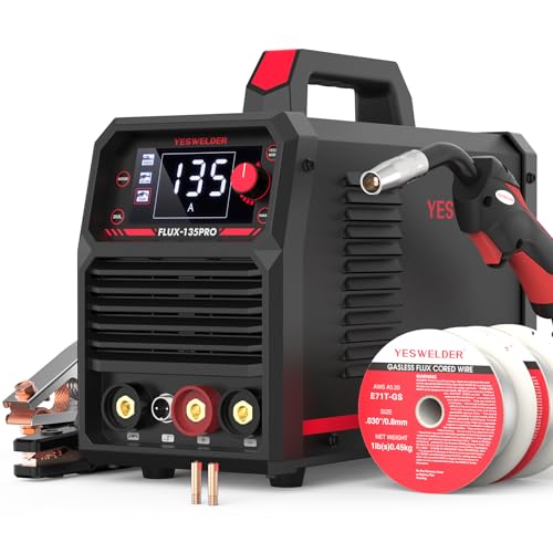
READY OUT OF THE BOX: Start welding immediately! It masterfully handles Gasless Flux Core MIG, Stick, and Lift TIG (Extra Lift TIG torch required). This budget-friendly 3-in-1 machine includes extra E71T-GS .030''&.035'' flux core wires, known for its smooth arc and high feedability. Say goodbye to heavy shielding gas cylinders—perfect for outdoor, windy, or all-position welding.

LARGE LED DIGITAL DISPLAY: The advanced digital display ensures crystal-clear visibilityeven in low-light environments, allowing welders to monitor parameters effortlessly. Its intuitive interface simplifies setup, it is easy to use with this welder machine.

WELD ANYWHERE: Plug in the Weld-Pak 90i FC wire feed welder anywhere 120V input power is available; It’s a versatile, user-friendly welding machine that welds up to 1/4"and can be used anywhere, from home workshops to construction sites
Key Features to Look For
- Correct input power: Confirm whether the welder requires 120V, 230/240V, or supports both. Check the required branch circuit and plug before buying.
- Polarity change capability: A machine that supports both solid-wire MIG and FCAW-S should provide accessible polarity connections or a tool-free polarity system.
- Useful output range: Low-end control matters for sheet metal, while higher output and adequate duty cycle matter for thicker joints.
- Adjustable voltage and wire speed: Independent controls make it easier to fine-tune the arc after using the chart as a starting point.
- Compatible drive rolls: The machine should support a knurled or V-knurled groove for soft tubular flux-cored wire.
- Supported wire diameters: Confirm that the gun, liner, contact tips, and drive roll support the wire you intend to use.
- Duty cycle: This rating tells you how long the machine can weld within a ten-minute period at a stated output before it needs to cool.
- Thermal protection: It protects the machine from overheating, but it does not increase the stated duty cycle.
- Portable construction: Compare the real machine weight, lead length, and carrying design rather than relying on the word “portable.”
- Parts and service support: Contact tips, nozzles, liners, drive rolls, guns, and service information should be easy to obtain.
Current Beginner-Friendly Models to Compare
The following are current manufacturer-listed examples as of July 20, 2026. They are comparison points rather than universal recommendations. Match the machine to your electrical supply, projects, training goals, and local support.
| Welder Model | Input | Output Range | Net Weight | Why Compare It |
|---|---|---|---|---|
| Hobart Handler 140EZ | 120V | 30–140A | 53 lb | Simple 120V wire-feed machine with flux-core capability and beginner-oriented controls |
| Lincoln Electric WELD-PAK 180i MP DV | 120/230V | 30–180A MIG/FCAW | 34.5 lb | Dual-voltage, multi-process design with tool-free polarity changes |
| Miller Multimatic 215 | 120/240V | Up to 230A, process-dependent | 38 lb | Portable multi-process platform for someone who expects to expand beyond FCAW-S |
I originally started with a Hobart Handler 140 because it ran from a normal 120V supply and gave me straightforward wire-feed controls. The newer Handler 140EZ fills a similar role. A dual-voltage machine such as the Lincoln WELD-PAK 180i MP DV or Miller Multimatic 215 gives you more room to grow, but only when your electrical supply supports it.
Pro Tip: Download the owner’s manual before buying. Check the required circuit, plug type, wire sizes, included drive rolls, duty cycle, polarity procedure, and rated material range before comparing extra features.
Understanding Flux-Cored Wire Types
The wire determines the required polarity, usable positions, strength classification, recommended stick-out, and whether multiple passes are allowed. Do not choose wire only by diameter or by the words “gasless flux core.”
Common Flux-Cored Wire Classifications
E71T-GS: This classification is commonly sold for general repair and sheet-metal work. It is usually intended for single-pass applications, and its exact operating requirements can vary by manufacturer. Read the product datasheet before using it.
E71T-11: This is a common self-shielded mild-steel classification used for general fabrication. Many E71T-11 products support all-position, single-pass, and multiple-pass welding, but diameter and manufacturer limits still apply. Hobart’s Fabshield 21B is one official example.
E70T-4: This is an industrial high-deposition classification rather than a default beginner wire. Products in this class may use large wire diameters, DCEP, long stick-out, and flat or horizontal positions. Use it only when your equipment, procedure, and training match the wire datasheet.
For my early workbench practice, I used 0.035-inch mild-steel wire on 1/8-inch coupons. The useful lesson was not that one diameter always produces the best bead. It was that the wire, machine chart, contact tip, drive roll, polarity, and steel thickness must all agree.
Choosing Wire Diameter
- 0.030-inch wire: A useful general-purpose size for many small 120V machines and lighter steel within the manufacturer’s range.
- 0.035-inch wire: Often chosen for thicker material or machines with more output capacity.
- 0.045-inch and larger wire: Intended for machines, guns, drive systems, and procedures that specifically support it.
Smaller wire can make low-output control easier, but it does not make every machine suitable for automotive sheet metal. Minimum stable output, joint fit-up, travel technique, tack sequencing, and heat management are equally important.
Match the Wire to the Base Metal
Most entry-level self-shielded machines are used with mild-steel wire on carbon steel. Stainless flux-cored products exist, but many require external shielding gas, specific polarity, and controls for chromium-containing fumes. Check the complete wire specification instead of assuming that a mild-steel setup can be used unchanged.
Practical consumer aluminum flux-core wire is not a normal FCAW-S option. Aluminum is generally welded with gas-shielded MIG and suitable wire-feeding equipment, such as a spool gun, or with an appropriate TIG process.
Store the Wire Correctly
Flux-cored wire can rust or absorb damaging contamination when stored in a damp area. Keep the spool dry, covered, and inside its original packaging when possible. Discard wire that is visibly rusty, kinked, contaminated, or feeding inconsistently.
I once blamed a wire jam on the machine before noticing that I had installed the wrong contact tip and overtightened the drive roll. Matching every feed component to the wire diameter prevents many of the problems beginners mistake for an electrical setting issue.
What You Need Before Setting Up the Welder
- A wire-feed welder approved for self-shielded flux-cored wire
- Compatible FCAW-S wire with a readable label or datasheet
- The correct contact tip and liner range
- A knurled or manufacturer-approved flux-core drive-roll groove
- Welding helmet with a suitable shade setting
- Safety glasses worn under the helmet
- Dry leather welding gloves
- Flame-resistant long sleeves and cuffless pants
- Leather footwear that covers the ankles
- Hearing protection when grinding or chipping slag
- Chipping hammer and dedicated wire brush
- MIG pliers or side cutters
- Angle grinder with suitable cleaning abrasives
- Metal clamps and a stable welding table
- Clean mild-steel practice coupons of known thickness
- Suitable fire extinguisher and a fire-safe work area
- Local fume extraction or other ventilation selected for the material and space
Warning: Never weld on a used drum, fuel tank, closed tube, cylinder, or other container unless it has been professionally cleaned, opened, vented, and declared safe for hot work. Residue and trapped pressure can cause an explosion.
Products Worth Considering

AUTO DARKENING FILTER - This welding helmet comes with high-end auto-darkening lens and 4 premium arc sensors which let you adapt to different working environments by adjusting the lens's shade and sensitivity while you are operating ARC/MIG/TIG Welding. DIN4 on light state, DIN5-9/9-13 on dark state.

Advanced Blue-Light Shield for Long Shifts: Say goodbye to burning eyes and "arc flash" after a long day in the shop. This upgraded welding hood features a precision blue-light blocking outer lens that filters out harmful radiation before it reaches your eyes. Whether you are doing quick weekend garage repairs or pulling a 10-hour shift, it guarantees exceptional eye comfort and long-term vision protection.

True Color Clear View: A 3.64" x 1.67" viewing area with 1/1/1/1 optical clarity delivers a true color view for improved visibility and reduced eye strain.
Setting Up Your No Gas MIG Welder Step by Step
Small setup errors can produce the same symptoms as poor technique. Work through the following sequence before changing several controls at once.
1. Read the Machine and Wire Instructions
Confirm the input circuit, supported wire size, drive-roll groove, contact tip, polarity, welding positions, and recommended parameter range. Keep the wire label until the spool is empty.
2. Turn Off and Unplug the Welder
Disconnect input power before opening the wire compartment, changing polarity leads, installing a drive roll, or feeding wire by hand. Keep the gun trigger protected from accidental activation.
3. Install the Correct Drive Roll
Self-shielded wire is softer than solid steel wire. Use the knurled or V-knurled groove recommended by the machine manufacturer. Match the groove to the wire diameter and confirm that the printed groove marking corresponds to the active groove.
4. Load the Spool
Install the spool in the direction shown in the manual. Set only enough hub tension to prevent the spool from coasting after the trigger is released. Excessive hub tension makes the feeder work harder.
5. Feed the Wire Without Crushing It
Guide the trimmed wire through the inlet guide and drive roll. Close the pressure arm and apply only enough drive-roll pressure to feed reliably. Too much pressure can flatten tubular wire and damage the liner.
6. Install the Matching Contact Tip
Use a contact tip marked for the wire diameter. Replace a tip that is enlarged, burned, blocked, or causing intermittent electrical contact. A flux-core nozzle can improve visibility and protect the diffuser, but it does not replace the contact tip.
7. Set the Required Polarity
Follow the polarity printed on the wire spool or datasheet. For many common DCEN wires, the gun lead connects to negative and the work lead connects to positive. Do not copy this arrangement unless it matches your exact wire.
8. Prepare the Joint
Remove oil, moisture, paint, undercoating, loose rust, plating, and heavy scale from the joint and nearby heat-affected area. Fit the pieces tightly and clamp them so they cannot move. Bevel thicker butt joints when the procedure requires access to the joint root.
9. Attach the Work Clamp
Attach the work clamp directly to clean bare metal on the workpiece or welding table. Place it close enough to provide a reliable circuit without interfering with the gun or clamps.
The work clamp is often called a ground clamp, but its main welding function is to complete the output circuit. It does not replace the equipment grounding conductor or protect you from shock caused by damaged leads, wet gloves, or unsafe wiring.
10. Start With the Machine Chart
Use the chart inside the wire compartment or in the owner’s manual. Select the row for your wire type, wire diameter, material thickness, and input voltage. Treat those values as a starting point rather than a guarantee.
11. Test on Matching Scrap
Use scrap with the same alloy, thickness, joint type, orientation, and preparation as the project. Run short beads, change one control at a time, clean the slag, and inspect the result before welding the actual joint.
When I prepared for a farm-gate repair, testing on matching tubing showed that my first setting was too hot for the joint gap. Correcting the fit-up and reducing the setting before touching the gate prevented burn-through.
Pro Tip: Keep a notebook with the machine, input voltage, wire brand and classification, diameter, polarity, material thickness, joint type, position, voltage setting, wire-speed setting, and test result. Do not save only the two dial numbers.
How to Tune Voltage and Wire Feed Speed
Voltage mainly affects arc length and bead profile, while wire feed speed strongly influences welding current on a constant-voltage wire feeder. The two controls interact, so make small changes and retest.
Signs the Wire Feed May Be Too Fast
- The wire repeatedly stubs into the work
- The gun pushes back against your hand
- The bead is tall, rope-like, or poorly tied into the toes
- Spatter increases while the arc sounds harsh
Signs the Wire Feed May Be Too Slow
- The wire burns back toward the contact tip
- The arc repeatedly goes out
- The bead is narrow and inconsistent
- The contact tip overheats or the wire fuses to it
Signs the Voltage May Be Too High
- The arc is long and harsh
- Spatter and undercut increase
- The bead becomes excessively flat or wide
- Thin material burns through quickly
Signs the Voltage May Be Too Low
- The arc feels erratic or repeatedly shorts
- The bead sits high with poor toe fusion
- Slag becomes difficult to control
- The weld shows lack of fusion after sectioning a practice coupon
Sound can help, but it is not a quality test. Some FCAW-S wires sound rougher than solid-wire MIG even when the settings are correct. Judge the arc together with bead shape, slag behavior, fusion, and the wire manufacturer’s parameter range.
Mastering No Gas MIG Welding Technique
Use a Drag Technique
For normal self-shielded flux-core welding, point the gun back toward the weld pool and move away from the completed bead. A simple memory aid is: if there is slag, drag.
Use a travel angle of about 5 to 15 degrees unless the wire instructions specify something different. Excessive angle can increase spatter, reduce penetration, and make the arc less stable. Miller provides additional position guidance in its flux-cored welding basics guide.
Use the Correct Work Angle
- Butt joint: Hold the gun near 90 degrees to the face of the joint so heat is shared between both pieces.
- T-joint: Start near a 45-degree work angle so the wire points into the root.
- Lap joint: Aim more heat toward the lower or thicker member while maintaining fusion at both toes.
- Horizontal joint: Adjust the work angle slightly upward to help support the weld pool against gravity.
Maintain the Correct Stick-Out
Stick-out is the unmelted wire extending from the contact tip to the arc. Many common FCAW-S procedures use more stick-out than solid-wire MIG. About 3/4 inch is a useful general starting point for common hobby wire, but the correct range may be longer or shorter.
Always use the wire datasheet as the final authority. Excessive stick-out can reduce current and cause an unstable arc or poor penetration. Stick-out that is too short can cause burnback and obstruct your view of the pool.
Control Travel Speed
Move fast enough to prevent an oversized, overheated bead but slowly enough to keep the arc at the front of the weld pool and fuse both sides of the joint. Travel that is too fast can produce a narrow bead, undercut, or lack of fusion. Travel that is too slow can create excessive buildup, heat input, distortion, or burn-through.
I once rushed a practice trailer coupon and produced a narrow bead that cracked during a bend test. The surface looked acceptable until I cut and bent the coupon. That experience taught me to inspect practice welds instead of judging strength from appearance alone.
Keep Weaving Small
Use a straight stringer bead for most beginner practice. A small side-to-side motion can help fill a wider joint, but a large weave can trap slag, overheat the joint, and hide poor fusion. Pause only enough to tie into each side.
Remove Slag Between Passes
Allow the bead to cool enough for safe cleaning. Chip the slag and brush the weld until you can see clean metal. Never deposit another pass over loose slag, spatter, or defects. Grind out cracks, visible porosity, trapped slag, or incomplete areas before continuing.
A smooth-looking bead is not proof of a strong weld. Joint preparation, root fusion, toe tie-in, internal defects, and the correct procedure matter more than appearance alone.
Beginner Practice Sequence
1. Run Beads on a Flat Plate
Mark straight lines on clean plate and run separate stringer beads. Focus on consistent stick-out, drag angle, travel speed, and bead width. Clean every bead before comparing it with the previous one.
2. Build a Pad of Beads
Place each new bead partly over the previous bead after removing all slag. This teaches consistent overlap and helps you recognize slag inclusions.
3. Practice Lap Joints
Clamp two coupons with a controlled overlap. Tack both ends, then weld while directing enough heat into the lower plate. Cut and bend practice joints to examine fusion.
4. Practice T-Joints
Fit the pieces tightly at 90 degrees. Tack both ends and practice equal leg size with the wire aimed into the joint root.
5. Practice Butt Joints
Start with thicker coupons that are easier to control. Progress to thinner steel only after you can maintain consistent fit-up, tack spacing, and penetration without leaving holes.
Using a No Gas MIG Welder on Thin Sheet Metal
Thin sheet is one of the hardest jobs for self-shielded flux-core because the process produces concentrated heat, spatter, and slag. Lower settings help, but heat control depends just as much on joint fit-up and welding sequence.
How to Reduce Burn-Through and Distortion
- Use the smallest compatible wire recommended by the machine manufacturer.
- Remove rust and coatings without grinding the sheet unnecessarily thin.
- Keep gaps small and consistent.
- Use tight clamps to keep the joint aligned.
- Place short tacks instead of running one long continuous bead.
- Move between distant areas so one section can cool.
- Allow cooling time rather than trying to fill a growing hole with more wire.
- Use a clean copper backing bar where access and the repair design allow it.
- Practice on the same gauge and joint before touching the actual panel.
For a body-panel patch, I use spaced tacks and gradually fill the gaps after the metal cools. Trying to run a continuous bead on thin automotive sheet can warp the panel or create burn-through before you have time to correct the arc.
Note: Gas-shielded short-circuit MIG often gives better low-end control, less slag, and less cleanup on very thin automotive sheet. FCAW-S is useful, but it is not automatically the best process for every thin-metal repair.
How to Inspect a Practice Weld
Clean the slag and examine the entire bead under good light. A useful beginner inspection includes the following checks:
- Consistent width: Large changes often indicate inconsistent travel or stick-out.
- Toe tie-in: The bead should blend into both pieces without a rolled edge or visible gap.
- No cracks: Any visible crack is a reject and must be removed.
- No visible porosity: Pinholes suggest contamination, moisture, poor technique, or unsuitable parameters.
- No severe undercut: A groove beside the bead reduces the effective section.
- No trapped slag: Dark lines or pockets can indicate inadequate cleaning or poor bead placement.
- Appropriate reinforcement: A very tall rope-like bead may have poor fusion even when it looks neat.
- Controlled distortion: Excessive bending or warping points to poor heat sequencing.
For practice pieces, cut across the joint, grind and polish the cross-section, or perform an appropriate bend or break test in a controlled area. Destructive practice testing can expose incomplete fusion that is invisible from the surface.
Safety Considerations for No Gas MIG Welding
FCAW-S produces ultraviolet radiation, hot metal, sparks, slag, electrical hazards, noise, and welding fumes. OSHA identifies welding-related risks that include fume exposure, burns, eye injury, electrical shock, and fire. Review the agency’s welding hazards and solutions before setting up a work area.
Essential Safety Gear
- Welding helmet: Use a helmet approved for arc welding and select a shade suitable for the process and welding current.
- Safety glasses: Wear safety glasses with side protection under the helmet, especially while chipping slag.
- Leather gloves: Keep the gloves dry and replace them when they are torn or contaminated.
- Flame-resistant clothing: Cover your arms, torso, legs, ankles, and neck. Avoid synthetic clothing that can melt.
- Leather footwear: Use boots that prevent hot slag from entering around the ankle.
- Hearing protection: Wear it when grinding, chipping, or working in a noisy shop.
- Respiratory protection: Use only a respirator selected for the hazard, properly fitted, and used within an appropriate respiratory-protection program. A respirator is not a substitute for source control.
Control Welding Fumes
Keep your head out of the plume and use local exhaust positioned to capture fumes close to the arc without blocking your view or creating another hazard. A general shop fan that merely moves fumes past your face is not the same as local extraction.
Identify the base metal, filler wire, coatings, cleaners, and nearby contamination before welding. Galvanized coatings, stainless steel, lead paint, cadmium plating, and other materials can require specific ventilation or respiratory controls. OSHA’s welding, cutting, and brazing requirements describe ventilation and material-specific precautions.
I once welded in a tight shed with poor airflow and developed a headache. I no longer treat an open door or small fan as proof that the breathing zone is controlled. I position extraction near the source and stop if fumes collect around my helmet.
Prevent Fire
- Move combustible material away from the welding area.
- Check both sides of walls, floors, panels, and enclosed spaces for hidden combustibles.
- Protect openings that could allow sparks to reach another room or floor.
- Keep suitable extinguishing equipment ready for immediate use.
- Assign a trained fire watch when the location or combustible hazards require one.
- Continue a required fire watch for at least 30 minutes after welding ends.
- Mark or guard hot metal so another person does not touch it.
Reduce Electrical Risk
- Keep gloves, clothing, leads, and the floor dry.
- Do not wrap welding leads around your body.
- Inspect the gun, work lead, plug, insulation, and connectors before use.
- Do not use damaged or undersized extension cords.
- Do not touch the wire electrode and workpiece with bare skin while the output is energized.
- Disconnect input power before servicing the feeder or changing polarity.
- Follow the machine manual for grounding, generator use, and branch-circuit requirements.
Protect Other People
Use noncombustible welding screens to protect nearby people from arc radiation and sparks. Screens must not block necessary ventilation. Keep children, pets, and unprotected observers out of the work area.
Warning: Do not weld in a confined space without a formal hazard assessment, ventilation plan, attendant, and rescue procedure. Do not use oxygen as ventilation.
Pros and Cons of No Gas MIG Welding
Pros
- No external shielding-gas system: Fewer components are needed for basic FCAW-S operation.
- Portable setup: You do not need to transport a gas cylinder for self-shielded work.
- Outdoor capability: It is more tolerant of outdoor air movement than gas MIG.
- Useful penetration: Suitable wire and settings can perform well on general steel fabrication.
- Continuous wire feed: It avoids repeated electrode changes associated with stick welding.
Cons
- More spatter and smoke: Cleanup and fume control require extra attention.
- Slag removal: Every pass must be cleaned before inspection or another pass.
- Harder thin-sheet control: Burn-through and distortion can be difficult to manage.
- Lower visibility: Smoke, slag, and a longer stick-out can make the pool harder to see.
- Limited material flexibility: Common entry-level FCAW-S equipment is mainly used on carbon steel.
- Wire-specific setup: Polarity, position, stick-out, and pass limits vary among products.
Real-World Applications for No Gas MIG Welding
- Practice and training: Run beads and build test joints on clean mild-steel coupons.
- Noncritical shop projects: Build carts, stands, brackets, tables, and simple steel furniture within your skill level.
- Farm and property maintenance: Repair noncritical gates, guards, and mild-steel fixtures after identifying the material and load.
- Outdoor fabrication: Work where a gas-shielded process would be difficult to protect from light air movement.
- Art and hobby projects: Build sculptures, planters, fire-pit components, and decorative frames using suitable steel.
- Equipment repair: Make noncritical repairs only when the base metal, loading, procedure, and inspection requirements are understood.
I have used flux-core wire for workbench frames, gate sections, and a backyard fire-pit project. I treat automotive body panels as a more demanding thin-sheet job, not an easy first project.
Warning: Chassis, suspension, steering, trailer hitches, roll cages, lifting equipment, pressure vessels, structural beams, and other safety-critical welds require qualified procedures, suitable materials, trained personnel, and appropriate inspection. Do not rely on a beginner practice bead for these applications.
Troubleshooting Common No Gas MIG Welding Problems
Excessive Spatter
- Possible causes: Wrong polarity, excessive voltage, unsuitable wire speed, incorrect stick-out, excessive gun angle, contamination, or unstable work-clamp contact.
- Fix: Verify the wire label, return to the machine chart, clean the joint and clamp area, restore the recommended stick-out, and change one setting at a time.
Poor Penetration or Lack of Fusion
- Possible causes: Output too low, travel too fast, stick-out too long, incorrect work angle, poor fit-up, heavy scale, or an unbeveled thick butt joint.
- Fix: Prepare the joint correctly, shorten the stick-out to the specified range, direct the wire into the root, reduce travel speed, or increase the setting within the wire and machine limits.
Porosity
- Possible causes: Oil, paint, moisture, rust, damp wire, excessive wind, an incorrect gun angle, or an excessively long arc.
- Fix: Grind to clean dry metal, replace contaminated wire, improve shelter and extraction, and restore the recommended angle and stick-out.
Burn-Through
- Possible causes: Excessive heat, travel too slow, a large joint gap, repeated welding in one area, or metal that was ground too thin.
- Fix: Reduce the setting, use short separated tacks, improve fit-up, allow cooling time, and use clean backing where appropriate.
Wire Stubbing Into the Work
- Possible causes: Wire feed too high for the voltage, travel too slow, poor electrical contact, or an obstructed liner.
- Fix: Return to the chart, check the clamp and connections, inspect the liner and tip, and reduce wire speed in small steps if required.
Burnback at the Contact Tip
- Possible causes: Wire feed too slow, stick-out too short, restricted feeding, or an incorrect contact tip.
- Fix: Replace the damaged tip, inspect the feed path, restore the correct stick-out, and balance wire speed with voltage.
Birdnesting or Wire Jams
- Possible causes: Excessive drive-roll pressure, a blocked liner, incorrect groove, wrong contact tip, kinked gun cable, spool overrun, or rusty wire.
- Fix: Cut out the tangled wire with the machine unplugged, inspect the liner and tip, straighten the gun cable, set proper hub tension, and reduce drive pressure.
I once dealt with repeated wire jams because I had overtightened the drive roll. Loosening the tension helped, but the complete fix was aligning the groove, installing the correct tip, and keeping the gun cable straighter.
Slag Inclusions
- Possible causes: Pushing the gun, failing to clean between passes, excessive weaving, poor work angle, or depositing metal over an unfilled joint corner.
- Fix: Drag the gun, remove all slag, use smaller beads, aim into the root, and grind out the defect before rewelding.
Undercut
- Possible causes: Excessive voltage, travel too fast, excessive gun angle, or failure to pause at the weld toe.
- Fix: Reduce the setting within the approved range, correct the angle, slow slightly, and use a controlled stringer bead.
Worm Tracks
- Possible causes: Gas from the flux becoming trapped as the slag freezes, excessive voltage, contaminated wire, or unsuitable parameters.
- Fix: Use dry wire, clean the joint, confirm the manufacturer’s stick-out and voltage range, and retest on scrap.
Conclusion: Why You’re Ready to Practice With a No Gas MIG Welder
A no gas MIG welder gives you a portable way to learn wire-feed welding without managing a shielding-gas cylinder. The best results begin with compatible FCAW-S wire, the wire-specific polarity, the correct drive components, clean steel, secure fit-up, and settings taken from the machine chart.
Drag the gun at a slight angle, maintain the recommended stick-out, remove slag between passes, and inspect every practice joint. Start with flat coupons and noncritical projects. Build skill through repeatable tests rather than assuming that an attractive bead is structurally sound.
Most importantly, treat ventilation, fire prevention, electrical safety, and project limits as part of the welding process. They are not optional steps added after the machine is set up.
Frequently Asked Questions
What is the best no gas MIG welder for a beginner?
The best machine is one that matches your electrical supply, material range, and training goals. Look for adjustable voltage and wire speed, accessible polarity changes, a flux-core drive-roll groove, thermal protection, clear setup charts, and readily available consumables. Current examples include the Hobart Handler 140EZ, Lincoln WELD-PAK 180i MP DV, and Miller Multimatic 215.
Can I use a no gas MIG welder on thin metal?
Yes, when the machine and wire are rated for the thickness. Use compatible small-diameter wire, tight fit-up, short spaced tacks, cooling time, and matching scrap for setup. Very thin automotive sheet is often easier to control with gas-shielded short-circuit MIG.
Should I push or pull a no gas MIG welder?
Pull or drag the gun for normal self-shielded flux-cored welding. Point the gun back toward the weld pool and use a slight travel angle, commonly about 5 to 15 degrees. Follow the wire manufacturer when it specifies a different technique.
What polarity does gasless flux-core wire use?
Many common E71T-11 hobby wires use DCEN, with the gun negative and work lead positive. However, some self-shielded wire uses DCEP. Use the polarity printed on the spool, datasheet, or manufacturer’s setup chart rather than relying on a universal rule.
How much stick-out should I use with flux-core wire?
Use the range specified by the wire manufacturer. Approximately 3/4 inch is a common starting point for many hobby FCAW-S setups, but some wires require a longer or shorter distance. Stick-out that is too long can reduce current, while stick-out that is too short can cause burnback.
How do I reduce spatter when using a no gas MIG welder?
Verify polarity, clean the steel and work-clamp area, use the recommended stick-out, keep the drag angle small, and return to the machine’s settings chart. Adjust only one control at a time and test each change on matching scrap.
Is no gas MIG welding safe for indoor use?
Indoor welding requires ventilation selected for the room, material, coating, wire, and amount of welding. Use local extraction where possible and keep your head out of the plume. Stainless steel, galvanized steel, lead paint, cadmium coatings, and confined spaces require additional controls. A household fan alone does not prove that fume exposure is safe.
Can I weld aluminum with a no gas MIG welder?
Not with ordinary consumer self-shielded flux-core wire. Practical aluminum FCAW-S wire is not normally available for this type of machine. Aluminum is generally welded with gas-shielded MIG using suitable wire-feeding equipment, such as a spool gun, or with an appropriate TIG process.
Can I weld stainless steel with a no gas MIG welder?
Only when the machine, wire, polarity, shielding method, and procedure are approved for that stainless grade. Many stainless flux-cored wires use external shielding gas. Stainless welding also creates chromium-containing fumes, so suitable extraction and exposure controls are essential.
Sources
- OSHA 29 CFR 1910.252: Welding, Cutting, and Brazing — fire prevention, PPE, containers, ventilation, fumes, and electrical precautions
- OSHA Welding, Cutting, and Brazing: Hazards and Solutions — overview of welding health and safety hazards
- Miller: Flux-Cored Welding Basics for Mild Steel — equipment setup, wire selection, stick-out, drag technique, and work angles
- American Welding Society: Flux Cored Arc Welding — FCAW-S terminology, process comparison, aluminum limitations, and troubleshooting
- Hobart Brothers Fabshield 21B — official E71T-11 application and pass information
- Lincoln Electric WELD-PAK 180i MP DV — current machine specifications and polarity-change features