Black smut around an aluminum MIG weld is frustrating, but it does not automatically mean the weld is weak. The dark deposit is usually aluminum or magnesium oxide that formed when vapor from the arc condensed on cooler metal beside the weld. Heavy smut can also point to poor shielding, contamination, an excessive gun angle, excessive contact-tip-to-work distance, or the wrong filler for the job.
You will get the cleanest result by working through the problem in order: confirm the aluminum and filler alloy, remove oil before brushing away oxide, verify the shielding-gas system, set up the wire feeder correctly, use a controlled push angle, and follow the starting parameters supplied by the welder or filler-wire manufacturer. Appearance matters, but it should never replace proper weld inspection.
Quick Answer
To reduce smut when MIG welding aluminum, degrease first, remove oxide with a dedicated stainless brush, use clean 100% argon at the manufacturer’s recommended flow, check for leaks and drafts, keep a 10–15-degree push angle, shorten excessive stickout, and choose filler wire that matches the base alloy and service requirements.
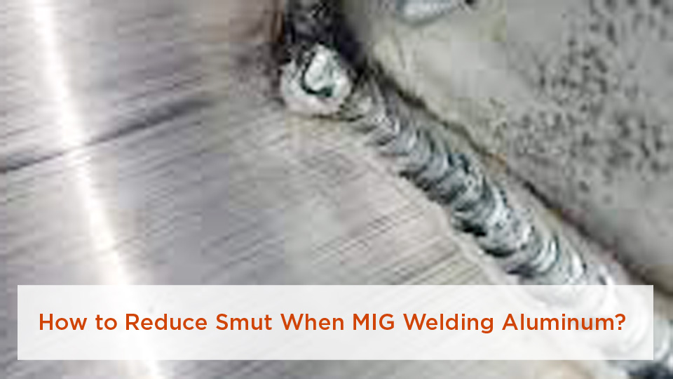
Image credit: Reddit, as supplied with the original article.
Key Takeaways
- Some black smut is normal with magnesium-bearing filler such as 5356, especially along the weld toes.
- Heavy, uneven, or bead-covering smut calls for checks of gas purity, flow, leaks, drafts, nozzle condition, gun angle, stickout, and surface cleanliness.
- Choose filler by base-alloy compatibility and service requirements, not by appearance alone.
- Use a push technique and a smooth, stable spray or pulsed-spray arc instead of dragging the gun.
- Clean the deposit before inspecting the weld for porosity, cracks, incomplete fusion, undercut, or cold lap.
At a Glance
| Time Required | About 15–30 minutes for cleaning, setup checks, and test beads, plus welding and cleanup time |
| Difficulty | Intermediate; beginners should practice on matching scrap before welding the part |
| Tools Needed | Aluminum-capable MIG welder, spool or push-pull gun, pure argon, flowmeter, dedicated stainless brush, lint-free cloth, approved degreaser, aluminum filler wire, PPE, and suitable ventilation |
| Cost | Usually limited to gas, wire, cleaning materials, and replacement gun consumables when the welding equipment is already available |
Warning: Welding produces intense UV radiation, hot metal, sparks, gases, and fine fumes. Use suitable eye, face, hand, skin, hearing, and respiratory protection based on the hazard assessment. Provide effective ventilation or local fume extraction, keep combustibles away, and never weld in a confined space without the required controls and authorization.
What Causes Black Smut in Aluminum MIG Welding?
Black smut is normally a loose surface deposit made from aluminum and magnesium oxides. As the filler wire crosses the arc, a small amount of metal can vaporize. That vapor travels beyond the best-protected part of the weld zone, reacts with oxygen, and condenses on the cooler base metal.
Magnesium-bearing filler wires usually produce more visible smut. ER5356 contains magnesium and commonly leaves a dark line at the weld toes. ER4043 contains silicon and normally creates a cleaner-looking bead with less smut. That difference is real, but it does not make 4043 suitable for every aluminum alloy.
Poor shielding can make the deposit heavier. Common causes include low gas flow, excessive gas flow that creates turbulence, an empty or incorrect cylinder, leaking connections, a damaged O-ring, a blocked diffuser, a dirty nozzle, a long contact-tip-to-work distance, strong drafts, or a steep gun angle that pulls air into the shielding envelope.
Oil, paint, moisture, hydrated oxide, shop dust, grinding residue, and a contaminated stainless brush can also cause discoloration, porosity, or an unstable arc. Erratic feeding adds another problem because the arc length and heat input change as the soft aluminum wire slips, shaves, birdnests, or burns back.
Smut is a troubleshooting clue, not a stand-alone weld inspection. Clean the surface first, then judge fusion, profile, porosity, cracks, undercut, and other acceptance requirements.
When Is Aluminum Weld Smut Normal?
Usually cosmetic
A narrow black or gray deposit beside the toes of a smooth ER5356 weld can be normal. If it wipes or brushes away easily and the cleaned weld has the required profile, fusion, and soundness, the deposit may be mainly cosmetic.
Possible warning signs
Stop and investigate when the deposit is unusually heavy, covers the face of the bead, appears only on one side, is paired with popping or an unstable arc, or returns after you correct the gun angle. Also inspect closely when you see pinholes, excessive reinforcement, undercut, lack of tie-in, cracks, crater defects, or a dull and irregular bead.
For structural work, pressure-containing components, vehicle repairs, lifting equipment, marine structures, or any safety-critical part, use the approved welding procedure and inspection requirements. The AWS D1.2 structural aluminum code applies to qualifying structural applications, but it does not cover every aluminum product or pressure system.
Prepare the Aluminum Before Welding
Preparation is the easiest place to prevent avoidable smut and porosity. Use the following order so you do not brush oil and grease deeper into the surface.
1. Identify the base alloy
Confirm the alloy whenever possible before choosing filler or a welding procedure. Aluminum that looks identical can require a different filler or may not be considered readily weldable by the selected process. Unknown scrap is a poor choice for a structural or safety-critical repair.
2. Remove paint, adhesive, heavy soil, and mechanical damage
Strip coatings far enough from the joint to prevent contamination and fumes. Use a method approved for the material and application. Avoid aggressive grinding that overheats the surface or smears contamination into the aluminum.
3. Degrease before brushing
Wipe the joint with a clean, lint-free cloth and a cleaner approved for aluminum. Acetone is commonly used, but it is highly flammable. Perform solvent cleaning away from the welding area, close the container, remove contaminated rags, and allow the surface to dry completely before striking an arc.
Warning: Never use chlorinated brake cleaner or another chlorine-containing solvent to prepare metal for arc welding. Heat and UV radiation from the arc can create highly toxic decomposition products. Read the cleaner’s safety data sheet before use.
4. Remove the oxide layer
After degreasing, brush the joint with a clean stainless-steel brush reserved only for aluminum. Brush in one direction with enough pressure to break the oxide without gouging or burnishing the surface. A low-speed dedicated power brush can be used when the manufacturer permits it, but heavy pressure can smear material and trap contamination.
Clean immediately before welding. Aluminum begins forming a new oxide film as soon as clean metal is exposed to air.
5. Control moisture and condensation
Do not weld aluminum while condensation is present. If the plate or filler wire came from cold storage, allow it to reach shop temperature in a clean, dry area. Keeping packaged filler wire dry and avoiding repeated movement through the dew point helps reduce moisture-related porosity.
A blanket preheat of 100–150°F is not automatically required. Preheat only when the equipment manufacturer, filler supplier, engineering procedure, or qualified WPS calls for it. Measure the temperature and remain within the limits for the alloy and procedure.
6. Check fit-up and joint preparation
Tight, consistent fit-up helps keep air and contamination out of the root. Remove burrs and provide the root opening, bevel, groove angle, and land required by the drawing or WPS. A 60-degree included groove may be suitable for some thicker butt joints, but it is not a universal rule for every thickness or process.
Pro Tip: Prepare a matching scrap coupon with the same alloy, thickness, joint, filler, position, and cleaning method. A test bead exposes gas, feeding, and parameter problems before they damage the finished part.
Choose the Right Filler Wire
Filler composition affects smut, but appearance should not be the first selection criterion. Start with the known base alloys and use the filler manufacturer’s compatibility chart. Then consider crack sensitivity, strength, ductility, corrosion resistance, elevated service temperature, anodizing color, toughness, and any planned post-weld heat treatment.
The ESAB comparison of 4043 and 5356 explains why both fillers can work on some common alloys while having different weldability, strength, ductility, feedability, and appearance characteristics.
| Filler Wire | Typical Advantages | Important Limitations | Common Considerations | Relative Smut |
|---|---|---|---|---|
| ER4043 | Fluid puddle, good wetting, smooth appearance, lower crack sensitivity in many common applications | Lower ductility and shear strength than 5356; may produce a different color after anodizing; not compatible with every high-magnesium base-alloy combination | Many 6xxx-series and general fabrication applications when approved by the selection chart | Low |
| ER5356 | Higher column strength for feeding, higher shear strength, good color match after anodizing in many applications | Creates more magnesium-oxide smut and is not the correct filler for every alloy or service condition | Many compatible 5xxx- and 6xxx-series combinations, marine work, trailers, and structural fabrication when specified | Medium to high |
| ER5556 | Higher deposited-metal strength than 5356 in suitable applications | Not a general substitute for 4043 or 5356; alloy compatibility and service requirements must be verified | Selected high-strength 5xxx-series applications under an approved procedure | Medium to high |
| ER4943 | Similar handling and weldability to 4043 with higher as-welded strength in appropriate joints | Availability and approval vary; must be checked against the base-alloy selection chart and procedure | A possible approved alternative to 4043 in selected 6xxx-series applications | Low to medium |
Note: A cleaner bead is not a valid reason to substitute 4043 for 5356 when the drawing, filler-selection chart, engineering calculation, corrosion requirement, or qualified WPS requires another filler.
Use the Correct Shielding Gas and Flow
Pure argon is the normal shielding gas for conventional MIG welding of aluminum. A flow near 20–30 cubic feet per hour is a common starting range on many systems, but nozzle size, gun design, joint access, position, and environmental conditions can change the requirement. Follow the machine and gun manufacturer’s recommendation.
Argon-helium mixtures can add heat and penetration on thick aluminum. They also change arc behavior, required flow, cost, and parameters. Do not substitute a helium blend without adjusting the procedure.
Products Worth Considering

Compatible with CGA-580 tanks: Easily attach this Gas Pressure Regulator/Flowmeter to your Argon, Helium, and CO2 tanks with its CGA-580 inlet connector

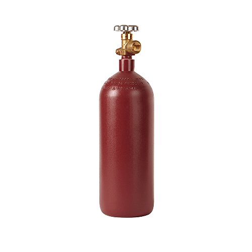
20 CU FT ARGON CYLINDER - Compact steel argon tank perfect for TIG welding, MIG welding, and hobby/small shop fabrication. 2015 PSI service pressure. Ultra-portable with 5.25" diameter x 18" height, 13.67 lb tare weight. Ideal for mobile welders, small shops, automotive repair, and DIY metalworking projects
Check the entire gas path
- Confirm that the cylinder contains the specified gas.
- Open the cylinder and check the regulator and flowmeter while gas is flowing.
- Inspect the hose, fittings, gun connection, O-rings, diffuser, and nozzle for leaks or damage.
- Clean the nozzle and diffuser so gas can exit evenly.
- Keep the nozzle close enough to protect the weld without causing burnback.
- Block fans, open doors, or outdoor wind that can strip away shielding.
- Do not solve every shielding problem by increasing flow. Excessive flow can create turbulence and draw surrounding air into the gas stream.
A MIG gun uses a gas diffuser and nozzle, not the TIG gas lens sometimes mentioned in general welding advice. A clean, correctly sized nozzle and an undamaged diffuser provide the most useful shielding improvement.
Set Up the Wire Feeder and Gun
Soft aluminum wire can shave, buckle, or birdnest if it is forced through a steel setup. A spool gun keeps the wire path short. A push-pull gun uses a motor in the gun to pull while the feeder assists from the power source. Either can provide reliable feeding when properly configured.
For a conventional feeder setup, use the aluminum components specified by the manufacturer:
- U-groove drive rolls that support rather than crush the wire
- Nonmetallic inlet and outlet guides
- An aluminum-compatible liner
- A contact tip intended for aluminum and matched to the wire diameter
- The lightest drive-roll pressure that feeds without slipping
- A straight gun cable with no unnecessary loops or sharp bends
ER5356 is stiffer and usually feeds more easily through a longer system than the softer ER4043. Wire diameter also matters. A 0.035-inch wire may work well on some light-production or spool-gun systems, while 3/64-inch wire is common for broader aluminum MIG use. Match every feed component to the actual wire size.
Choose Machine Settings That Produce Stable Transfer
There is no universal aluminum setting. Start with the chart inside the welder, the digital setup menu, the filler-wire data sheet, or a qualified WPS. Match the chart to the base-metal thickness, wire diameter, filler alloy, gas, joint, position, and transfer mode.
On some conventional systems welding approximately 1/8-inch aluminum with 0.035-inch wire, a starting range may fall near 18–22 volts and 300–400 inches per minute. Other machines require a meaningfully different voltage or wire-feed speed, especially with 3/64-inch wire, a helium blend, pulsed output, or a different joint. Treat those numbers as machine-specific examples, not a recipe.
In constant-voltage MIG welding, wire-feed speed strongly influences current. A display may show approximately 100–150 amps in some thin-material setups, but you should not set amperage independently unless the machine’s control system is designed that way.
Use spray or pulsed-spray transfer
Conventional aluminum MIG commonly uses spray transfer. The arc should sound smooth and steady, not like the repeated crackling often described as “frying bacon” in short-circuit steel MIG. Frequent popping, stub-out, or burnback means the arc, feeding, stickout, or parameters need attention.
Pulsed-spray MIG alternates between peak and background current. When the machine supports it, pulsed output can reduce average heat input, improve puddle control, and lower the risk of burn-through on thinner material. It still requires the correct program, wire, gas, and technique.
Use the correct polarity
Aluminum GMAW normally uses direct-current electrode positive, also called DCEP or DC+. Confirm the polarity in the equipment manual. Do not reverse polarity as a general attempt to reduce smut.
Control stickout and contact-tip-to-work distance
Keep the contact-tip-to-work distance within the gun or procedure recommendation. A value around 3/8–1/2 inch may work for some conventional spool-gun setups, while other spray or pulsed applications require a longer distance. Excessive distance can reduce shielding and arc stability. Too little distance can overheat the contact tip and cause burnback.
Pro Tip: Change one variable at a time on the test coupon. Record the wire, gas, flow, voltage or program, wire-feed speed, trim, CTWD, and travel speed after you find a clean and repeatable setup.
Use a Push Technique and Correct Gun Angles
Push the gun so the wire and nozzle point in the direction of travel. A 10–15-degree push travel angle is a useful general target for many aluminum MIG joints. Dragging the gun places less shielding ahead of the puddle and often produces a dirtier, more porous weld.
Separate travel angle from work angle
The travel angle is the forward tilt in the direction of movement. The work angle aims the gun across the joint. On a flat fillet weld between equal-thickness pieces, the work angle is often close to the joint bisector. When one member is thicker, the procedure may direct more heat toward that member.
A travel angle that is much steeper than the recommended range can stretch or disturb the gas envelope. If smut appears mainly on one side, correct the work angle, nozzle access, CTWD, or gas coverage rather than merely trying to move the soot.
Maintain a steady travel speed
Aluminum carries heat away quickly at the start, then becomes easier to overheat as the joint warms. Begin with the procedure setting and maintain a steady pace. Increase travel speed or sequence the welds as the part accumulates heat when the procedure allows it.
A travel speed near 10–15 inches per minute may occur in some manual flat-position procedures, but it is not a universal target. Judge the result against bead size, penetration, tie-in, heat input, and the qualified parameter range.
Prefer stringer beads
Use straight stringer beads where practical. Large weaves can increase heat input, make shielding less consistent, and raise the risk of cold lap or burn-through. Build larger fillets with multiple approved stringer passes when required.
Follow the procedure for out-of-position welding
Vertical, horizontal, and overhead aluminum welding require tighter puddle control. Gravity does not make a vertical puddle easier to control. Use the progression, pulsed program, wire speed, travel speed, and bead sequence specified by the procedure, and practice on matching scrap before welding the part.
Troubleshoot Excessive Smut in the Right Order
| Symptom | Likely Causes | Checks and Fixes |
|---|---|---|
| Thin dark line at both weld toes with ER5356 | Normal magnesium-oxide deposit | Brush after cooling and inspect the cleaned weld. Do not change approved filler solely for appearance. |
| Heavy smut over the bead and surrounding metal | Poor shielding, contamination, excessive CTWD, steep gun angle, incorrect transfer | Verify gas, leaks, flow, nozzle, diffuser, drafts, cleaning order, push angle, CTWD, and spray-transfer stability. |
| Smut mainly on one side | Incorrect work angle, blocked gas path, restricted joint access, cross-draft | Center the gun correctly, clean the nozzle, improve access, and block the draft. |
| Popping, stub-out, or irregular bead | Wrong voltage or program, poor feeding, incorrect tip, damaged liner, excess drive pressure | Return to the manufacturer chart and inspect rolls, guides, liner, tip, spool drag, cable path, and tension. |
| Pinholes or internal porosity | Oil, moisture, hydrated oxide, contaminated wire or gas, leaks | Clean and dry the base metal and filler, eliminate condensation, leak-test the system, and replace suspect consumables. |
| Burnback into the tip | Tip too close, unstable feeding, wrong tip size, incorrect burnback setting | Restore the specified CTWD, replace the tip, correct feeding, and adjust the machine’s burnback control if provided. |
| Burn-through or sagging puddle | Excess heat, slow travel, large gap, unsuitable transfer mode | Increase travel speed, shorten weld segments, improve fit-up, spread heat around the part, or use an approved pulsed program. |
Clean and Inspect the Weld
Allow the part to cool enough for safe handling before cleanup. Remove loose smut with a dedicated stainless-steel hand brush. A clean nonwoven abrasive pad can remove stubborn discoloration without aggressively thinning the base metal.
A dedicated stainless wire wheel may be used when the procedure permits it, but use light pressure and keep the wheel reserved for aluminum. Do not use carbon-steel tools because embedded steel can later create rust staining and contamination.
Do not reach for a grinder merely because a weld looks dark. Heavy grinding can remove reinforcement, create undercut, reduce section thickness, or hide evidence needed for inspection.
Industrial aluminum finishing sometimes uses controlled chemical cleaning or pickling. Nitric acid and other strong chemicals should only be used by trained personnel under a documented process with compatible equipment, ventilation, PPE, neutralization, and waste-disposal controls. They are not routine garage cleanup products.
Inspect after the smut is removed
Check the cleaned weld for:
- Visible cracks, especially at the crater and weld toes
- Pinholes or surface-breaking porosity
- Incomplete tie-in or cold lap
- Undercut
- Excessive reinforcement or an undersized bead
- Burn-through
- An inconsistent profile
- Damage caused during cleanup
A clean appearance cannot confirm internal soundness. Critical work may require visual inspection by qualified personnel, dye-penetrant testing, radiography, ultrasonic methods where applicable, destructive testing, or procedure-qualification testing.
Common Mistakes That Create More Smut
Skipping cleaning because the metal looks new
New aluminum can carry lubricant, fingerprints, shop dust, packaging residue, and oxide. Degrease and brush every joint using the correct order.
Using ER5356 on every job
5356 is common and feeds well, but it is not a universal filler. Use an approved selection chart for the actual base alloys and service conditions.
Using ER4043 only because it looks cleaner
4043 usually creates less smut, but lower smut does not override compatibility, strength, corrosion, anodizing, temperature, or procedure requirements.
Turning the gas flow up without diagnosing the problem
High flow can create turbulence. Check the cylinder, regulator, leaks, nozzle, diffuser, CTWD, gun angle, and drafts before increasing flow.
Dragging the gun
A drag angle usually gives poorer shielding ahead of the puddle. Practice a controlled 10–15-degree push angle on scrap.
Using steel drive rolls or excessive tension
V-groove rolls and heavy pressure can deform or shave soft aluminum wire. Use the specified U-groove rolls and the minimum pressure needed for consistent feeding.
Using old or damp filler wire
Store wire clean, dry, and protected. Replace a spool that is visibly dirty, oxidized, damaged, or suspected of moisture contamination.
Overheating the joint
Excessive heat increases puddle size, distortion, burn-through risk, and vaporization. Use the correct program, maintain travel speed, make shorter welds when permitted, and spread heat around the part.
Judging the weld before brushing it
Smut can hide the toes and surface. Clean it safely, then inspect the actual bead rather than making a decision from the deposit alone.
Conclusion: How to Keep Aluminum MIG Welds Cleaner
Reducing smut when MIG welding aluminum comes down to disciplined preparation and a stable process. Identify the material, choose a compatible filler, remove oil before brushing away oxide, keep the filler and workpiece dry, verify the complete argon system, and configure the feeder for soft aluminum wire.
At the arc, use the specified spray or pulsed-spray program, maintain the recommended contact-tip-to-work distance, push the gun at a controlled angle, and avoid unnecessary weaving or excess heat. Some toe-line smut may remain with magnesium-bearing filler, but it should be easy to remove and should not stop you from inspecting the weld underneath.
For a rack, trailer, boat component, pressure system, vehicle structure, or another load-bearing part, do not rely on a good-looking bead alone. Follow the drawing, manufacturer instructions, approved WPS, filler-selection chart, and applicable inspection standard.
Frequently Asked Questions
Is smut dangerous in aluminum welds?
The surface deposit itself does not automatically make a weld unsafe, but heavy smut can hide cracks, porosity, incomplete fusion, or other discontinuities. Welding fumes and cleanup dust can also present an inhalation hazard, so use effective ventilation or local exhaust and the respiratory protection required by the hazard assessment.
What is the best shielding gas for MIG welding aluminum?
Pure argon is the normal choice for conventional aluminum MIG. Argon-helium blends may be used on thicker sections when a hotter arc and greater penetration are required. Follow the machine, gun, filler, and procedure recommendations because the mixture changes the required parameters and flow.
Can I MIG weld aluminum without a spool gun?
Yes. A push-pull gun is an excellent alternative, and some short conventional feeder systems can handle aluminum when equipped with U-groove rolls, nonmetallic guides, an aluminum liner, the correct contact tip, and carefully adjusted tension. A spool gun is popular because its short wire path reduces feeding problems.
Why does my aluminum weld turn black?
The black color is commonly condensed aluminum or magnesium oxide. It becomes heavier with magnesium-bearing filler, poor shielding, contamination, excessive stickout, a steep or dragging gun angle, blocked gun consumables, drafts, or an unstable arc.
How do I choose between 4043 and 5356 filler wire?
Identify both base alloys and consult an aluminum filler-selection chart. Consider crack sensitivity, strength, ductility, corrosion resistance, service temperature, anodizing color, and post-weld treatment. ER4043 usually creates less smut, while ER5356 is stiffer, feeds well, and offers higher shear strength in many compatible applications.
Is a small amount of black smut normal?
Yes. A light deposit at the toes is common with 5xxx-series magnesium-bearing filler. Brush it away and inspect the weld underneath. Heavy, one-sided, bead-covering, or oily-looking residue deserves further troubleshooting.
Will increasing argon flow always reduce smut?
No. Low flow can expose the weld to air, but excessive flow can create turbulence and pull surrounding air into the gas stream. Use the recommended range and check for leaks, drafts, nozzle blockage, incorrect CTWD, and a steep gun angle before turning up the flow.
Sources
- Miller Electric: How to Successfully MIG Weld Aluminum — cleaning order, argon flow, spray transfer, gun angle, wire feeding, and troubleshooting
- Hobart Brothers: Aluminum Welding, Getting to the Basics — oxide removal, solvent safety, equipment setup, filler selection, and parameter guidance
- Hobart Brothers: Welding Aluminum Troubleshooting Questions Answered — smut formation, porosity, condensation control, pulsed MIG, and gas coverage
- ESAB: Should I Use 4043 or 5356 Filler Alloy? — weldability, smut, strength, ductility, feedability, and filler-selection criteria
- Occupational Safety and Health Administration: Welding, Cutting, and Brazing — workplace welding hazards, ventilation, PPE, and regulatory resources
- American Welding Society: D1 Committee on Structural Welding — scope of the structural aluminum welding code