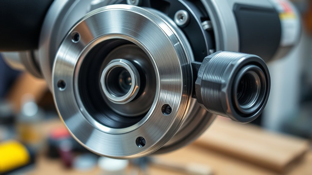
A small flange can create a serious safety problem when it is missing, damaged, or installed incorrectly. The angle grinder flange supports and centers the grinding or cutting wheel on the spindle, while a locking flange or nut holds the assembly together. Because these parts and their orientation vary by grinder and accessory, the tool manual and accessory chart must always control the setup.
Quick Answer
An angle grinder normally uses a backing flange behind the wheel and a locking flange or nut in front. The backing flange’s raised pilot often faces the wheel, but the exact orientation, locking-nut position, and guard depend on the grinder and accessory. Follow the model’s manual rather than a universal thick-wheel or thin-wheel rule.
Key Takeaways
- Do not treat the raised side and flat side as a universal grinding-wheel versus cutting-wheel rule.
- Identify the backing flange and locking flange separately before mounting an accessory.
- Match the wheel type, bore, rated speed, flange set, and guard to the exact grinder model.
- Use only the supplied or manufacturer-approved wrench, flange, nut, guard, and adapter system.
- Stop if the wheel wobbles, rubs, will not sit flat, or requires force to fit.
- After installation, hand-spin the wheel and complete the manufacturer’s recommended no-load test in a clear area.
At a Glance
| Time Required | About 5–10 minutes for inspection and installation |
| Difficulty | Easy when the manual, wheel, guard, and original hardware are available |
| Tools Needed | Grinder manual, supplied pin or hex wrench, clean brush or cloth, correct guard, eye and face protection |
| Cost | No cost for inspection; replacement flange and nut prices vary by model and manufacturer |
What Is an Angle Grinder Flange and Its Purpose?
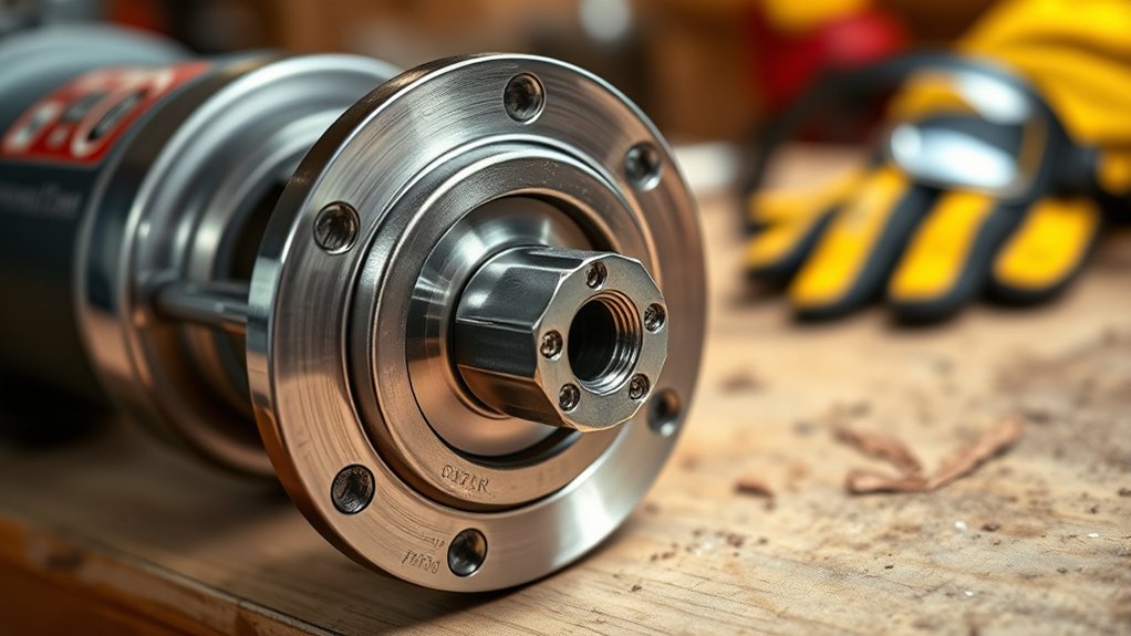
An angle grinder flange supports an approved grinding, cutting, sanding, or polishing accessory on the grinder spindle. A conventional mounting system usually has two separate clamping parts:
- Backing flange or inner flange: Sits behind the wheel, supports it, and often includes a raised pilot that centers the wheel bore.
- Locking flange, outer flange, or lock nut: Threads onto the spindle in front of the wheel and clamps it against the backing flange.
Manufacturers do not always use the same part names. A manual may call the rear part an inner flange, backing flange, or wheel flange. The front part may be called a lock nut, locking flange, clamp nut, or outer flange. Identify both parts in the exploded diagram or accessory chart before installing a wheel.
A correctly matched flange set helps the wheel sit flat and concentric with the spindle. It also spreads clamping force over the area intended by the wheel manufacturer. A damaged, dirty, reversed, or incompatible flange can create wobble, poor clamping, rubbing, or wheel breakage.
Warning: Never use a cracked wheel, bent flange, damaged locking nut, missing guard, improvised washer, or accessory with a speed rating below the grinder’s no-load speed. OSHA requires suitable guarding for portable abrasive-wheel tools, and the guard must be positioned to protect the operator from the wheel and possible fragments.
Which Way Does an Angle Grinder Flange Go?
There is no single flange-direction rule that applies to every angle grinder and every accessory. You must determine which part you are handling and then follow the accessory diagram for your exact grinder.
On many conventional grinders, the backing flange’s raised center or pilot faces outward toward the wheel so it can enter and center the wheel bore. That does not mean every raised surface on every locking nut should face the wheel. The outer locking flange may have different approved positions depending on its shape, the wheel, and the manufacturer.
For example, the DEWALT DCG407/DCG408 manual places the backing flange on the spindle with its raised pilot facing the wheel. Its accessory chart shows that backing flange with both non-hubbed depressed-center grinding wheels and Type 1/41 cut-off wheels. The required locking flange and guard are then selected from the chart.
A Makita XAG16/XAG17 manual also warns that mounting the inner flange on the wrong side can cause dangerous vibration. This is why visual guesses based only on wheel thickness are unsafe.
| Accessory | Typical Mounting Arrangement | What Must Be Verified |
|---|---|---|
| Non-hubbed depressed-center grinding wheel | Backing flange, wheel centered on its pilot, and approved locking flange or nut | Wheel type, locking-flange direction, grinding guard, thickness, bore, and rated speed |
| Thin bonded cut-off wheel | Model-approved backing and locking flanges with the cutting-wheel guard specified by the manufacturer | Type 1/41 compatibility, correct closed or cutting guard, wheel bore, flange profile, and no side grinding |
| Diamond cutting wheel | Approved flange set or threaded connection listed for the wheel and grinder | Rotation arrow, cutting guard, material rating, arbor fit, and maximum speed |
| Hubbed grinding or flap wheel | Accessory hub threads directly onto a matching spindle; the backing flange may need to be removed | Exact spindle thread, guard, wheel diameter, rated speed, and manufacturer approval |
| Sanding or polishing disc | Approved backing pad and clamp nut or a model-specific threaded system | Pad rating, accessory rating, nut position, tool speed, and guard instructions |
| X-LOCK or another quick-change wheel | Wheel attaches to the dedicated quick-change interface without a conventional flange nut | Use only wheels made for that interface and confirm that the retention indicators fully engage |
The correct direction is the direction shown for your exact backing flange, locking flange, wheel, and guard—not a universal “raised side for grinding, flat side for cutting” shortcut.
How to Safely Fit Your Flange
Fitting a flange safely begins before the wheel touches the spindle. Read the grinder’s accessory chart and the wheel label. Confirm that the wheel is intended for the material and task, and check that its maximum speed is at least as high as the grinder’s rated no-load speed.
- Disconnect the power. Unplug a corded grinder or remove the battery. Wait until the spindle has stopped completely before pressing the spindle lock.
- Identify the accessory. Determine whether it is a grinding wheel, cut-off wheel, diamond wheel, flap disc, sanding disc, polishing pad, wire accessory, hubbed wheel, or quick-change wheel.
- Confirm grinder compatibility. Match the grinder model, wheel diameter, spindle thread, wheel bore, flange set, guard type, and maximum RPM.
- Install the correct guard. A grinding guard may not be approved for a thin cut-off wheel. Use the cutting-wheel or closed guard required by the manual.
- Inspect every mounting surface. Check the spindle, backing flange, locking flange, nut threads, and wheel for cracks, bends, burrs, deep grooves, chips, rust damage, or embedded debris.
- Clean the contact faces. Use a dry brush or cloth. Do not leave metal chips, abrasive dust, labels, washers, or other material between the wheel and flange.
- Seat the backing flange correctly. Engage its flats, recesses, or keyed features with the spindle exactly as shown in the manual. Never force it into place.
- Place the wheel on the flange. The wheel should sit flat and center on the pilot without rocking. Do not enlarge the bore or use an unapproved reducer or washer.
- Install the locking flange or nut. Position it as shown for that wheel. Start the threads by hand to avoid cross-threading, then tighten it with the supplied or manufacturer-approved wrench.
- Avoid excessive torque. Tighten enough to secure the wheel without distorting the flange or wheel. Use a stated torque value when the manual provides one.
- Turn the wheel by hand. With power still disconnected, check that it clears the guard and turns without rubbing or visible side-to-side movement.
- Complete a protected no-load test. Reconnect power, hold the grinder with both hands, keep yourself and bystanders out of the wheel’s plane, and run it in a clear area for the period stated in the manual. The 2024 DEWALT instructions call for a one-minute maximum no-load test after inspection and installation.
The OSHA Hand and Power Tools guide states that an abrasive wheel must fit freely on the spindle, the nut should hold it without distorting the flange, and the spindle speed must not exceed the maximum operating speed marked on the wheel.
Warning: Stop the grinder immediately if the wheel wobbles, rubs, chatters, makes an unusual sound, or produces severe vibration. Disconnect the power and inspect the entire mounting system. Never try to “run in” a wheel that is mounted incorrectly.
Avoiding Common Flange Mistakes: Key Tips for Safety and Efficiency
Most flange problems begin with a mismatched wheel, incorrect part orientation, contaminated contact surface, or improvised hardware. Avoid these common mistakes:
- Do not assume that a flange from another grinder fits because its threads appear similar.
- Do not confuse the spindle thread with the wheel’s center-hole or arbor measurement.
- Do not reverse a backing flange merely because the wheel is thinner.
- Do not use a grinding guard when the wheel instructions require a cutting guard.
- Do not install a wheel whose rated speed is below the grinder’s rated speed.
- Do not use a cutting wheel for side grinding.
- Do not use ordinary washers, homemade spacers, jam nuts, or unapproved bore reducers.
- Do not press the spindle lock while the spindle is moving.
- Do not strike the nut, flange, wheel, or spindle to loosen a stuck assembly.
- Do not continue using a wheel that rocks on the pilot or requires force to fit.
Keep the side handle installed, position the guard between you and the wheel, secure the workpiece, and direct sparks away from people, flammable material, cords, batteries, and gas containers. The current OSHA portable-powered-tool standard requires a portable grinder guard to be located between the operator and wheel during use.
Pro Tip: Photograph the correct flange, wheel, nut, and guard arrangement before removing an unfamiliar accessory. Keep the photo with the grinder’s model number, manual, and replacement-part list so the setup can be checked during future wheel changes.
Angle Grinder Flange Types and Mounting Systems
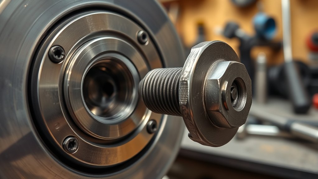
Angle grinder mounting systems are better grouped by how the accessory attaches than by calling a flange simply threaded or threadless.
Products Worth Considering

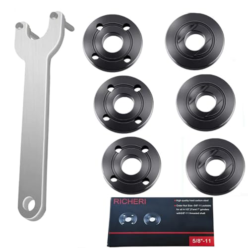
【Value Sets】The grinder nut set includes 1 angle grinder wrench and 6 angle grinder nuts (3 inner flange nuts, 3 outer flange nuts). Please check size and compatibility before ordering. Please contact us with any questions or concerns. We prioritize your satisfaction .

【INCLUDE】Our angle grinder wrench kit include 1 angle grinder wrench, 3 inner angle grinder flange nuts, 3 outer angle grinder flange nuts. We have also provided you with a storage bag for easy carrying and storage.
Replacement part numbers: 224399-1, 193465-4, 224568-4 parts Fit for Makita 9005BZ 9015B 9505BH 9527PB 9527NB 9015DB 9561CV 9016B 9049 9067L 9077SL 9564,GA7021, GA9040S 9" 15A, GA5010Z 10.5A 5", 9557NB, 9558PB, GA6020, 9005B, 9503BH, 9524NB, 9528PB, 9528NB 9" 15A Angle Grinder, etc
Conventional Backing-Flange and Lock-Nut System
This common design uses an unthreaded or keyed backing flange behind the wheel and a threaded locking flange or nut in front. The two parts work together, so neither should be replaced with a random part that happens to fit the spindle threads.
The backing flange may have a raised pilot that centers a non-hubbed wheel. The locking flange may be reversible on some models, but its approved direction depends on its profile and the wheel shown in the manual.
Hubbed or Internally Threaded Accessories
A hubbed grinding wheel, flap disc, wire wheel, or polishing accessory may screw directly onto the spindle. The accessory’s internal thread must exactly match the grinder spindle. Depending on the model, the conventional backing flange may need to be removed before the hubbed accessory is installed.
Never force an accessory that starts crooked or binds after part of a turn. Cross-threading can damage the accessory hub or spindle.
Quick-Change Systems
Dedicated quick-change grinders use a different retention mechanism. For example, the Bosch X-LOCK system mounts a compatible wheel without a conventional spanner wrench or flange nut. An X-LOCK wheel must be used with an X-LOCK grinder; a standard-bore wheel should not be improvised onto that interface.
Note: “Tool-free,” “quick-release,” and “quick-change” do not all describe the same system. Confirm the exact interface name and compatible accessory range in the grinder manual.
How to Match a Replacement Angle Grinder Flange
A replacement flange should be chosen by the grinder’s exact model and manufacturer part number whenever possible. Matching only the spindle diameter or thread is not enough because the pilot height, flange diameter, recess, offset, and guard clearance may differ.
Check all of the following before ordering or installing a replacement:
- Grinder brand and complete model number
- Manufacturer flange or lock-nut part number
- Wheel diameter and approved wheel types
- Spindle thread, such as a model-specific 5/8-11 UNC or M14 thread
- Wheel bore or arbor hole for unthreaded wheels
- Backing-flange pilot diameter and height
- Locking-flange profile and approved direction
- Required guard and clearance
A notation such as 5/8-11 describes a 5/8-inch-diameter spindle with 11 threads per inch. M14 describes a metric spindle-thread system. Neither measurement automatically tells you the bore of an unthreaded wheel. Many applicable North American wheels use a separate 7/8-inch or approximately 22 mm bore, but the grinder manual and wheel label must confirm the fit.
If a “universal” flange listing does not name your grinder model or provide every required dimension, do not assume it is safe. Use an original-equipment part or a replacement explicitly approved for the model and accessory.
Products Worth Considering

[7PCS 5/8"-11 Angle Grinder Nut Wrench Replacement Kit] 1 piece angle grinder wrench and 6 angle grinder nuts (3 inner flange nuts, 3 outer flange nuts) for lock nut removal, wheel/disc replacement.Compatible with most arbor grinders and lock nuts, Perfect for home DIY, workshop projects, and professional grinder parts replacement

【Efficient Quick-Change Design】 Features a convenient quick-change mechanism that allows for fast and tool-free installation and removal of grinding or cutting discs, significantly reducing downtime and improving work efficiency

★Return your hand-held power grinder to its full operating capacity with this angle grinder flange nut for 5/8
Troubleshooting Flange Issues: Quick Fixes and Tips
If the grinder vibrates, binds, rubs, or becomes difficult to service, disconnect it before inspecting the flange system. Do not troubleshoot a mounted wheel while the grinder is plugged in or the battery is installed.
| Problem | Likely Causes | Safe Fix |
|---|---|---|
| Wheel wobbles | Debris on a flange face, wrong bore, wheel not on the pilot, reversed or damaged flange, distorted wheel, or damaged spindle | Remove the wheel, clean and inspect every surface, confirm the part numbers and orientation, and replace any damaged component. Do not operate it to see whether the wobble improves. |
| Locking nut is stuck | Overtightening, heat, debris, cross-threading, wheel binding, or an incorrect nut | Let the tool cool, disconnect power, press the spindle lock only after the spindle stops, and use the supplied pin or hex wrench in the specified direction. Seek service if it will not release normally. |
| Flange will not sit flat | Wrong part, dirt under the flange, burrs, bent flange, or keyed features not aligned with the spindle | Remove and clean it, compare it with the parts diagram, and replace it if distorted. Never hammer or file a flange until it fits. |
| Wheel rubs the guard | Wrong wheel diameter, wrong guard, incorrect flange offset, damaged guard, or wheel not seated | Stop use. Match the wheel, guard, and flange set to the accessory chart and inspect the guard for distortion. |
| Nut repeatedly loosens | Incorrect locking flange, damaged threads, wheel not seated, unapproved washer, wrong rotation setup, or spindle damage | Remove the grinder from service until the entire mounting system has been checked. Do not use thread-locking compound unless the manufacturer expressly requires it. |
| Spindle lock slips or fails | Lock engaged while moving, worn lock pin, damaged gear case, or excessive removal force | Stop using the lock and have the grinder serviced. Do not jam the wheel or gearbox with another object. |
| Original flange is lost | Part removed during a previous accessory change or stored separately | Use the grinder model and official parts diagram to obtain the correct replacement. Do not substitute a generic washer or unrelated flange. |
Warning: Do not use a pipe wrench, locking pliers, hammer, chisel, or improvised spindle stop on a stuck locking flange. These methods can damage the nut, spindle lock, bearings, wheel, or gear case.
How to Maintain an Angle Grinder Flange
Simple maintenance helps the wheel sit flat and keeps the flange threads and contact faces in usable condition.
- Brush abrasive dust and metal particles from the flange after wheel changes and heavy grinding.
- Wipe the spindle threads and flange faces with a clean, dry cloth.
- Inspect the pilot, contact surface, wrench holes, flats, and threads for wear or distortion.
- Keep spare flanges and locking nuts together in a labeled container for the correct grinder model.
- Protect the parts from moisture, loose fasteners, and sharp metal scraps during storage.
- Replace damaged parts instead of grinding, bending, drilling, or filing them back into shape.
A flange does not normally have a fixed replacement interval. Replace it whenever it is cracked, bent, badly corroded, deeply grooved, uneven, cross-threaded, or unable to hold an approved wheel flat and centered.
Frequently Asked Questions
Are 9-Inch Grinders Banned?
There is no blanket U.S. OSHA ban on every 9-inch angle grinder. Major manufacturers continue to offer 9-inch models. However, an employer, contractor, mine, plant, or construction site may prohibit or restrict them because larger wheels, higher power, kickback, noise, and handling demands can increase risk. Follow the site rule even when the tool is legal to buy.
What Is the Purpose of Using the Proper Flange Size on a Grinder?
The proper flange supports the wheel over the intended area, centers its bore on the spindle, provides the required offset, and allows the locking flange to clamp it without distortion. A flange with the wrong pilot, diameter, or offset can cause rocking, rubbing, poor guard clearance, vibration, or wheel breakage.
Which Way Does the Angle Grinder Lock Nut Go?
The correct direction depends on the lock-nut design and accessory. Some locking flanges are reversible, while others have one approved position. Do not decide by wheel thickness alone. Use the mounting diagram or accessory chart for your grinder model and wheel type.
Can I Use an Angle Grinder Without the Backing Flange?
Not with a non-hubbed wheel that requires the backing flange. The wheel needs the approved support and centering surface shown in the manual. A hubbed or quick-change accessory may use a different system, but that does not make the missing flange optional for conventional wheels.
Can I Turn My Grinder Into a Polisher?
Some grinders can use polishing accessories when the tool manual approves them. The backing pad, spindle connection, pad diameter, locking hardware, and speed rating must match. Many fixed-speed angle grinders run too fast for accessories intended for low-speed polishing, so a purpose-built or variable-speed polisher may be safer and easier to control.
What Is a Backing Flange on a Grinder?
A backing flange is the support part that sits behind a non-hubbed wheel. It locates on the spindle and may have a raised pilot that centers the wheel bore. The locking flange or nut then clamps the wheel from the front.
Why Does My Grinding Wheel Wobble After I Tighten It?
Common causes include debris between the wheel and flange, the wrong wheel bore, a wheel that is not centered on the pilot, a reversed or damaged flange, a warped wheel, or spindle damage. Disconnect the grinder and correct the cause before use. Tightening the nut harder is not a safe fix for a wheel that does not sit flat.
How Often Should You Replace an Angle Grinder Flange?
There is no universal time-based replacement schedule. Replace the flange when it is cracked, bent, heavily corroded, deeply grooved, cross-threaded, uneven, or no longer able to support the wheel correctly. Inspect it during every wheel change.
Safety Disclaimer: This article provides general power-tool safety information. Grinder designs, flange profiles, guards, and accessory requirements vary. Always follow the grinder manual, wheel label, workplace procedures, and applicable safety rules. Remove damaged or uncertain equipment from service until it has been checked by a qualified repair provider.
Conclusion
Your angle grinder flange directly affects wheel support, alignment, guard clearance, and safe operation. Identify the backing flange and locking flange separately, then match both parts to the exact grinder, wheel, and guard. Never rely on a universal raised-side or flat-side shortcut. A clean, undamaged, manual-approved mounting system should let the wheel sit flat, turn freely, and pass a controlled no-load test without wobble or rubbing.
Sources
- OSHA 29 CFR 1910.243 — Guarding of Portable Powered Tools — portable-grinder guard position and exposure requirements
- OSHA Hand and Power Tools — abrasive-wheel inspection, spindle fit, flange tightening, speed compatibility, and guarding
- DEWALT DCG407/DCG408 Instruction Manual — backing-flange orientation, accessory chart, guard selection, inspection, and no-load testing
- Makita XAG16/XAG17 Instruction Manual — inner-flange seating and vibration warning
- Bosch GWX10-45PE X-LOCK Angle Grinder — quick-change mounting without conventional flange nuts
- DEWALT DWE4519 9-Inch Angle Grinder — current availability of a commercial 9-inch grinder