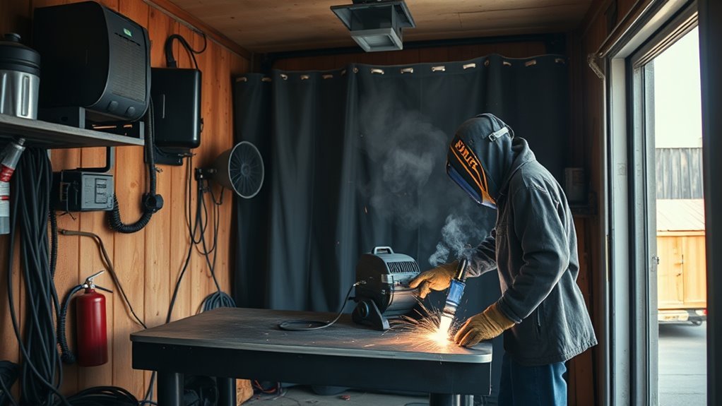
Choosing the wrong MIG welder for car work can leave you with weak fusion, warped panels, or burn-through on thin sheet metal. The right choice depends on the work you plan to do, the machine’s low-end arc control, available input power, wire size, shielding gas, and any vehicle-maker repair requirements.
Quick Answer
For body panels and rust patches, a 120-volt MIG welder in the 130- to 140-amp class is usually enough if it has a smooth low-end arc. For broader automotive work, a dual-voltage 180- to 210-amp machine gives more headroom. Structural repairs must follow the vehicle maker’s repair procedure.
Key Takeaways
- Choose a quality 130- to 140-amp, 120-volt machine for body panels, floor pans, and rust patches.
- Choose a dual-voltage 180- to 210-amp unit when you also expect to weld thicker brackets, exhaust parts, or fabrication projects.
- Low-end arc stability, wire-feed control, and support for .023- or .024-inch wire matter more on thin sheet than maximum output alone.
- Use the welder’s setup chart and test on matching scrap instead of relying on one universal amperage number.
- Use 75% argon and 25% CO2 with solid steel wire for most indoor mild-steel bodywork.
- Follow the vehicle-specific body repair manual before welding any structural, high-strength-steel, aluminum, hybrid, or electric vehicle component.
At a Glance
| Bodywork-Only Choice | 130–140A maximum output, 120V input, smooth low-end short-circuit arc |
| Best All-Around Choice | Dual-voltage 180–210A class for panels, exhaust, brackets, and general fabrication |
| Typical Thin-Steel Setup | .023- or .024-inch ER70S-6 solid wire, DCEP polarity, 75/25 argon-CO2 |
| Structural Repairs | Use only the process, joint, wire, gas, and test procedure specified by the vehicle maker |
What’s in This Article
- Recommended MIG Welder Sizes for Automotive Repairs
- How Material Thickness Affects Welder Selection
- Choosing 120V or 240V Input Power
- Vehicle Welding Safety Before You Start
- Must-Have Features in an Automotive MIG Welder
- Understanding Duty Cycle
- Choosing Wire, Polarity, and Shielding Gas
- Troubleshooting Common MIG Welding Problems
- MIG Welder Maintenance Tips
- How to Make the Final Choice
- Frequently Asked Questions
- Conclusion
- Sources
Recommended MIG Welder Sizes for Automotive Repairs
Start by matching the machine to the thickest work you expect to perform regularly. A large maximum-output number does not guarantee good body-panel performance. On thin automotive steel, the machine must also start cleanly, feed small wire steadily, and maintain a stable short-circuit arc at its lowest settings.
| Planned Work | Practical Machine Class | What to Prioritize |
|---|---|---|
| Outer panels, floor pans, rust patches, and light sheet-metal work | 120V, approximately 130–140A maximum output | Smooth low-end arc, .023/.024 wire support, fine voltage and wire-speed adjustment |
| Bodywork plus exhaust, tabs, light brackets, and occasional thicker fabrication | Dual-voltage, approximately 180–210A maximum output | 120/240V flexibility, better duty cycle, and .023–.035 wire capability |
| Regular off-road fabrication, heavy brackets, fixtures, or thicker shop projects | 200A-plus machine operated on 240V | Rated output, duty cycle, joint preparation, and manufacturer-rated thickness capacity |
| Frame rails, pillars, rockers, crash structures, or other OEM structural parts | Whatever equipment the vehicle-specific repair procedure requires | OEM process, approved wire and gas, weld location, joint design, and destructive test requirements |
A current 120-volt machine can be rated for thin sheet and still provide around 130 to 140 amps at maximum output. A dual-voltage machine can retain good thin-sheet control while providing more output on 240 volts. For example, current manufacturer guidance lists compact 120-volt and dual-voltage machines for automotive work from light-gauge panels through heavier fabrication, but each machine has its own rated limits and duty cycle.
Do not choose a machine solely by its advertised maximum thickness. That rating may assume ideal joint preparation, a particular process, one welding position, and full input power.
For automotive sheet metal, low-end arc quality and small-wire control matter more than the largest amperage number printed on the front panel.
How Material Thickness Affects Welder Selection
Material thickness affects wire diameter, voltage, wire-feed speed, travel speed, joint preparation, and the amount of output the machine must sustain. It should guide your purchase, but it should not be converted into one universal amperage setting.
A common rule of thumb is approximately 1 amp for every .001 inch of steel thickness. For example, .125-inch steel suggests roughly 125 amps as an initial estimate. However, this is only a rough planning rule. The final settings also depend on wire diameter, shielding gas, joint type, welding position, contact-tip distance, and travel speed.
Most conventional MIG welders use a constant-voltage power source. You normally set voltage and wire-feed speed, while the welding current changes largely with wire-feed speed. Always begin with the chart inside the welder, the owner’s manual, or the wire manufacturer’s data.
| Steel Thickness | Common Solid-Wire Choice | Selection Notes |
|---|---|---|
| 24–20 gauge, about 0.6–0.9 mm | .023 or .024 inch | Best control for outer panels and thin patches; use short, spaced tacks rather than a continuous bead. |
| 18–16 gauge, about 1.2–1.5 mm | .023/.024 or .030 inch | Either size may work. Choose the smaller wire for delicate heat control and .030 for broader shop use. |
| Approximately 1/16–1/8 inch, 1.6–3.2 mm | .030 or .035 inch | A larger machine and 240V input may improve output and duty cycle, especially for longer welds. |
| Above 1/8 inch | Follow the machine and wire charts | Joint beveling, multiple passes, position, and rated output become increasingly important. |
Miller’s sheet-metal guidance recommends .023- or .024-inch wire for most light-gauge work and notes that .030-inch wire may be suitable once the material reaches about 18 gauge or thicker.
Pro Tip: Keep offcuts from the replacement panel and practice the same joint on those pieces. Match the gap, number of layers, position, wire, gas, and work-clamp placement before welding the vehicle.
Choosing 120V or 240V Input Power
Your available electrical service can be as important as the welder’s advertised output. Check the input-voltage and branch-circuit requirements in the machine’s manual before buying.
When a 120V MIG Welder Makes Sense
A 120-volt machine is convenient for garages that do not have a 240-volt receptacle. A well-designed 130- to 140-amp unit can handle typical mild-steel body panels, floor pans, patch panels, and many light brackets.
Its main limits appear during longer welds and thicker fabrication. Full output may also require a dedicated circuit of the size specified by the manufacturer. Do not assume that every household outlet, extension cord, or shared circuit can support the machine safely.
When a Dual-Voltage or 240V Welder Is Better
A dual-voltage machine is the more flexible choice when you expect to move between thin panels and thicker fabrication. It can run on 120 volts for portability and use 240 volts when you need greater rated output or duty cycle.
A 180- to 210-amp dual-voltage machine is a practical all-around class for a home automotive shop. It still needs good low-end control for sheet metal; extra maximum output does not correct a rough or unstable low setting.
Note: Use only the input plug, receptacle, breaker, conductor size, and extension arrangement allowed by the welder manufacturer and local electrical rules. Have a qualified electrician install a new 240-volt circuit.
Vehicle Welding Safety Before You Start
Welding on a vehicle can damage electronics or ignite materials that are hidden behind the panel. It can also change the strength of advanced steels if the wrong process or repair location is used.
Warning: Do not weld a structural vehicle part until you have checked the vehicle-specific body repair manual. Some areas must not be straightened, sectioned, plug welded, or heated. The required process may be resistance spot welding, GMA welding, MIG brazing, rivet bonding, part replacement, or another OEM-specified method.
- Identify the material and approved repair: Confirm the year, make, model, part, steel grade or aluminum alloy, sectioning location, joint design, and approved joining process.
- Follow the OEM power-down procedure: Turn the ignition off and follow the manufacturer’s steps for disconnecting the 12-volt system. Observe the required waiting period for airbags and other retained-power systems.
- Handle hybrids and EVs correctly: High-voltage systems must be disabled and verified according to the vehicle maker’s procedure by a person trained and equipped for high-voltage work. Disconnecting the 12-volt battery alone does not make the high-voltage system safe.
- Protect nearby components: Remove or shield wiring, modules, sensors, fuel lines, brake lines, glass, trim, carpet, headliners, seam sealer, sound deadener, foam, adhesives, and cavity inserts near the heat-affected area.
- Place the work clamp close to the weld: Attach it to clean metal on the part being welded whenever the repair information allows. Do not create a current path through bearings, hinges, suspension parts, electronics, or ground straps.
- Control fire hazards: Keep an appropriate extinguisher ready. Inspect both sides of the panel before, during, and after welding, and maintain a fire watch long enough to catch smoldering material.
- Remove hazardous coatings: Clean paint, rust, plating, adhesive, and undercoating only as far as the repair procedure permits. Restore the specified corrosion protection after the joint has cooled and passed inspection.
- Use ventilation and PPE: Wear a suitable welding helmet, safety glasses, gloves, hearing protection, and flame-resistant clothing. Use source-capture ventilation that removes fumes without pulling shielding gas away from the weld.
I-CAR’s vehicle-protection guidance calls for disconnecting the battery and protecting or removing electronics and combustible materials around the welding area. Its separate hybrid and EV welding guidance stresses following the vehicle maker’s high-voltage disabling procedure.
Warning: Galvanized steel, zinc-rich primers, old paint, plated parts, and other coatings can release hazardous fumes. Identify the coating before heating it and use the ventilation and respiratory controls required for the material and work area.
Must-Have Features in an Automotive MIG Welder
A useful automotive MIG welder should provide control, repeatable wire feeding, and convenient setup. The following features matter more than a decorative display or a long list of secondary processes.
- Smooth low-end short-circuit performance: The arc should start cleanly and remain stable on thin sheet without violent stubbing or excessive spatter.
- Fine voltage and wire-speed adjustment: Infinite controls offer flexible tuning, while well-spaced tapped settings can also work when paired with steady wire feed.
- Support for .023- or .024-inch solid wire: Confirm that the drive roll, liner, contact tips, and gun support the small wire used for thin panels.
- Gas-solenoid and regulator compatibility: The machine must support externally shielded solid-wire MIG, not only self-shielded flux-core wire.
- Easy polarity changes: Solid steel wire normally uses DCEP. Flux-cored polarity varies by wire, so the machine should make the connection clear and accessible.
- A readable setup chart: A door chart or automatic setup system can provide a reliable starting point for wire size, metal thickness, gas, voltage, and wire-feed speed.
- Thermal overload protection: The machine should stop output safely if its rated duty cycle is exceeded.
- Replaceable gun consumables: Tips, nozzles, liners, diffusers, and drive rolls should be readily available.
- Suitable input-power options: Choose 120V for bodywork convenience or dual-voltage capability for broader shop use.
- Aluminum wire-feed support when needed: Automotive aluminum work may require an approved spool gun or push-pull system, the correct liner and drive rolls, pure argon, and vehicle-specific repair training.
A digital display is helpful for repeating settings, but it does not guarantee a better arc. Compare the machine’s rated output, duty cycle, wire-size range, input requirements, replacement-part support, and low-end performance.
Products Worth Considering

Smart Parameter Auto-Calibration (Novice-Friendly): Intelligent synergic control automatically synchronizes wire feed speed with current settings to eliminate setup guesswork. Large vivid digital display tracks real-time voltage, amperage, and WFS measurements instantly.

WELD ANYWHERE: Plug in the Weld-Pak 90i MIG wire feed welder anywhere 120V input power is available; It's designed to use with flux-cored welding wire (1/4” max thickness) or solid MIG wire (3/16" max thickness)
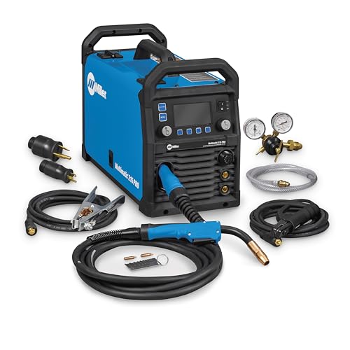
Versatile Performance — Pulsed MIG & Pulsed TIG: This multiprocess welder handles MIG, Pulsed MIG, TIG, Pulsed TIG, and Stick; Auto-Set provides fast settings; powered by continually upgradable USB software
Understanding Duty Cycle: Why It Matters for Welding

The duty cycle tells you how long the machine can operate at a stated output before it needs cooling time. Compare duty-cycle ratings only when the output amperage, voltage, input supply, and test conditions are also shown.
Duty Cycle Explained
Duty cycle is normally expressed as a percentage of a 10-minute period. A 20% duty cycle at a stated output means two minutes of welding followed by eight minutes of cooling. A 40% duty cycle means four minutes of welding and six minutes of cooling at that stated output.
The percentage does not mean the machine can weld every material for that long. It applies at the output printed beside the rating. Operating below the rated output usually allows more arc time, while high ambient temperature, blocked airflow, or low input voltage may reduce practical performance.
Impact on Welding Duration
Most collision-repair panel welds are short tacks, plug welds, or stitches, so a modest duty cycle can be adequate for bodywork. The panel often needs cooling before the welder does.
Duty cycle matters more when you fabricate brackets, weld thicker material, make repeated plug welds, or run longer beads. For mixed automotive and fabrication work, a dual-voltage machine with a stronger rated duty cycle can reduce interruptions.
Never bypass a thermal-protection system or continue welding after the machine indicates an over-temperature condition. Keep its intake and exhaust openings clear and follow the cooling instructions in the manual.
Choosing Wire, Polarity, and Shielding Gas
Wire, polarity, and shielding gas must match the base metal and the repair procedure. Changing one of these variables can change penetration, bead shape, spatter, arc stability, and heat input.
- Mild-steel body panels: Use .023- or .024-inch ER70S-6 solid wire as a common starting choice. Solid wire uses electrode-positive polarity, also called DCEP.
- 75% argon and 25% CO2: This C-25 blend is a common choice for mild steel because it produces a controllable arc, good bead shape, and less spatter than pure CO2.
- Pure CO2: It is less expensive and can provide greater penetration, but it generally creates more spatter and a rougher arc. It is not usually the first choice for delicate panel work.
- Aluminum: Pure argon is the common MIG shielding gas. The machine must also support the correct aluminum wire, gun, drive system, and transfer mode.
- Stainless steel: Match the wire alloy and gas blend to the stainless grade and the power source’s program. Do not use a mild-steel gas recommendation without checking the wire and machine instructions.
- Silicon bronze and MIG brazing: Use them only where the vehicle maker specifies the process. MIG brazing is not a general substitute for welding a structural panel.
- Gas flow: Follow the wire and machine charts. Miller lists 25–35 CFH as a typical starting range for short-circuit MIG. Nozzle size, drafts, joint access, and the manufacturer’s instructions may change the correct flow.
Pro Tip: More gas is not always better. Flow that is too high can create turbulence and draw air into the shielding stream, while low flow or a clogged nozzle can leave porosity in the weld.
Gas-Shielded MIG Versus Flux-Cored Wire
Gas-shielded solid wire is normally the better choice for thin automotive panels in a protected indoor workspace. It provides a controllable short-circuit arc, less slag, and less cleanup.
Self-shielded flux-cored wire is more tolerant of outdoor air movement because it does not rely on an external gas cloud. However, many flux-cored wires produce more spatter, slag, and heat than a small solid-wire setup, making them harder to control on thin exterior panels.
Do not assume every flux-cored wire uses the same polarity. Follow the polarity and parameter information printed on the wire label or data sheet.
How to Troubleshoot Common MIG Welding Problems
MIG welding problems usually come from the relationship between voltage, wire-feed speed, travel speed, wire stickout, gas coverage, polarity, or surface preparation. Change one variable at a time and test the result on scrap.
| Problem | Likely Causes | What to Check |
|---|---|---|
| Burn-through | Excess voltage or heat input, wide joint gap, slow travel, oversized wire, or continuous welding | Use .023/.024 wire, reduce voltage in small steps, improve fit-up, shorten arc-on time, and use spaced tacks. |
| Porosity | Dirty metal, empty cylinder, draft, gas leak, blocked nozzle, incorrect flow, or excessive stickout | Clean both sides, check gas at the nozzle, stop drafts, inspect hoses and fittings, and correct the contact-tip distance. |
| Heavy spatter | Voltage and wire speed are out of balance, polarity is wrong, metal is dirty, or CO2 is being used | Return to the setup chart, verify polarity, clean the joint and work-clamp point, and tune wire speed gradually. |
| Wire stubs into the work | Wire speed is too high for the voltage, voltage is too low, or stickout is too short | Reduce wire speed or raise voltage slightly while staying within the machine chart. |
| Wire burns back to the tip | Wire speed is too low, voltage is too high, tip is worn, or feed is restricted | Correct the parameters and inspect the tip, liner, drive rolls, spool brake, and gun cable. |
| Poor fusion | Insufficient heat, excessive travel speed, poor gun angle, contamination, or an unsuitable joint | Clean to sound metal, verify the joint, increase the parameters within the chart, and confirm fusion on a test coupon. |
| Panel warping | Too much continuous arc time, poor fit-up, or welding one area without allowing it to cool | Use small tacks, move around the repair, maintain the gap, and allow natural cooling between welds. |
| Bird-nesting or erratic feed | Excess drive-roll pressure, wrong roll groove, damaged liner, tight spool brake, or incorrect tip | Match every feed component to the wire and keep the gun cable as straight as practical. |
Lincoln Electric’s MIG troubleshooting guide provides additional checks for feed problems, porosity, poor fusion, and unstable arcs.
Maintenance Tips to Extend the Life of Your MIG Welder
Good maintenance improves wire feeding, gas coverage, and arc stability. Disconnect input power and close the gas-cylinder valve before servicing consumables.
- Clean the nozzle and diffuser: Remove spatter before it blocks shielding-gas flow. Replace cracked or badly distorted parts.
- Inspect the contact tip: Use a tip that matches the wire diameter. Replace it when the hole becomes enlarged, burned, or irregular.
- Check the liner and gun cable: Blow out or replace the liner as directed by the manufacturer. Do not use oxygen for cleaning.
- Set drive-roll pressure correctly: Use only enough pressure to feed the wire without slipping. Excess pressure can deform wire and accelerate liner wear.
- Inspect the work clamp and cables: Repair loose connections, damaged insulation, overheated terminals, and weak clamp jaws.
- Check gas equipment: Inspect the regulator, flowmeter, hose, fittings, and gun connection for leaks or damage.
- Store wire in a dry place: Rust and contamination can damage the liner and cause porosity or unstable feeding.
- Keep cooling passages clear: Remove external dust without opening the machine unless the manual permits it. Internal electrical service should be performed by a qualified technician.
- Secure the gas cylinder: Keep it upright, capped when not connected, and restrained with an approved chain or strap.
Follow the inspection and replacement intervals in the machine and gun manuals. General welding safety practices are covered by ANSI Z49.1 safety resources from the American Welding Society.
How to Make the Final MIG Welder Choice
The best machine is not automatically the model with the greatest maximum output. It is the machine that produces a stable arc on your thinnest work, has enough rated capacity for your thickest routine project, and can run from the electrical service available in your shop.
Products Worth Considering

5 IN 1 MULTIFUNCTIONAL: The MIG-205DS PRO is capable of Gas MIG/Flux Core MIG/Spool Gun Aluminum MIG/Lift TIG/Stick. (additional lift TIG torch required and spool gun required). This unit caters to a wide range of welding applications and meets your various welding needs.

4-IN-1 MIG Welder: The welder machine offers GAS MIG/Flux Core MIG/Lift TIG/ MMA welding modes (Note: WP-17V TIG torch must be purchased separately). It can easily handle welding stainless steel, carbon steel, and even thicker steel materials, meeting diverse welding requirements.

MULTIFUNCTIONAL: A 4-in-1 welder, capable of Flux Core MIG/Gas MIG/ Stick/Lift TIG (need to purchase extra tig lift torch). This unit caters to a wide range of welding applications and meets your various welding needs.
Key Considerations for Amperage and Output
- Define the main job: Body-panel work favors low-end control. Fabrication adds a need for higher rated output and duty cycle.
- Check the complete output range: Compare minimum and maximum output, but also review the manufacturer’s thickness and wire-size charts.
- Read the rated-output line: Maximum amperage alone is less useful than a rating that includes amps, volts, duty cycle, and input voltage.
- Confirm input power: A dual-voltage machine may provide substantially different output on 120 and 240 volts.
- Test the arc: When possible, try the machine with .023/.024 wire on sheet close to the thickness you expect to repair.
Gas Versus Flux-Cored Options
Choose gas-shielded solid wire for thin mild-steel body panels whenever you can control drafts. It produces no flux slag and is generally easier to tune for low heat input and clean panel work.
Choose self-shielded flux-cored wire for suitable outdoor or thicker fabrication only when the wire’s data sheet and the machine support the application. It is not automatically stronger, and it is usually less convenient for finish-sensitive exterior panels.
Importance of Portability
A compact machine is easier to move around doors, quarter panels, wheel openings, and shop bays, but machine weight is only one part of portability. Include the cylinder, cart, leads, gun length, input cord, and required receptacle in your decision.
Consider these points:
- Machine and cart size: Confirm that the complete setup fits through doors and around the vehicle.
- Gun reach: A longer gun can reduce machine movement, but excessive cable length or sharp bends may affect small-wire feeding.
- Gas-cylinder restraint: The cart must hold the cylinder securely and keep the regulator protected.
- Input access: A light machine is not useful away from the wall if the required circuit is unavailable.
- Consumable availability: Choose a gun and drive system with tips, nozzles, liners, and rolls you can obtain locally.
For bodywork alone, a dependable 120-volt 130- to 140-amp machine is often the practical choice. For a shop that also builds brackets, repairs exhaust components, or handles thicker projects, a dual-voltage 180- to 210-amp machine offers more room to grow.
Frequently Asked Questions
What amp MIG welder is suitable for car repairs?
A quality 130- to 140-amp machine is usually sufficient for body panels and rust patches. A dual-voltage 180- to 210-amp model is a better all-around choice when you also expect to weld thicker brackets, exhaust parts, and fabrication projects.
What size MIG welder do I need for car panels?
Choose a gas-capable MIG welder with a smooth low-end short-circuit arc, support for .023- or .024-inch wire, and fine voltage and wire-speed control. A 120-volt machine in the 130- to 140-amp class is commonly enough for panel work.
What kind of welder do I need to weld on a car?
For nonstructural mild-steel bodywork, use a constant-voltage MIG welder that supports solid wire, shielding gas, and .023- or .024-inch consumables. Structural, aluminum, high-strength-steel, hybrid, and EV repairs require the vehicle maker’s approved equipment and procedure.
How many amps do you need to weld a car frame?
There is no safe universal amperage answer for a car frame or unibody structure. Use the vehicle-specific body repair manual to determine whether the part may be repaired and which process, joint, wire, gas, weld location, and test procedure are required.
Is flux-core good for car bodywork?
Flux-core can join suitable steel, but many self-shielded wires create more heat, spatter, and slag than a small gas-shielded solid-wire setup. For thin exterior panels, .023- or .024-inch solid wire with 75/25 shielding gas is normally easier to control.
Can a 120V MIG welder handle automotive work?
Yes. A quality 120-volt 130- to 140-amp welder can handle common body panels, patch panels, floor pans, and light brackets. Its limits are lower rated output and duty cycle on thicker or longer welds.
What wire size is best for automotive sheet metal?
For most light-gauge mild-steel body panels, .023- or .024-inch ER70S-6 solid wire is a good starting choice. It melts with less heat than larger wire and gives the operator more control over a small weld puddle.
Do I need a 240V MIG welder for car work?
Not for ordinary sheet-metal bodywork. A 240-volt or dual-voltage machine becomes useful when you also weld thicker brackets, fixtures, off-road parts, or other fabrication that needs more rated output and duty cycle.
Conclusion
The right MIG welder for car work depends on the work you intend to perform. A quality 120-volt machine in the 130- to 140-amp class is usually enough for body panels and rust repair. A dual-voltage 180- to 210-amp unit is the stronger all-around choice for a garage that also handles brackets, exhaust parts, and thicker fabrication.
Do not size the machine by maximum amperage alone. Check its low-end arc quality, wire-size range, voltage and wire-speed controls, rated duty cycle, input requirements, gas capability, and parts support. Test every setup on matching scrap, and follow the vehicle-specific body repair manual for structural, advanced-steel, aluminum, hybrid, or EV work.
Sources
- Miller — Successfully Welding Sheet Metal With MIG and TIG — thin-sheet wire size, polarity, gas, and heat-control guidance
- Miller — MIG Basics for Automotive Welding Repair — automotive wire selection, settings, technique, and machine classes
- Miller — Shielding Gas for MIG Welding — C-25, pure CO2, argon, and gas-flow guidance
- I-CAR — Vehicle Protection When Welding — battery, electronics, combustible-material, and OEM-procedure precautions
- OSHA — Welding, Cutting, and Brazing — welding hazards, ventilation, PPE, and hot-work resources
- American Welding Society — Free Safety Resources — ANSI Z49.1 welding safety and health guidance