A plasma cutter only works safely when its input power, work lead, torch, and gas supply are connected correctly. The exact plugs, fittings, airflow, and controls vary by model, so use this guide as a setup sequence and treat your operator manual and machine data plate as the final authority.
Last updated: July 19, 2026
Quick Answer
To connect a plasma cutter, leave it switched off, verify the rated power source, install the correct torch consumables, connect the torch and work lead, clamp to clean bare metal, and attach clean, dry air that meets both the required pressure and airflow. Energize the machine only after a complete safety check.
Key Takeaways
- Match the supply voltage, phase, circuit, plug, and generator rating to the machine data plate and manual.
- The work clamp completes the cutting-current circuit; it does not replace the power cord’s protective earth connection.
- Check air volume in CFM or L/min as well as pressure in psi or bar.
- Use clean, dry, oil-free air or only another gas specifically approved by the manufacturer.
- Wear arc-rated eye and face protection, flame-resistant clothing, gloves, boots, and hearing protection.
- Do not cut sealed or previously used containers until a qualified procedure has made them safe.
At a Glance
| Time Required | About 10–15 minutes for a routine setup; longer for a first installation |
| Difficulty | Beginner for normal plug-in setup; electrical plug installation or hardwiring requires a qualified electrician |
| Tools Needed | Operator manual, rated power source, torch and consumables, work lead, air hose, suitable compressor or approved gas supply, regulator/filter, wire brush or grinder, and PPE |
| Cost | Usually no added cost with an existing compatible setup; fittings, filters, electrical work, or PPE may add cost |
Before You Begin
Read the complete operator manual before setup. Plasma cutters differ in input voltage, phase, circuit size, plug type, gas fittings, airflow, torch design, consumables, duty cycle, and automatic controls. A setting that is correct for one machine may be unsafe or ineffective on another.
Gather the plasma cutter, torch assembly, work lead and clamp, approved consumables, a power source that matches the data plate, and an air or gas supply that meets the machine’s flow and pressure requirements. Keep the machine and floor dry, route leads away from walkways, and remove jewelry or loose clothing that could contact hot metal or moving equipment.
Wear safety glasses with side protection under a cutting shield or helmet fitted with the correct filter shade. OSHA lists shade 8 as the minimum for light plasma arc cutting below 300 amps when the arc is visible, but the machine manual or workplace assessment may require a darker lens. Add flame-resistant gloves and clothing, closed work boots, and hearing protection.
Warning: Plasma cutting creates electric-shock, arc-radiation, noise, hot-metal, spark, fire, and fume hazards. Remove combustible materials, keep suitable fire-extinguishing equipment ready, provide effective ventilation, and never cut a sealed container or a container that held flammable or toxic material unless it has been cleaned, vented, tested, and declared safe under an approved procedure.
Note: The OSHA links in this guide describe U.S. workplace requirements. Home users still need to follow the manufacturer’s manual, local electrical and fire codes, and any site-specific safety rules.
Step 1: Verify the Power Requirements and Cable
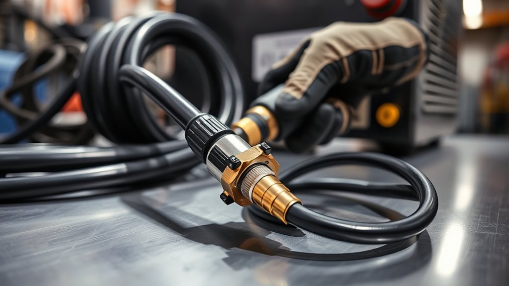
Start with the plasma cutter switched off and disconnected from its energy source. Read the data plate and manual for the required voltage, phase, frequency, input current, branch-circuit protection, receptacle, plug, and generator capacity. Do not assume that two machines with the same output amperage use the same input circuit.
Some plasma cutters arrive with a plug, some use a factory-installed cord without a plug, and others are intended for hardwiring. If a plug must be installed, a circuit must be changed, or the unit must be hardwired, use a qualified electrician. Do not remove the protective-earth pin, use a damaged adapter, or improvise a connection to an undersized circuit.
If the machine has a detachable input cable, seat it only in the manufacturer-designated power connector and secure it exactly as the manual shows. Many machines instead have a fixed input cord, while locking collars are commonly used on torch or work-lead connectors. Never force a connector because its shape appears close.
A plasma cutter’s output amperage does not tell you which wall circuit it needs. Always use the input ratings on the machine data plate.
Step 2: Connect Power Without Energizing the Machine
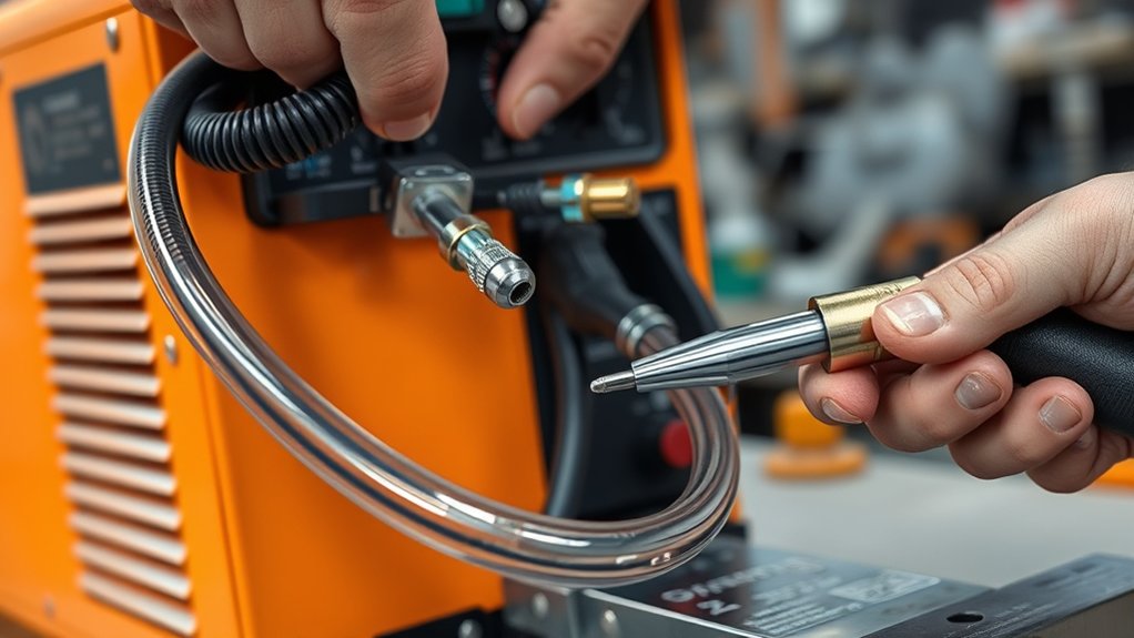
Keep the machine’s power switch in the off position while you make the torch, work-lead, and air connections. If the torch has a lock or disable switch, place it in the safe position. The final power-on step comes only after every connection and safety check is complete.
Plug a factory-equipped power cord into the proper receptacle only after confirming compatibility. Do not treat a building circuit breaker as the normal machine on/off control unless the manufacturer and electrical installation specifically require that method.
| Power Check | What to Confirm |
|---|---|
| Supply compatibility | Voltage, phase, frequency, circuit, and receptacle match the data plate |
| Cable and plug | No cuts, exposed conductors, heat damage, loose pins, or crushed sections |
| Machine controls | Power is off and the torch trigger is locked or disabled |
| Work area | Machine is stable and dry; cables do not create a trip or hot-metal hazard |
| Final startup | Wait until the torch, work lead, gas supply, consumables, and PPE are ready |
Step 3: Attach the Work Clamp to Clean Bare Metal
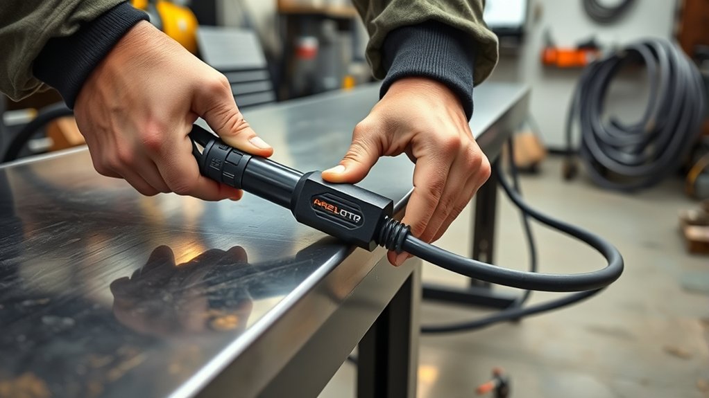
The work lead carries cutting current back to the plasma power supply. People often call it the ground lead, but it is not the same as the protective earth conductor in the input power cord. Both connections matter and serve different purposes.
Connect the work lead to the correct machine receptacle, if it is detachable, and attach the clamp to the workpiece or a properly bonded cutting table. Choose the portion of the metal that will remain after the cut, not the section that will fall away.
Clamp as close to the cut as practical on a clean, dry, bare-metal surface. Remove paint, rust, mill scale, oil, and other coatings from the contact point. Check the clamp jaws, cable lug, connector, and lead for looseness, overheating, broken strands, or damaged insulation.
Pro Tip: Grind or wire-brush a small clamp spot before every important cut. A clean work connection often fixes intermittent starts, unstable arcs, and unexplained cut-quality changes.
Step 4: Connect the Air or Approved Gas Supply
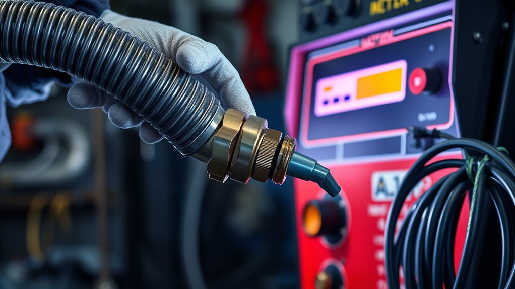
Most portable air-plasma cutters need clean, dry, oil-free compressed air. Some models also permit bottled air, nitrogen, or another specified gas. Use only the gases listed in your manual. Never connect oxygen or any unapproved gas simply because the fitting can be adapted.
Air quality affects arc stability and consumable life. Drain the compressor receiver, inspect the moisture separator, and use the filtration level required by the manufacturer. If oil, water, or dirt reaches the torch, stop and correct the air system before replacing consumables repeatedly.
Attach the Air Line
Locate the gas inlet and use a hose, quick-disconnect, and regulator rated for the supply pressure. Pull back the quick-release collar where applicable, seat the fitting fully, and make sure the hose cannot kink, rub against sharp metal, or contact sparks.
Pressurize the line slowly and check the fittings for leakage using the method approved for the hose and gas system. Do not use an open flame to look for leaks. A hissing fitting, falling gauge, or repeated low-pressure fault needs correction before cutting.
Check Pressure and Airflow
Pressure alone does not prove that the compressor is large enough. The supply must maintain the required airflow while the torch is flowing gas. Compare the compressor’s delivered CFM or L/min at the required pressure with the cutter’s specification, not just the compressor tank size or peak horsepower label.
For example, the legacy Hypertherm Powermax65/85 setup calls for filtered gas at a minimum of 85 psi and no more than 135 psi. The current Powermax85 SYNC specification lists 7.5 scfm at 85 psi for cutting. These figures are examples, not universal settings.
Many modern machines regulate torch pressure automatically after they receive an adequate inlet supply. Others require a manual flow-test mode and regulator adjustment. Follow the model’s flow-test procedure because static pressure can look acceptable and still collapse when cutting begins.
Use a Portable Tank Carefully
A portable receiver tank can work only if it supplies the required pressure and sustained airflow for the entire cut. A small tank may show adequate pressure at rest but drop quickly once the torch begins flowing. Watch the regulator gauge during a test flow, not only before startup.
If the manual permits bottled air or nitrogen, secure the cylinder upright, protect the valve, use the correct regulator, and keep it out of the cutting-current path. Do not substitute a fuel-gas or oxygen setup for an approved plasma gas supply.
| Key Task | Why It Matters | Action |
|---|---|---|
| Tank and hose inspection | Prevents leaks and damaged components | Check the tank, regulator, fittings, and hose before use |
| Pressure setting | Protects the regulator and supports a stable arc | Use the manual’s inlet range and never exceed the maximum |
| Flow capacity | Pressure may collapse during a cut | Verify delivered CFM or L/min while gas is flowing |
| Moisture control | Water and oil shorten consumable life | Drain the receiver and service filters and separators |
Step 5: Attach the Torch Lead and Consumables
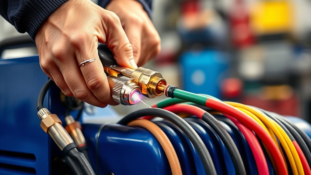
Keep the power off and the torch trigger locked while handling the torch. Inspect the torch body, trigger guard, lead, strain relief, connector, O-rings, and consumable seat. Replace damaged parts with components approved for the torch.
Align any key or index mark before inserting the torch connector. Push it fully into the correct receptacle and secure its collar or locking ring if the design uses one. Do not twist the lead to make a misaligned connector fit.
Install the electrode, swirl ring, nozzle, shield, retaining cap, or one-piece cartridge in the exact order shown in the manual. Tighten hand-installed consumables only as directed. Overtightening can damage parts, while a loose cap may trigger a fault or allow gas leakage.
After assembly, return the torch lock to the position required for the machine’s self-check. Keep your finger away from the trigger until the torch is aimed at the work and you are ready to cut.
Products Worth Considering
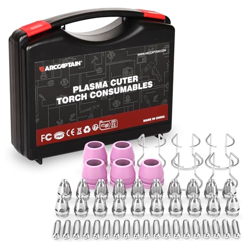
Package Include: 5 Shield Cups, 20 Nozzles .040", 5 Wire Spacer Guides, and 20 Electrodes.

Package Include: 5 Shield Cups, 20 Nozzles .045", 5 Wire Spacer Guides, and 20 Electrodes.

Fit for: SG-55 AG-60 plasma cutter torch head.
Step 6: Select the Correct Tip, Nozzle, or Cartridge
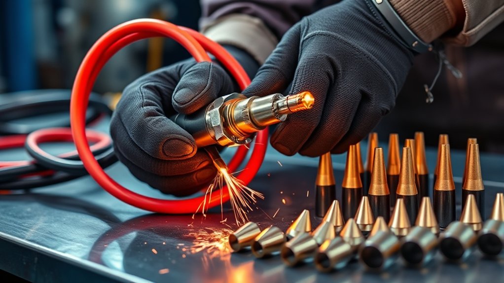
The correct consumable controls arc shape, stand-off, amperage range, and intended process. Match the consumable to the torch model, cutting current, material thickness, and operation. Do not mix parts from different torch families because they appear to fit.
- Use a drag-cutting consumable only when the torch manual allows the shield or tip to touch the workpiece.
- Use a stand-off or mechanized consumable with the specified torch-to-work distance or guide.
- Choose expanded-metal mode or consumables for interrupted cuts when the machine provides that option.
- Use gouging consumables only for gouging, not ordinary plate cutting.
- Use the correct cartridge on automated SYNC-style systems so the machine can identify the process and rated output.
- Replace worn parts as a set when required and inspect the nozzle orifice for distortion, not only visible dirt.
Note: “Drag tip” and “stand-off tip” are common terms, but newer torches may use shields or one-piece cartridges instead. Use the part names and compatibility chart for your exact torch.
Products Worth Considering

[Achieve Precise Cuts] PT31 Plasma Cutting Consumables – Your Essential Tool for Efficient Cutting! Whether you're working with sheet metal, steel, or any other material, superior cutting performance ensure clean, accurate, and smooth cuts.

Package Include: 10 Shield Cups, 50 Nozzles, 20 Swirl Baffle, and 30 Electrodes.

PACKAGE INCLUDED: 5 Pcs Cup-15 Pcs Electrodes-10 Pcs Ring-30 Pcs Tip(Standard)
Step 7: Set the Mode, Amperage, and Gas Controls
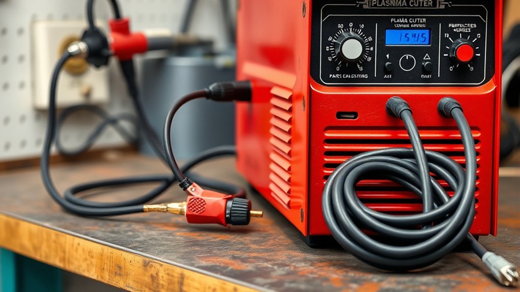
Use the cut chart in the operator manual to choose the cutting mode, consumable, output current, travel speed, and torch height. The material must also be electrically conductive. Mild steel, stainless steel, and aluminum are common plasma-cutting materials, but coatings and alloying elements can change the fume hazard.
A legacy Powermax85 can deliver up to 85 amps, but that does not mean every cut should use maximum output. Thin sheet normally uses a lower-rated consumable or lower current. Some current systems, including Powermax SYNC models, can select mode, gas pressure, and a recommended current from the installed cartridge, though you still need the correct cartridge and cut chart.
Amperage Adjustment Tips
- Start with the cut chart for the metal type, thickness, consumable, and process.
- Use cutting mode for solid plate, expanded-metal mode for interrupted cuts, and gouging mode only with gouging consumables.
- Run the machine’s gas-flow test if the manual provides one, then confirm that inlet pressure stays in range.
- Make a test cut on scrap and judge full penetration, kerf, bevel, top-edge rounding, and dross.
- Change one variable at a time. Dross can result from travel speed, current, stand-off, gas flow, worn consumables, or work-clamp problems, so amperage alone is not the answer.
Metal Type and Coating Considerations
Steel, stainless steel, and aluminum may require different consumables, speeds, gas choices, and fume controls. Remove paint, oil, plating, and heavy rust from the cut path when practical, and identify unknown coatings before heating them.
Use effective local exhaust or other controls to keep fumes out of your breathing zone. Stainless steel, galvanized metal, painted surfaces, and metals with unknown coatings deserve extra caution because cutting can release hazardous airborne contaminants.
Step 8: Complete the Final Check and Make a Test Cut
Only energize the machine after all connections are complete. Use this order unless your operator manual specifies a different sequence:
- Confirm the correct consumables are installed and the torch cap or cartridge is secure.
- Confirm the torch lead and work lead are fully seated.
- Attach the work clamp to clean bare metal on the retained workpiece or bonded table.
- Connect and pressurize the approved gas supply, then check for leaks and adequate flow.
- Remove combustibles, set up ventilation, place screens where other people could see the arc, and keep an extinguisher ready.
- Put on complete PPE and make sure bystanders have suitable eye protection.
- Turn on the plasma cutter using its normal control. Check the display, status lights, mode, current, and gas-pressure indication.
- Use the machine’s gas-test function if available, then make a short cut on scrap of the same material and thickness.
If the machine does not power on, shows a fault, or cannot hold pressure, switch it off before inspecting external connections. Do not open the power supply or bypass an interlock unless the service manual authorizes the work and you are qualified to perform it.
Troubleshooting Common Connection Problems
| Symptom | Likely Setup Causes | Safe First Checks |
|---|---|---|
| No power | Wrong supply, open disconnect, damaged plug, undervoltage, or machine switch off | Turn the machine off; compare the data plate with the supply and inspect the external cord, plug, and approved disconnect |
| Torch will not fire | Torch lock on, loose cap or cartridge, poor work connection, low gas flow, or fault code | Read the fault display, reseat approved consumables, clean the clamp point, and run the gas test |
| Arc starts and stops | Air pressure drops, moisture contamination, loose lead, worn consumables, or clamp on the drop piece | Watch pressure while flowing, service filters, inspect leads, and move the clamp to retained clean metal |
| Heavy dross or rough edge | Wrong speed, current, stand-off, mode, consumable, air quality, or work connection | Return to the cut chart, install the correct consumable, verify dry air and flow, and make one adjustment at a time |
| Breaker trips | Undersized or wrong circuit, excessive extension-cord drop, generator mismatch, or equipment fault | Stop using the machine; compare the supply with the manual and have the circuit or equipment checked by a qualified person |
| Consumables wear quickly | Wet or oily air, incorrect parts, excessive piercing, wrong height, or pressure outside the specified range | Correct the air system and setup before installing another set of consumables |
Common Mistakes to Avoid
- Do not treat a torch-lead locking collar as a universal power-cable connector.
- Do not install a plug, change phase wiring, or hardwire a machine unless you are qualified and the manual permits it.
- Do not defeat the power cord’s protective-earth connection.
- Do not clamp the work lead to paint, rust, a loose table slat, or the piece that will fall away.
- Do not size an air supply by psi or tank gallons alone; verify delivered airflow.
- Do not cut with wet, dirty, oily, or unstable air.
- Do not use worn, mismatched, or incorrectly assembled consumables.
- Do not increase amperage blindly to fix dross or incomplete cuts.
- Do not use an undersized extension cord. Use only a cord type and conductor size approved for the machine, input current, and length.
- Do not cut near flammables, through an unknown coating, or on an unprepared container.
Safe Shutdown and Storage
Release the torch trigger and wait for post-flow to finish. Switch the plasma cutter off, isolate input power as the manual directs, and shut off a bottled or portable gas supply. Relieve hose pressure only by the approved method.
Mark or guard hot metal so another person does not touch it. Inspect the work area for smoldering material, especially behind walls, under the cutting table, and where sparks may have traveled. Coil leads loosely without sharp bends, drain moisture from the compressor system, and store the torch and consumables in a clean, dry place.
Frequently Asked Questions
What safety gear should be worn when using a plasma cutter?
Wear safety glasses with side protection under a cutting shield or helmet with the correct filter shade. Add flame-resistant gloves and clothing, long pants, closed work boots, and hearing protection. OSHA lists shade 8 as the minimum for light plasma arc cutting below 300 amps when the arc is visible, but follow the machine manual and workplace assessment if they require more protection.
How do I maintain a plasma cutter for long-term use?
Inspect the torch, consumables, work clamp, cables, air filter, moisture separator, regulator, and cooling openings on the schedule in the manual. Drain collected water, replace damaged leads, and correct dirty or oily air before it damages another set of consumables. Never open the power supply for internal service unless you are qualified.
Can a plasma cutter be used on painted or rusty surfaces?
A plasma arc can cut through some rust and coatings, but clean metal usually starts and cuts more reliably. Remove contamination from the work-clamp point and cut path when practical. Identify coatings first and control the fumes because heated paint, plating, oil, and unknown residues may release hazardous contaminants.
What is the ideal air pressure for a plasma cutter?
There is no universal pressure. Use the inlet range and flowing-air procedure in the operator manual, and verify the required CFM or L/min at that pressure. As one example, the current Powermax85 SYNC lists 7.5 scfm at 85 psi for cutting, while its inlet system must also remain within the manufacturer’s allowed pressure limits.
How do I troubleshoot common plasma cutter issues?
Start with the fault display and external setup: input power, work-clamp contact, torch connector, consumable installation, air pressure, flowing-air volume, and air quality. Switch the unit off before reseating parts. Use the manual’s fault-code procedure and do not bypass covers or safety interlocks.
Can I run a plasma cutter from an extension cord or generator?
Only when the operator manual allows it. The extension cord must have the correct conductor size, grounding, rating, and maximum length for the input current. A generator must meet the manufacturer’s continuous power and voltage-quality requirements. Undersized cords and generators can cause voltage drop, poor cutting, overheating, or nuisance trips.
Should the work clamp be connected before the machine is turned on?
Yes. With the machine off and the torch trigger locked, connect the work lead and clamp it to clean bare metal on the retained workpiece or a properly bonded table. Complete the torch and air connections before energizing the cutter, unless your model’s manual specifies a different sequence.
Conclusion
To connect a plasma cutter safely, verify the input power first, keep the machine off while you attach the torch and work lead, clamp to clean bare metal, and supply clean, dry gas at the required pressure and airflow. Then install the correct consumables, use the cut chart, complete the fire and PPE checks, and make a controlled test cut.
The most important rule is to avoid universal settings and improvised connections. Your model’s data plate and operator manual decide the correct circuit, fittings, gas supply, consumables, and startup procedure. Careful setup improves cut quality while reducing electrical, fire, fume, and equipment-damage risks.
Sources
- Hypertherm Powermax65/85 setup guide — torch, gas, work-clamp, power, pressure, and electrician guidance
- Hypertherm Powermax85 SYNC specifications — current input gas quality, pressure, airflow, and output specifications
- Hypertherm: How to plasma cut — setup order, PPE, consumables, work lead, and mode guidance
- OSHA 29 CFR 1910.133 — eye and face protection and minimum plasma arc cutting filter shades
- OSHA 29 CFR 1910.252 — arc-cutting PPE, ventilation, fire prevention, and container precautions
- OSHA 29 CFR 1926.352 — hot-work fire prevention, extinguishing equipment, and container safety