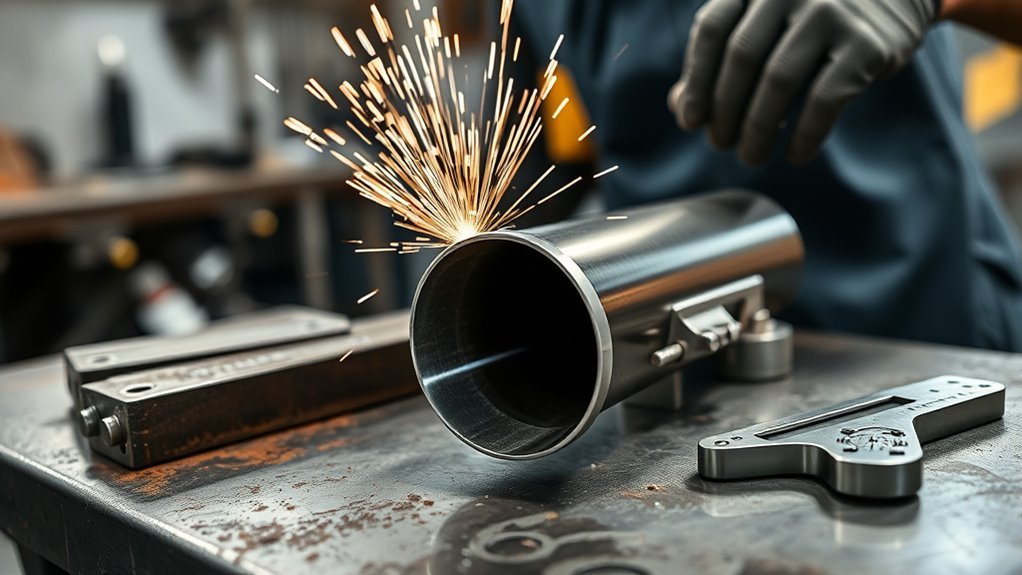
To cut exhaust tubing at an angle, first measure the change in direction you want between the two tube centerlines. For a symmetrical two-piece miter, divide that direction change by two and place one mirrored cut on each tube end. Mark the tubing, clamp it securely, use a metal-rated cutting tool, deburr the edges, tack the joint, and test-fit the complete section before final welding.
Quick Answer
Measure the total direction change between the tube centerlines. For a matching two-piece miter, cut each end at half that angle in opposite directions. Clamp the tubing, cut it with a metal-rated saw or guarded cut-off wheel, deburr it, tack the joint, and confirm clearance before final welding.
Key Takeaways
- Measure the change in direction between the tube centerlines, not the apparent outside sweep of a bend.
- For a symmetrical miter, divide the desired turn by two and make mirrored cuts on the two mating ends.
- Use a metal-cutting saw, band saw, reciprocating saw, or guarded cut-off wheel approved for the tubing material.
- A rotary tubing cutter normally makes a square cut, so it is useful for trimming length but not for cutting a diagonal miter.
- Deburr, clean, tack, and test-fit the complete exhaust section before making final welds.
- Support the vehicle with a lift or correctly rated jack stands, never with a hydraulic jack alone.
At a Glance
| Time Required | 30 minutes to 2 hours, depending on access, the number of cuts, and how many test fits are needed |
| Difficulty | Moderate; accurate angle calculation, secure work holding, and repeated test fitting are essential |
| Tools Needed | Angle finder, marker or scribe, masking tape or wraparound guide, clamps or vise, metal-cutting saw or guarded cut-off wheel, file, deburring tool, measuring tape, PPE, and welding equipment if the joint will be welded |
| Cost | Low when suitable tools are already available; higher when a metal-cutting saw, welding equipment, bends, or replacement tubing must be purchased |
Warning: Let the exhaust cool completely before working. Chock the wheels, apply the parking brake, and use a properly rated lift or jack stands at the vehicle maker’s approved support points. Never work under a vehicle supported only by a hydraulic jack. Cutting and welding create sparks, sharp metal, noise, fumes, and fire hazards. Wear eye and face protection, gloves, hearing protection, and flame-resistant clothing. Keep fuel, brake lines, wiring, upholstery, solvents, and other combustible materials protected from heat and sparks.
Measure the Exhaust Bend You Actually Need
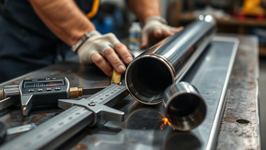
Start by measuring the change in direction between the centerlines of the two tube sections. Do not estimate the angle from the long outside edge of an existing bend. The outer sweep can make a small change in direction look much larger than it is.
The measurement you need is the angle through which the exhaust path must turn. Once you know that number, calculate the cut angle based on the joint you are making.
Calculate the Miter Cut Angle
For a symmetrical joint made from two pieces of the same tubing, use this formula:
Cut angle on each mating end = total desired direction change ÷ 2
| Desired Turn | Cut on First Tube | Cut on Second Tube |
|---|---|---|
| 15 degrees | 7.5 degrees | 7.5 degrees, mirrored |
| 30 degrees | 15 degrees | 15 degrees, mirrored |
| 45 degrees | 22.5 degrees | 22.5 degrees, mirrored |
| 90 degrees | 45 degrees | 45 degrees, mirrored |
For example, if the exhaust path must turn 27.5 degrees, each matching end in a symmetrical joint needs a 13.75-degree cut. Cutting both ends at 27.5 degrees would create approximately twice the intended change.
Saw scales do not all display angles in the same way. Some show degrees away from a square 90-degree cut, while other fixtures reference the blade or fence differently. Confirm the setting on a scrap piece before cutting your final tubing.
Measure an Asymmetrical Joint
The half-angle formula applies when the two mating pieces share the angle equally. It does not apply automatically when one pipe must remain square, one side has already been cut, or the joint meets an existing flange or component at a fixed angle.
For an asymmetrical joint, hold the two pieces in their intended positions and transfer the actual mating plane with a template, contour gauge, cardboard pattern, or direct scribe line. The goal is for the two cut faces to meet with an even gap around the joint.
Check Length and Clock Position
Angle is only part of the layout. Tubing that already has a bend must also be rotated, or clocked, correctly. A joint can have the correct miter angle and still point in the wrong direction.
Draw a witness line along the top or side of both pieces before cutting. Extend that line across the proposed joint so you can restore the original rotation during assembly.
Allow for the width of the blade or cut-off wheel, known as the kerf. Mark which side of the line is waste, then keep the blade on the waste side so the finished section does not end up short.
Mock up the pipe beneath the vehicle before making a final-length cut. Verify clearance around the chassis, floor, axle, suspension, driveshaft, transmission linkage, fuel lines, brake lines, wiring, and heat shields.
Gather Tools for Cutting Tubing at an Angle
You need an angle finder or digital level, a measuring tape, and a fine marker, paint pen, chalk, or scribe. A strip of masking tape, paper, or a commercial pipe wraparound helps carry a straight reference line around the tube.
Choose a cutting tool designed for metal and suitable for the tubing diameter, wall thickness, and material. Read the tool and blade instructions before use. A blade that fits the arbor is not automatically safe for the saw, its speed, or the material.
Use a sturdy vise, chain vise, or clamps that prevent the tubing from rolling. Support long sections on both sides of the cut so the offcut cannot drop, pinch the blade, or pull the work out of alignment.
Products Worth Considering

Materials: Pipe wrap made out of flexible gasket material with good resistance to heat and cold. Asbestos Free.

PREMIUM PIPE MEASURER - Jackson Safety's Wrap-A-Round pipe marking tool is designed for pipe fitters and welders as economical measuring tool for marking straight lines around pipes

Scale Design: Pipe wrap around printed with a scale in inches, inch chart, tangent chart and other useful markings.
Marking Angles Accurately
Measure the required centerline turn while the tubing is held in its intended installed position. Transfer the calculated cut angle to the pipe, then mark the high point, low point, and both side points of the diagonal cut.
Connect those points with a flexible strip of paper, a pipe wraparound, or several short reference marks. A round tube turns a straight diagonal plane into a curved-looking line on its surface, so one freehand mark on the visible side is not enough.
Recheck the angle, cut location, waste side, and tube clocking before switching on the tool. Mark the joint number when several similar pieces are being fabricated.
Choosing Cutting Tools
| Tool | Best Use | Important Limitation |
|---|---|---|
| Metal-cutting cold saw or chop saw | Fast, repeatable bench cuts | The saw, blade, speed, vise, and guard must be approved for the metal being cut |
| Horizontal or portable band saw | Controlled cuts with fewer sparks | Use a suitable tooth pitch and support the tube so the blade does not snag |
| Angle grinder with cut-off wheel | Installed tubing and irregular layouts | Harder to keep square to the cutting plane; requires a guard, correct wheel, and steady two-handed control |
| Reciprocating saw | Restricted access beneath a vehicle | The blade can wander unless the pipe is well supported and the cut is guided carefully |
| Rotary tubing cutter | Square trimming cuts on suitable tubing | It follows the circumference and does not make a diagonal miter cut |
| Tubing notcher | Fishmouth joints where one tube meets the side of another | It is not normally needed for an end-to-end exhaust miter |
Do not assume a woodworking miter saw can cut steel tubing. Some manufacturers specifically prohibit ferrous-metal cutting with their woodworking saws. Check the manual for the exact model. A purpose-built metal-cutting saw, such as a guarded cold saw with a proper vise, is the safer bench option.
Pro Tip: Wrap masking tape or a paper strip around the tubing and align its edges before marking a square reference line. For an angled cut, use that square line as a datum, then measure the required miter from it. This is more reliable than trying to place a diagonal strip around the tube by eye.
Mark the Cut Line for a Clean Fit
Complete the layout in a fixed order so the angle, length, and rotation do not become mixed up.
- Mock up the route. Hold the tubing where it must run and mark the approximate joint location.
- Measure the centerline turn. Use an angle finder, digital level, or straight reference pieces aligned with both tube sections.
- Calculate the cut. Divide the turn by two for a symmetrical two-piece miter.
- Mark the finished length. Allow for overlap in slip joints, clamp position, and the width of the blade or wheel.
- Add clocking marks. Draw a witness line across the joint so the tube can be reassembled at the same rotation.
- Mark the waste side. Add an X to the material being removed.
- Verify the complete layout. Check the angle, length, orientation, and tool clearance before cutting.
When the pipe contains several bends, label each joint and note which face points forward, rearward, upward, or toward the center of the vehicle. This prevents similar-looking pieces from being reversed during tack welding.
Make the Angle Cut on Exhaust Tubing
Remove the tubing from the vehicle and cut it on a bench whenever practical. Bench cutting gives you better clamping, visibility, body position, and control. Cutting beneath a vehicle should be reserved for situations where removal is not practical and all nearby components can be protected.
Before cutting, inspect the blade or wheel for damage and confirm that its diameter, type, arbor, and maximum speed match the tool. Keep all guards installed. Direct sparks away from yourself, the vehicle, fuel and brake lines, wiring, glass, painted panels, batteries, solvents, and combustible materials.
OSHA’s angle-grinder safety guidance recommends proper guarding and personal protective equipment when using abrasive wheels.
Cut With a Metal Saw
- Clamp the tubing against the saw’s fence or vise without crushing it.
- Support the long end and offcut so neither side can move as the cut finishes.
- Align the blade on the waste side of the layout line.
- Bring the blade into the tubing gradually and keep a steady feed.
- Do not twist the tubing or force the blade sideways.
- Let the blade stop before lifting the work from the vise.
Cut With an Angle Grinder
Use a thin cut-off wheel intended for the tubing material. Keep the factory guard and side handle installed. Hold the grinder with both hands and position your body outside the wheel’s plane.
Score the entire visible line lightly before cutting through the wall. Rotate the loose tubing in the vise when possible instead of trying to cut through the full diameter from one side. If the tube is installed, make several controlled passes and stop before the wheel reaches protected components behind the pipe.
Do not push hard enough to flex or bind the wheel. Abrasive wheels cut more accurately when the tool remains aligned with the cut plane.
Cut With a Band Saw or Reciprocating Saw
Select a fine-tooth metal blade that keeps several teeth in contact with the thin tube wall. Clamp the tubing close to the cut to reduce vibration. Start slowly so the blade does not skate across the curved surface.
A reciprocating saw is useful in confined areas, but it is easier for the blade to wander. Leave a small amount of material outside the line when accuracy is difficult, then dress the edge back to the mark with a file or grinder.
The cut does not need to be fast. It needs to stay on the correct plane and leave enough material for a tight, even joint.
Deburr the Edges Before You Weld
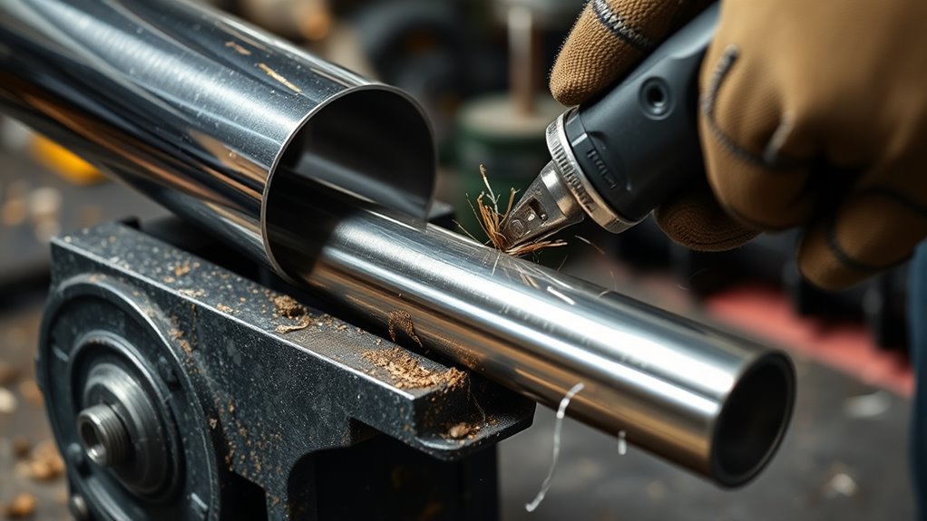
Remove burrs from the inside and outside of both cut ends. Use a file, deburring tool, flap disc, or suitable abrasive until the edges are smooth and the two faces meet evenly.
Check the inside diameter for a lip created by a rotary cutter, saw blade, or abrasive wheel. A large inward burr can disturb fitment and reduce the opening at the joint.
Clean the weld area to bare, sound metal. Remove oil, grease, paint, rust, cutting residue, and coatings from the immediate joint area with a cleaner that is suitable for the material and fully evaporates before welding.
Do not weld over wet solvent, and do not use chlorinated brake cleaner near welding or hot work. Follow the cleaner’s label and safety data.
Aluminized tubing has a protective coating that can contaminate the weld if it remains directly in the fusion area. Remove only the coating required for the weld, then protect the completed area with a suitable high-temperature coating after inspection.
Note: Use abrasives and wire brushes reserved for stainless steel when preparing stainless exhaust tubing. Carbon-steel particles transferred from shared tools can contaminate the stainless surface and promote staining or corrosion.
Use Calculated Pie Cuts for Tight Exhaust Bends
A single miter joint creates one abrupt change in direction. When the exhaust needs a tighter or smoother fabricated bend, use several calculated pie-cut joints or install a manufactured mandrel bend.
Do not rely on a universal rule based only on spacing the cuts a certain number of tube diameters apart. Tube diameter, wall thickness, required radius, joint count, wedge angle, and available space all affect the finished bend.
A manufactured bend is usually the better option when there is enough room. It reduces the number of welds, preserves a smoother internal path, and takes less time to fabricate.
Products Worth Considering

Cushion Grip Handles: Features cushion grip handles to provide comfortable, firm control during use. Reduces hand fatigue when using our exhaust tubing cutter.

🔥 【Lasts Longer, Runs stronger】- Made from tough 304 stainless steel that resists rust and heat. Your exhaust will look great and hold up under pressure—season after season.
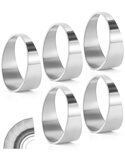
Premium 304 Stainless Steel: Each pie cut is made from high quality 304 stainless steel for maximum durability and corrosion resistance
Calculate the Pie-Cut Angles
Choose the total turn and the number of joints that will share it. Divide the total turn by the number of joints to find the direction change at each joint. Then divide that joint angle by two to find the cut on each mating face.
Example: You need a 30-degree turn made from three equal joints.
- 30 degrees ÷ 3 joints = 10 degrees of direction change per joint
- 10 degrees ÷ 2 mating faces = a 5-degree cut on each face
More joints create a smoother-looking bend but add more cutting, alignment, welding, and opportunities for distortion or leakage.
Make Matching Pie Cuts
Mark every segment from the same reference line so the pieces remain in one plane. Label the segments in order before separating them.
Keep the opposing cut faces matched. A small error repeated through several joints can move the outlet far from its intended position.
Place the pieces against a flat reference surface or simple fixture during assembly. Confirm that the inside edges do not overlap and that the internal opening remains clear.
Test Fit Tight Bends
Tack each joint in several evenly spaced places instead of fully welding one seam at a time. Check the total angle after every few tacks.
Place the assembly beneath the vehicle and inspect the full route. If the bend is wrong, cut or adjust the tacks before final welding. Correcting a fully welded segmented bend takes much longer and may shorten the assembly.
Replace the pie-cut assembly with a manufactured elbow when the joint count becomes excessive, the internal path is badly stepped, or the available welding access is poor.
Test Fit the Pipe Under the Car
Park on a firm, level surface. Apply the parking brake, chock the wheels that remain on the ground, and support the vehicle with a rated lift or jack stands at the approved lifting points. Follow the vehicle maker’s procedure, especially on vehicles with air suspension, active suspension, high-voltage systems, or unusual lifting points.
NIOSH safety material advises using proper jack stands and not relying on a jack as the vehicle’s only support. See its vehicle jack and stand safety guidance.
Fit the cut tubing with the clamps, flanges, slip joints, hangers, flex sections, resonators, mufflers, and converters that affect its final position. A loose pipe held by hand may sit differently after the full system weight is attached.
Check the following areas:
- Floorpan, frame rails, crossmembers, and body panels
- Suspension links, axle, driveshaft, and steering components
- Transmission and shift linkage
- Fuel tank, fuel lines, brake lines, and wiring
- Heat shields, plastic trim, rubber mounts, and sound insulation
- Oxygen sensors, sensor wiring, catalytic converters, and flex joints
- Tailpipe position and its exit outside the vehicle body
Walker advises neutralizing the exhaust so the hangers and isolators are not carrying excessive tension. Its general exhaust installation guidance also notes that the system moves and grows as it heats.
As a general starting point, Walker suggests approximately 1/4 to 1/2 inch where metal-to-metal contact could occur and 2 to 3 inches from non-metal parts that are not designed for heat. These are not universal specifications. The vehicle maker’s required clearances and existing heat shielding take priority.
Check the pipe at normal ride height whenever possible. Suspension droop on a lift can change axle and driveshaft clearance. Do not place yourself beneath a vehicle while another person lowers it unless an approved lift procedure protects everyone involved.
Fix Clearance Issues Before Final Welding
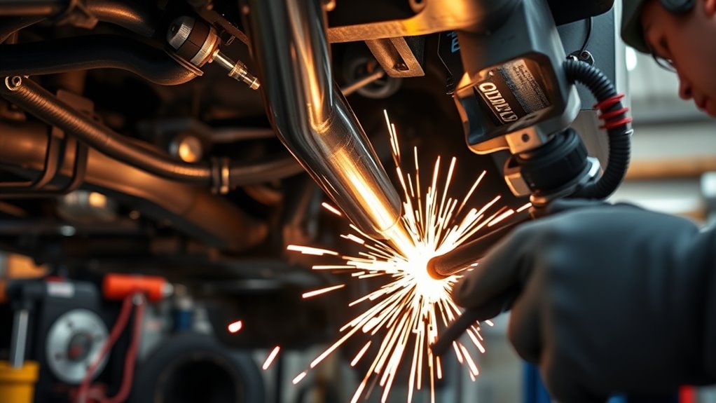
Correct the exhaust route before changing vehicle parts. Rotate the joint, shorten or lengthen a straight section, change the miter, use a different bend radius, or reposition a hanger within its intended range.
Do not casually trim factory heat shields, move a catalytic converter, bend brake or fuel lines, or relocate wiring to make a poor pipe route fit. These parts have safety, emissions, serviceability, and heat-management functions.
If the required route cannot be achieved without altering protected components, stop and consult the vehicle service information or a qualified exhaust fabricator.
Check Hanger Placement
Install the system loosely and inspect every rubber isolator. The hangers should share the load without pulling the tubing hard in opposite directions.
Loosen adjustable clamps and joints, reposition the components until the system hangs naturally, then tighten the connections from the front toward the rear unless the component maker specifies a different order.
Leave room for the system to expand as it heats. A cold system that is already forced against the rear of an isolator may push farther rearward during operation.
Replace damaged, stretched, hardened, or missing isolators. A new pipe cannot remain aligned when the support parts allow excessive movement.
Trim for Linkage Clearance
Move the linkage through its complete normal range with the engine off and the vehicle safely supported. Check the space at each gear position where applicable.
If the pipe interferes, revise the tubing rather than trimming the linkage or forcing the exhaust against another component. Small angle changes near the interference point often move the downstream pipe a significant distance.
When cutting the pipe again, mark the amount and direction of the correction before removing it. Take off less material than the full estimated amount, then test-fit again. It is easy to remove more; it is difficult to restore tubing that has been cut too short.
Tack and Weld the Exhaust Without Contaminating the Joint
Complete as much welding as practical with the assembly removed from the vehicle. This improves access and reduces the chance of damaging wiring, fuel lines, brake lines, insulation, electronics, and interior materials.
Before electric welding on a vehicle, follow the service procedure for the exact year, make, model, powertrain, and battery system. Battery disconnection and electronic-module precautions vary. Some manufacturer guidance requires disconnecting battery cables and placing the welding return clamp close to the weld.
As one example, Ford service information has instructed technicians to disconnect battery cables before electric welding and to attach the welding return as close as possible to the work. See the applicable vehicle service guidance, but do not treat one manufacturer’s instructions as universal.
Keep the welding return clamp on clean metal on the same component and as close to the joint as practical. Do not make the welding current travel through bearings, sensors, suspension joints, cables, or vehicle electronics.
OSHA requires control of hot-work fire hazards and protection from sparks, heat, and slag. Review its welding and cutting requirements before performing hot work.
Tack the Joint First
Align the witness marks and clamp the pieces in the intended position. Place several small tacks around the joint, spacing them evenly.
Recheck the angle after tacking. Thin tubing can pull as each tack cools. Correct the joint before the tacks become large enough to resist adjustment.
Test-fit the complete assembly under the vehicle with all important hangers and connections installed. Do not proceed to final welding until the pipe sits naturally.
Control Heat and Distortion
Use a welding process, filler metal, wire, shielding gas, and settings suitable for the tubing material and wall thickness. MIG and TIG are commonly used for exhaust fabrication, but the correct setup depends on whether the tubing is mild steel, aluminized steel, ferritic stainless, or austenitic stainless.
Move around the circumference instead of concentrating all the heat in one area. Short weld sections and alternating positions can reduce distortion and burn-through on thin tubing.
Do not apply general preheat to ordinary thin-wall exhaust tubing. Use preheat only when a qualified procedure, filler-metal instruction, material specification, or component manufacturer requires it.
Maintain shielding gas coverage and protect the weld from drafts. For high-quality TIG welding of stainless tubing, internal purging may be used to limit heavy oxidation on the root side.
If you are not able to make a sound weld without burn-through, excessive buildup, lack of fusion, or large gaps, have the joint completed by an experienced exhaust welder.
Finish and Recheck the Exhaust Fitment
Let the assembly cool naturally, then remove sharp spatter and inspect the complete circumference of every joint. Look for cracks, pinholes, undercut, incomplete fusion, missed areas, and internal obstructions.
Reinstall the system loosely. Align the tailpipe, muffler, resonator, converter, flex section, hangers, and clamps before final tightening.
Confirm that:
- The pipe does not contact the body, frame, suspension, drivetrain, or heat-sensitive parts.
- The hangers share the load without excessive twist or preload.
- The tailpipe exits outside the vehicle body in its intended location.
- Sensor wiring and nearby hoses remain clipped away from hot tubing.
- Heat shields remain installed and correctly positioned.
- Clamps are placed behind expanded slots or in the position specified by the component maker.
Do not use the final weld to pull a badly fitting exhaust into place. The system should remain aligned when the clamps and hangers are only lightly secured.
Check for Leaks
After all tools, rags, cleaners, and loose parts have been removed, run the engine only in a well-ventilated outdoor area or with suitable exhaust extraction. Never run a vehicle in an enclosed garage without effective exhaust removal.
Listen for sharp ticking or puffing sounds near the repaired joint. Inspect for fresh soot after a short operating period. Keep hands, clothing, hair, and test materials away from hot pipes, belts, fans, and moving parts.
A professional low-pressure smoke test can locate small leaks without relying only on sound. Do not apply uncontrolled compressed air to a sealed exhaust system.
After the first heat cycle and again after the interval recommended by the clamp or exhaust manufacturer, let the system cool and recheck accessible fasteners, clamps, hanger positions, and clearances.
Common Mistakes When Cutting Exhaust Tubing at an Angle
| Mistake | What Happens | Correction |
|---|---|---|
| Using the full turn angle on both ends | The finished bend is approximately twice the intended angle | Divide the turn by two for matching symmetrical cuts |
| Ignoring tube rotation | The outlet points in the wrong direction | Add witness lines before cutting |
| Using a rotary tubing cutter for a miter | The tool follows the circumference and produces a square cut | Use a metal saw or guarded cut-off wheel |
| Using an unapproved woodworking miter saw | The saw, blade, guard, and work holding may not be suitable for ferrous metal | Use a purpose-built metal-cutting saw and follow its manual |
| Cutting exactly on the finished-length line | Blade kerf makes the section too short | Mark the waste side and account for kerf |
| Loose clamping | The tube rolls, chatters, or pulls the blade off line | Clamp close to the cut and support both ends |
| Skipping deburring | The joint has poor fit-up, sharp edges, and trapped residue | Deburr inside and outside before tacking |
| Final-welding before test fitting | Distortion or a small angle error locks the system into a bad route | Tack first and test-fit the full assembly |
| Forcing the pipe with hangers or clamps | The system develops vibration, stress, and premature hanger failure | Neutralize the system before tightening |
| Working beneath a jack-supported vehicle | The vehicle can fall and cause fatal crushing injuries | Use a rated lift or jack stands at approved points |
Frequently Asked Questions
What can I use to cut exhaust tubing?
Use a metal-cutting cold saw or chop saw, band saw, reciprocating saw, hacksaw, or angle grinder with a guarded cut-off wheel. The tool, blade, wheel speed, and work-holding method must be approved for the tubing material and diameter.
How do you calculate an exhaust-pipe miter angle?
Measure the desired change in direction between the two tube centerlines. For a symmetrical two-piece miter, divide that number by two and place one mirrored cut on each mating end. A 30-degree turn uses two 15-degree cuts.
Why are exhaust pipes cut at an angle?
Angled cuts let straight tubing change direction so it can follow the vehicle’s available space. The main goals are proper routing, even joint fit-up, adequate clearance, and a weldable connection. A manufactured mandrel bend is often preferable when space allows.
How do you cut a pipe at any degree?
Measure the required direction change, calculate the mating cut angle, mark the high and low points around the tube, clamp it securely, and follow the line with a metal-rated cutting tool. Deburr the cut and confirm the angle with a test fit before welding.
What cut angle makes a 30-degree exhaust bend?
For a symmetrical joint made from two matching pieces, cut each mating end 15 degrees away from square and mirror the cuts. Together, the two faces create a 30-degree change in direction.
Can a rotary tubing cutter make an angled cut?
No. A normal rotary tubing cutter follows the tube’s circumference and is intended to produce a square cut. Use it for trimming straight length, then use a suitable metal saw or guarded cut-off wheel for a diagonal miter.
Should I cut exhaust tubing before or after test fitting?
Mock up the route before cutting, make the calculated cut, then test-fit again after deburring and tacking. Final welding should only begin after the complete section sits naturally with correct hanger load and clearance.
Do I need to deburr exhaust tubing before welding?
Yes. Remove burrs from the inside and outside edges so the faces meet evenly and no sharp ridge or loose metal remains. Clean oil, coatings, rust, and cutting residue from the immediate weld area.
Do I need to disconnect the battery before welding exhaust tubing?
Follow the welding and battery procedure for the exact vehicle. Many vehicles require battery or module precautions, but the sequence varies and may be more complex on vehicles with multiple batteries, hybrids, electric powertrains, or battery-management systems. Place the welding return clamp close to the joint as directed by the service procedure.
When should an exhaust shop make the cut?
Use a professional shop when the vehicle cannot be supported safely, the cut is close to fuel or brake lines, emissions components must be moved, stainless back purging is required, the tubing is difficult to remove, or you cannot make a sound thin-wall weld without burn-through or leaks.
Conclusion
A clean angled exhaust joint starts with the correct geometry. Measure the required centerline turn, divide it by two for a matching two-piece miter, and confirm how your saw displays that angle before cutting the final tubing.
Mark the waste side and tube rotation, clamp the work securely, use a metal-rated tool, and deburr both edges. Tack the joint and test-fit the full assembly under a safely supported vehicle before final welding.
Do not force the exhaust into place or alter heat shields, fuel lines, brake lines, emissions components, or wiring to compensate for a poor route. When the tubing hangs naturally, clears surrounding parts, and remains aligned after welding, the repair is ready for final inspection and leak checking.
Sources
- OSHA Angle Grinder Safety — grinder guards, sparks, wheel hazards, and personal protective equipment
- OSHA General Requirements for Welding, Cutting, and Brazing — hot-work fire prevention and protection from sparks and heat
- NIOSH: Be an Ace With Jacks — safe vehicle lifting and jack-stand practices
- Walker Exhaust System Installation Tips — hanger neutralization, thermal growth, and general clearance guidance
- DEWALT DW716 Instruction Manual — example of a woodworking miter saw that prohibits ferrous-metal cutting
- RIDGID Model 258XL Pipe Cutter — manufacturer description of rotary pipe cutters producing square cuts