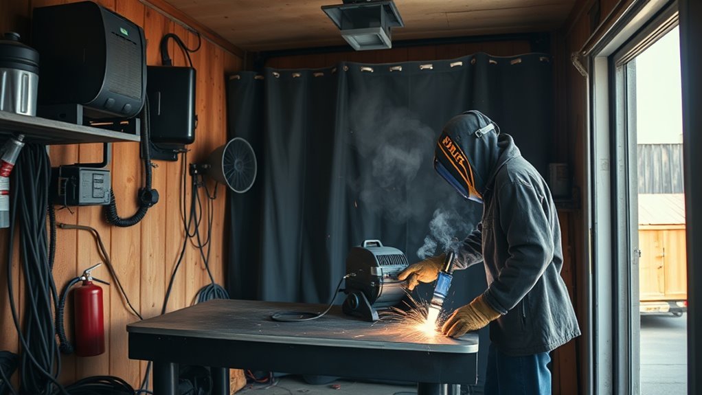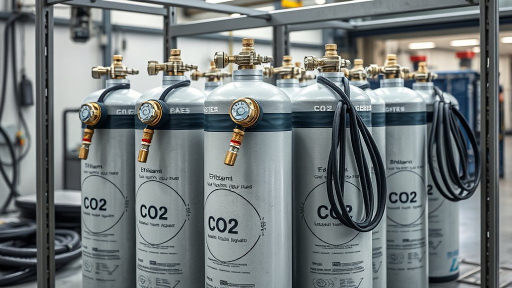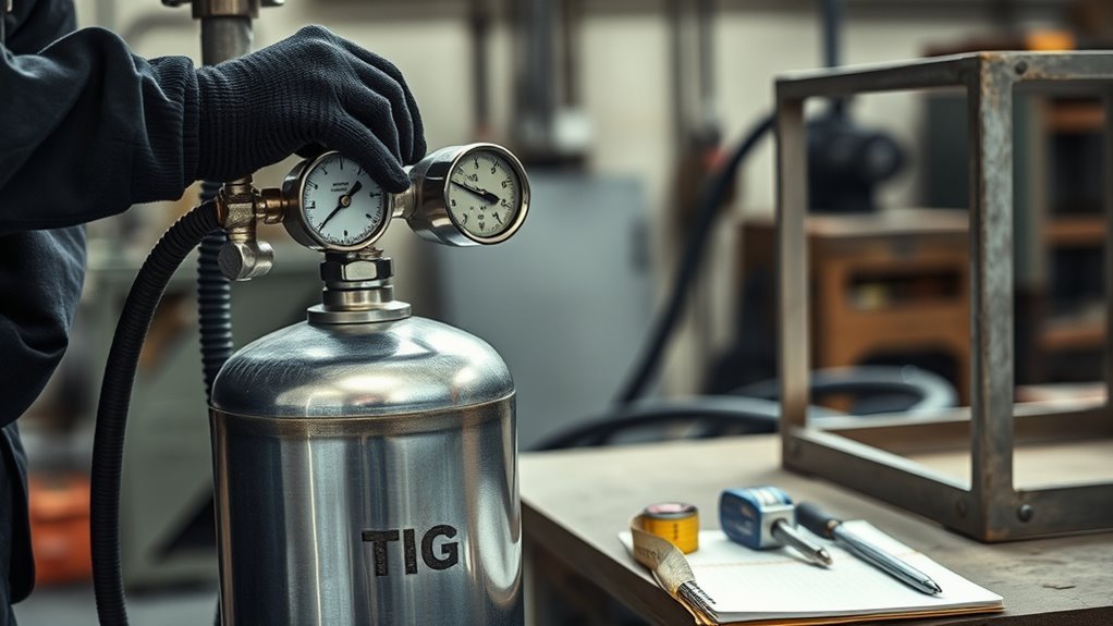
Estimate shielding gas usage by multiplying your set flow rate by your actual arc-on time, then checking that number against cylinder size, wire use, duty cycle, leaks, and your supplier’s current gas rate. This gives you a realistic gas estimate for MIG, TIG, and mixed shop work without treating the full shift as welding time.
Quick Answer
To estimate shielding gas use, set the correct CFH for your process, multiply it by actual arc time in hours, then compare the result with your cylinder volume or gas bill. For example, 30 CFH for 2.4 arc hours uses about 72 cubic feet of gas.
Key Takeaways
- Use arc time, not total shift time, because shielding gas only flows during welding, pre-flow, post-flow, and purge events.
- Start around 20-35 CFH for many MIG jobs and 10-25 CFH for many TIG jobs, then tune for nozzle size, cup size, current, drafts, and weld quality.
- Calculate gas volume with this formula: gas used = CFH × arc hours.
- Estimate cost with your own supplier rate, cylinder rental, delivery charges, and taxes instead of relying on a fixed national price.
- Fast gas loss often comes from leaks, excessive flow, long hoses, cracked fittings, poor solenoids, or post-flow settings that are longer than needed.
At a Glance
| Time Required | 5-15 minutes once you know your flow rate, arc time, and cylinder size |
| Difficulty | Easy for a single job, moderate for a full shop baseline |
| Tools Needed | Flowmeter or flow gauge, timer or weld log, cylinder volume, supplier gas rate, leak-check solution |
| Cost | Depends on your local gas price, cylinder rental, delivery, and how much gas your process uses |
Pick the Right Shielding Gas Flow
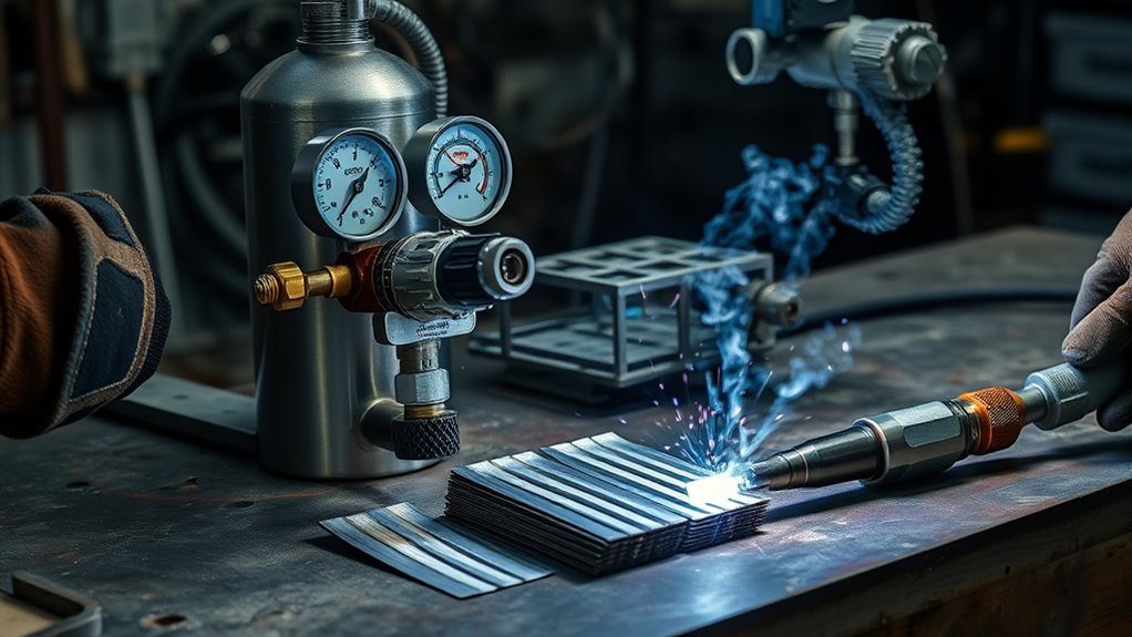
Start with the process. MIG with solid wire often starts around 20-35 CFH in many shop conditions, while TIG often starts around 10-25 CFH depending on cup size, gas lens use, amperage, and joint access. These are starting points, not rules for every weld.
The right gas flow rate depends on weld geometry, travel speed, current, nozzle or cup size, shielding gas type, and air movement around the weld. A small TIG cup on stainless sheet may need far less flow than a high-current spray-transfer MIG weld with a large puddle.
Too little gas allows air into the weld zone and can cause porosity, oxidation, or an unstable arc. Too much gas can create turbulence at the nozzle, which also pulls air into the shield and wastes gas.
Warning: Argon, helium, and shielding gas blends can displace oxygen in low areas, tanks, trailers, pits, and confined spaces. Use ventilation, keep cylinders outside confined spaces, close valves when not in use, and follow your shop safety procedure.
Match CFH to Your Welding Process
Match CFH to the process before you estimate total gas use. Your goal is stable shielding at the puddle, not the highest number on the flowmeter.
| Process or condition | Common starting range | What to check |
|---|---|---|
| Short-circuit MIG on mild steel | 20-30 CFH | Nozzle size, stickout, drafts, and porosity |
| General MIG with solid wire | 20-35 CFH | Joint access, travel speed, and gas coverage at the puddle |
| High-current or spray-transfer MIG | 35-50 CFH | Larger puddle, larger nozzle, and gas turbulence |
| TIG with standard cup | 10-20 CFH | Cup size, tungsten stickout, arc stability, and discoloration |
| TIG with larger cup or gas lens | 15-25 CFH | Laminar flow, post-flow, and backside oxidation |
| Drafty work area | Do not simply crank up flow | Block drafts, use screens, or move the work indoors when possible |
For GMAW, set your shielding gas flow near the low end first, run a short test bead, and inspect the weld. For GTAW, use the smallest flow that keeps the arc stable and prevents oxidation around the bead.
Pro Tip: If the flowmeter is mounted far from the feeder, also check flow at the torch. Long hoses, restrictions, and leaks can make the flow at the cup or nozzle different from the reading at the regulator.
Estimate Gas Use by Arc Time
The basic formula is simple:
Shielding gas used in cubic feet = flow rate in CFH × actual arc time in hours.
If your station runs an 8-hour shift at 30% arc time, the arc is on for 2.4 hours. At 30 CFH, that station uses about 72 cubic feet of gas during arc time:
30 CFH × 2.4 hours = 72 cubic feet
This estimate does not include pre-flow, post-flow, purging, test welds, or leaks. If you use TIG with long post-flow or stainless purge work, add those gas events separately.
For a fast cylinder-life estimate, use this formula:
Cylinder run time in hours = cylinder volume in cubic feet ÷ flow rate in CFH
For example, a 20 cu ft cylinder at 30 CFH lasts about 0.67 hours, or about 40 minutes of gas flow. At 20 CFH, the same cylinder lasts about 1 hour. Your real time may be shorter if you use pre-flow, post-flow, purge gas, or if the system leaks.
Convert Shielding Gas Use to Cost
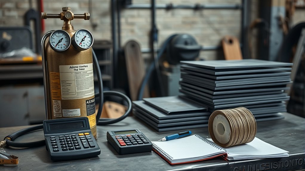
To convert shielding gas use into cost, use your own gas supplier’s current rate. Do not rely on a fixed national price because cylinder exchange, bulk supply, rental, delivery, taxes, and contract pricing can change the number.
Use this cost formula:
Gas cost = cubic feet used × your cost per cubic foot
If your supplier prices gas by CCF, remember that 1 CCF = 100 cubic feet. In that case, divide your cubic feet by 100 first:
CCF used = cubic feet used ÷ 100
Gas cost = CCF used × your supplier rate per CCF
Products Worth Considering

WIDE APPLICATION: It easily connects to Argon, Helium, and Argon/CO₂ mixed gas tanks via the CGA-580 inlet nut. No additional adapters are required. Featuring superior airtight and leak-proof performance, it achieves stable and sealed gas supply with minimal gas loss. This regulator is ideal for MIG/TIG welding, chemical processing, general industrial use, and electronics industry applications.

Professional Ggs Flow Tester / Meter Peashooter Style

Compatible with CGA-580 tanks: Easily attach this Gas Pressure Regulator/Flowmeter to your Argon, Helium, and CO2 tanks with its CGA-580 inlet connector
Gas Usage Cost Basics
For a single weld, your direct gas cost may look small. Across repeated production, leaks, high flow settings, and long post-flow times add up fast.
Here is a clean example using a sample rate. If a job uses 60 cubic feet of gas and your supplier rate is $2.50 per CCF, the gas portion is:
60 ÷ 100 = 0.6 CCF
0.6 × $2.50 = $1.50
That example is only a calculation model. Replace the sample rate with your actual invoice rate.
Calculate Per-Weld Cost
To calculate gas cost per weld, track one batch instead of guessing one bead at a time.
- Record the flow setting in CFH.
- Record the total arc time for the batch.
- Add purge, pre-flow, and post-flow time if they are significant.
- Multiply CFH by total gas-flow hours.
- Convert cubic feet to your supplier’s billing unit.
- Divide the total gas cost by the number of accepted welds.
This gives you a more useful number than total cylinder cost because it separates productive gas use from waste, rework, and idle flow.
Adjust for Wire Speed and Duty Cycle
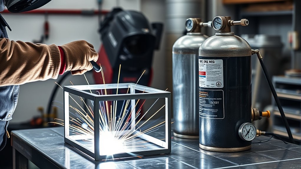
Wire speed matters because it helps you compare gas use against deposited filler metal. This is especially useful in production MIG welding, where one cell may run more wire than another even if both use the same flow setting.
Do not treat wire speed as a direct gas-flow number. Wire feed speed estimates how much wire you deposit per hour. Gas flow estimates how many cubic feet of gas you use per hour. Divide gas flow by deposited wire per hour to estimate cubic feet of gas per pound of wire.
Wire Speed Impact
For example, 0.045-inch solid steel wire at 300 IPM is roughly 8 lb/hr before transfer efficiency and process losses. If your flow setting is 32 CFH, then your rough gas-to-wire ratio is:
32 cubic feet per hour ÷ 8 lb per hour = 4 cubic feet per pound of wire
That ratio helps you compare stations. If one welder uses twice as much gas per pound of wire, check flow settings, leaks, post-flow, and idle gas loss.
Duty Cycle Adjustments
Duty cycle affects total gas usage because it changes arc-on time. A welder at 15% arc time and a welder at 40% arc time can have the same CFH setting but very different gas consumption for the shift.
Use this simple production estimate:
Arc hours = shift hours × arc-time percentage
Gas used = CFH × arc hours
If a 10-hour shift has 25% arc time and the flow is 28 CFH, the estimate is:
10 × 0.25 = 2.5 arc hours
28 × 2.5 = 70 cubic feet of shielding gas
Find Waste From Flow Settings and Leaks
Even a good estimate fails if the delivery system leaks. Check every part of the gas path, from cylinder valve to torch nozzle.
| Check point | Risk | Action |
|---|---|---|
| Flow knob | Excess gas | Reset to the lowest stable flow for the process |
| Hose run | Pressure drop or hidden leaks | Keep hoses short and inspect for cracks |
| Fittings | Leak path | Use approved leak-check solution and repair bubbles |
| Solenoid | Gas flows when idle | Listen for flow after trigger release and repair if needed |
| Nozzle or cup | Poor shielding pattern | Clean spatter, replace damaged parts, and verify flow at the torch |
| Post-flow setting | Unneeded gas use | Use enough post-flow to protect the weld and tungsten, but avoid excessive time |
Document the flow setting, cylinder changes, wire use, and arc time for a few shifts. If gas use rises but wire use does not, you likely have a leak, excessive flow, long post-flow, or poor cylinder tracking.
Compare Cylinder and Bulk Gas Costs
After you tighten flow settings and check for leaks, compare your gas supply options. Cylinder gas can be convenient for low-volume shops, mobile work, and occasional welding. Bulk or manifolded systems can make sense when many stations run every day.
Compare these costs before switching:
- Gas price: Compare the actual cost per cubic foot or per CCF.
- Rental: Include cylinder rental, bulk tank rental, or lease costs.
- Delivery: Add delivery, hazmat, fuel, and handling fees.
- Labor: Count time spent changing cylinders and moving bottles.
- Downtime: Track production delays from empty cylinders.
- Waste: Include leaks, leftover cylinder pressure, and uncontrolled flow settings.
For a small shop, better cylinder tracking may be enough. For a larger shop, a manifold, point-of-use flow controls, or gas monitoring can make waste easier to see.
Products Worth Considering

[Material]304 Stainless steel band, Zinc-Plated 7/16-14 bolt and nut, Steel gasket, Aluminum alloy I-block.
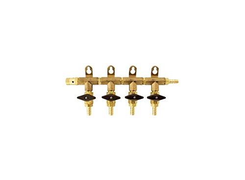
Split your gas line to serve multiple kegs with this manifold

APPLICATION: The ARCCAPTAIN gas pressure regulator can be used with argon, helium, and carbon dioxide gas tanks.
Calculate Savings With Gas Management
To calculate savings with gas management, compare your current measured use with a realistic reduced-use target. Do not assume a percentage. Measure it.
- Record cylinder changes or meter readings for each station.
- Record arc time, shift hours, and wire use for the same period.
- Check every station for leaks and excessive flow.
- Reset flow rates to tested process settings.
- Measure again for the same length of time.
- Convert the difference into cost using your current supplier rate.
This gives you a defensible savings number. It also shows whether the problem is setup, leaks, training, or supply method.
Set Your Shielding Gas Baseline
A baseline is your normal gas use under stable, documented conditions. Set one for each process, wire size, gas blend, and station type.
For each baseline, record:
- Process, material, joint type, and position
- Gas blend and cylinder or bulk source
- Flow setting in CFH
- Nozzle or TIG cup size
- Wire size and wire feed speed for MIG
- Pre-flow and post-flow settings for TIG
- Arc time and shift length
- Cylinder volume or meter reading
- Accepted weld count or deposited wire weight
A good shielding gas baseline is not just a flow setting. It is a record of process, time, wire use, gas volume, and weld quality.
Once the baseline is stable, you can quickly spot drift. If the weld quality stays the same while gas use drops, you found waste. If gas use drops and porosity appears, the flow setting may be too low or the weld area may need better shielding.
Troubleshoot Unusual Shielding Gas Use
If gas use does not match your estimate, use the symptom to narrow the cause.
| Symptom | Likely cause | Fix |
|---|---|---|
| Porosity | Too little shielding, draft, dirty base metal, or gas leak | Clean the joint, block drafts, check flow at the torch, and leak-test fittings |
| Excessive spatter after raising gas flow | Turbulence or wrong welding parameters | Reduce flow to a stable level and tune voltage, wire speed, and stickout |
| Cylinder drains faster than expected | Leak, high CFH, long post-flow, purge gas, or idle flow | Check the solenoid, hoses, regulator, and post-flow setting |
| Good flowmeter reading but poor weld coverage | Restriction, long hose, damaged nozzle, or bad diffuser | Measure flow at the torch and replace worn gas-delivery parts |
| TIG discoloration | Not enough coverage, poor cup angle, short post-flow, or no back purge | Improve torch angle, use a gas lens if needed, and add purge for reactive metals |
Frequently Asked Questions
How do you calculate gas consumption in welding?
Multiply the shielding gas flow rate in CFH by the actual gas-flow time in hours. For most estimating, use arc time instead of total shift time. Add pre-flow, post-flow, purge time, and test welds if they are significant.
How long will 20 cu ft of shielding gas last?
Divide 20 by your CFH setting. At 20 CFH, a 20 cu ft cylinder lasts about 1 hour of gas flow. At 30 CFH, it lasts about 40 minutes. Long TIG post-flow, purge gas, and leaks can shorten that time.
How much shielding gas do I need for MIG welding?
Many MIG jobs start around 20-35 CFH, but the right setting depends on nozzle size, current, transfer mode, wire stickout, joint shape, and drafts. Use the lowest flow that gives clean, stable welds without porosity.
How much shielding gas do I need for TIG welding?
Many TIG jobs start around 10-25 CFH. Smaller cups often need less flow, while larger cups, longer tungsten stickout, gas lenses, and higher amperage may need more. For stainless, titanium, or critical work, watch heat tint and backside oxidation closely.
What is 75% argon and 25% CO2 used for?
A 75% argon and 25% CO2 blend, often called C25, is commonly used for short-circuit MIG welding on mild steel. It gives a smoother arc than straight CO2 in many light and medium steel applications.
Can too much shielding gas cause weld problems?
Yes. Excessive flow can create turbulence at the nozzle or cup, pulling air into the shielding zone. That can cause porosity and oxidation while wasting gas. Raise flow only when testing shows the weld actually needs it.
Conclusion
To estimate shielding gas usage accurately, start with the right CFH for your welding process, multiply it by actual arc time, then add pre-flow, post-flow, purge time, and any known setup losses. Convert cubic feet into cost with your supplier’s current rate, not a generic price. Once you track flow, arc time, wire use, leaks, and cylinder changes, you can set a reliable baseline and cut avoidable gas waste without risking weld quality.
Sources
- OSHA Welding, Cutting, and Brazing — safety topic page for welding hazards, standards, and resources.
- OSHA 29 CFR 1910.252 General Requirements — ventilation, fire prevention, confined-space, and welding safety requirements.
- Miller Electric Guidelines for Gas Metal Arc Welding — manufacturer reference for GMAW setup and process guidance.
- Lincoln Electric Gas Metal Arc Welding Guidelines — manufacturer GMAW guidance and welding variable reference.
- American Welding Society Welding Journal Supplement — technical reference related to GMAW fumes and process conditions.