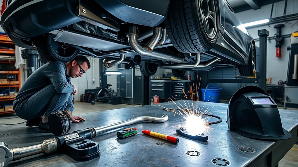
Welding a custom exhaust takes more than joining a few bends under the car. You need to plan the route, protect the vehicle, choose compatible tubing and filler metal, create accurate joints, control welding heat, and support the finished system without forcing it into place. Stainless systems also need an internal argon purge during TIG welding to protect the weld root.
This job is best suited to someone who can already make consistent welds on thin tubing. Poor fit-up, excessive heat, unsafe vehicle support, incorrect electrical isolation, or misplaced emissions components can cause leaks, rattles, damaged electronics, fire, inspection failure, or exhaust gases entering the cabin.
Quick Answer
To weld a custom exhaust, measure and mock up the complete route, prepare tight square joints, place balanced tack welds, then remove sections for final welding when possible. TIG weld stainless tubing with matching filler, controlled heat, and an argon back purge. Reinstall it with neutral hangers, test for leaks, and retain all required emissions equipment.
Key Takeaways
- Measure the actual vehicle and exhaust instead of copying a generic pipe size, bend angle, or hanger position.
- Follow the vehicle maker’s welding and electrical-isolation instructions before striking an arc on the car.
- Make square, clean, close-fitting joints so thin tubing needs less filler metal and less welding heat.
- Back-purge stainless exhaust tubing with argon to protect the inside of the weld from heavy oxidation.
- Use flex sections, service joints, and hangers without preloading or forcing the exhaust into position.
- Repair welded pinholes by cleaning and rewelding them. Do not rely on assembly paste as a permanent weld repair.
- Keep required catalytic converters, sensors, filters, mufflers, and other regulated equipment in compliant positions.
At a Glance
| Time Required | A full day to a weekend for a complete system, depending on access, complexity, equipment, and fabrication skill. |
| Difficulty | Intermediate to advanced. You need safe lifting skills, accurate cutting and fit-up, thin-wall welding experience, and basic knowledge of vehicle electronics and emissions systems. |
| Tools Needed | Lift or rated jack stands, wheel chocks, welding PPE, fume extraction, fire extinguisher, tape measure, calipers, angle finder, marker, tube cutter or saw, belt sander or grinder, deburring tools, clamps, stands, TIG or suitable MIG welder, shielding gas, purge equipment, filler metal, and leak-test equipment. |
| Cost | Varies widely with tubing grade, bends, catalytic converters, mufflers, resonators, flex sections, service joints, hangers, welding gas, and the fabrication equipment you already own. |
Warning: Work only on a cool vehicle supported by a lift or properly rated jack stands on solid ground. Chock the wheels and never work under a vehicle held only by a jack. Welding involves fire, ultraviolet radiation, electricity, sharp metal, hot parts, shielding gases, and hazardous fumes. Keep a suitable fire extinguisher nearby and use local fume extraction.
Before You Start
First decide whether you have the equipment and skill to complete the job safely. Exhaust tubing is thin, and a small fit-up error can lead to burn-through, distortion, internal oxidation, or a leak. Practice on offcuts of the same material and wall thickness before welding the vehicle’s parts.
Check the vehicle maker’s service information before disconnecting power or welding on the vehicle. Welding current can damage modules, wiring, sensors, and restraint-system components. I-CAR recommends keeping the welding current path short, placing the work clamp close to the weld, isolating battery systems as directed, and keeping welding cables away from electronic equipment. See the I-CAR vehicle welding precautions.
Hybrid and electric vehicles require additional high-voltage isolation. Do not assume that disconnecting the 12-volt battery makes an EV or hybrid safe. Follow the exact vehicle-maker procedure, observe the required waiting period, and use a qualified technician when the procedure calls for one.
Remove nearby trim, underbody panels, insulation, oil residue, and other combustible materials. Shield fuel lines, brake hoses, wiring, batteries, rubber parts, glass, and painted surfaces from heat and sparks. Do not weld close to a fuel tank or fuel line unless the vehicle maker’s procedure specifically permits the repair and all required protections are in place.
Stainless welding fumes may contain hazardous chromium compounds. OSHA advises using ventilation that removes fumes from the breathing zone and notes that welding outdoors does not automatically provide adequate protection. Review the OSHA welding-fume guidance before beginning.
Note: Argon is not toxic, but it can displace oxygen. Keep purge and shielding gases out of pits, enclosed garages, vehicle interiors, and other low or confined spaces.
Plan Your Custom Exhaust Layout
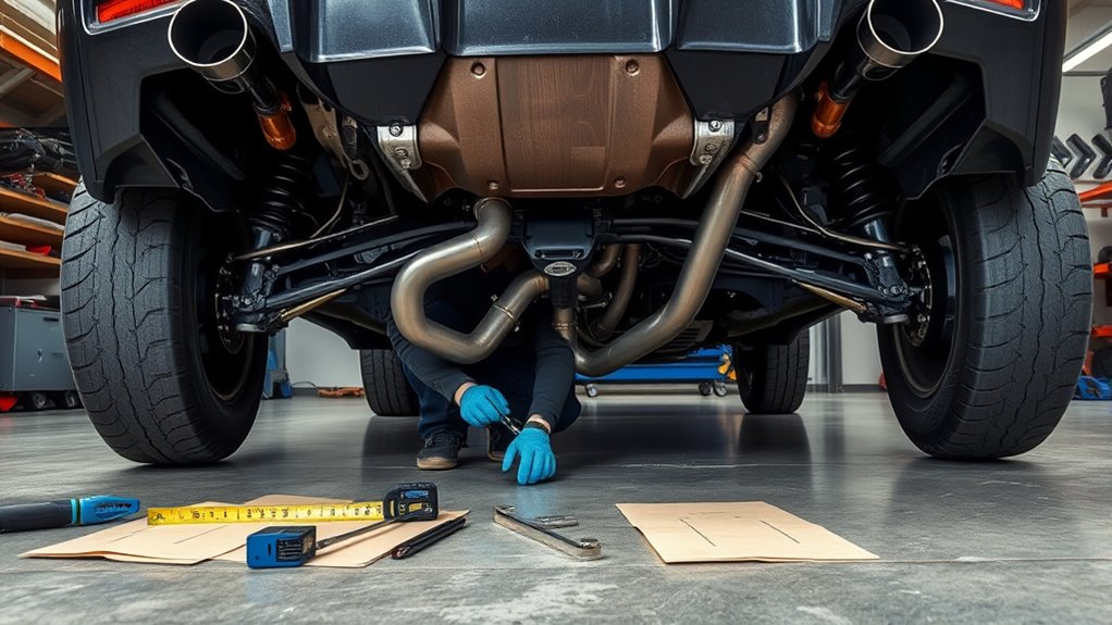
Plan the complete route before ordering bends or cutting tubing. Mark the manifold or downpipe connection, catalytic converters, particulate filters where fitted, oxygen sensors, flex sections, resonators, mufflers, service joints, hangers, and tailpipe exit.
Keep the tubing clear of the driveshaft, steering components, suspension links, axles, brake lines, fuel lines, wiring, plastic panels, rubber mounts, and heat-sensitive parts. Check the full suspension and axle travel rather than judging clearance only at normal ride height.
Leave enough space for the system to expand as it heats. The exhaust should not depend on a rigid hanger or forced flange alignment to stay clear of the body. It also needs enough ground clearance for ramps, speed bumps, suspension movement, and normal vehicle loading.
Choose the Pipe Diameter
There is no single pipe diameter that suits every engine. Required size depends on engine displacement, power, operating speed, aspiration, turbocharger or header outlet, exhaust length, emissions equipment, and the intended use of the vehicle.
For a standard or lightly modified vehicle, keeping the original diameter is often the safest starting point. A smaller pipe can create an unwanted restriction at higher flow rates. A much larger pipe may add weight, reduce ground clearance, complicate routing, and change the sound without producing a useful gain.
For a heavily modified engine, use the engine builder’s recommendation, the turbo or manifold outlet requirements, and test data rather than a generic internet chart. Do not reduce the tubing abruptly at a flange or connector because the step can disturb flow and create a local hot spot.
Select the Route and Components
A single system usually offers simpler routing and lower weight. A dual system may suit the engine layout or packaging, but it requires enough room for two pipes, additional hangers, and balanced component placement.
Choose the number and style of mufflers or silencers and resonators according to the engine, cabin-drone target, available space, track rules, and public-road sound limits. No universal rule says that a street vehicle needs a fixed number of silencers.
Place service joints where the system must be removed for transmission, subframe, axle, or engine work. A fully welded one-piece system may look tidy, but it can become difficult to install or service.
Pro Tip: Draw the route before buying parts. Mark every bend, straight section, sensor bung, flange, V-band, slip joint, flex section, hanger, muffler, and tailpipe exit. The sketch will also help you decide where removable subassemblies should begin and end.
Choose Tubing, Flanges, Flex Joints, and Silencers
Select all major parts before fabrication so the tube diameter, wall thickness, alloy, connectors, and filler metal remain compatible.
Products Worth Considering

【Durable & High-Quality Material】Crafted from premium stainless steel, this 1 inch flexible exhaust pipe offers excellent resistance to heat, corrosion, and wear. Its smooth surface and solid construction ensure long-term use without deformation or cracking — perfect for daily operation in tough environments.

This Universal Custom Exhaust Kit Made of High Quality T304 Stainless Steel with Computerized Mandrel-Bends for Strength and Durability, 16-Gauge Piping Walls

[Material]Made of high quality T304 stainless steel, high strength, long life, corrosion resistance, oxidation resistance.
Compare Exhaust Materials
- 304 or 304L stainless steel: A common choice for custom systems because it offers good corrosion resistance, availability, and weldability. It costs more than basic mild or aluminized steel and requires careful heat control.
- 409 stainless steel: Common in original-equipment exhausts. It provides useful heat and corrosion resistance at a lower cost than 304, although its surface can discolor or develop superficial oxidation.
- Aluminized or mild steel: Easier on the budget and suitable for many repairs or basic systems, but generally less corrosion resistant than stainless tubing.
- 316 or 316L stainless steel: Offers additional resistance in harsh chloride or chemical exposure. It is not automatically a performance upgrade for an ordinary road exhaust.
- Titanium: Lightweight but expensive and highly sensitive to contamination during welding. It requires strict shielding and purging and is not a beginner material.
Confirm the tubing alloy before choosing filler metal. For example, ER308L is commonly used with 304 or 304L stainless, while ER316L is commonly matched to 316 or 316L. Dissimilar joints may require a different filler. Follow the filler manufacturer’s compatibility chart rather than choosing by appearance.
Choose Service Joints
Use welded joints where permanent assembly makes sense. Add removable joints where the exhaust must separate for installation or future repairs.
- Two-bolt or multi-bolt flanges work well when the bolt pattern, gasket, flange thickness, and available space suit the vehicle.
- V-band clamps create compact service joints and simplify repeated removal when both mating flanges are aligned correctly.
- Slip-fit joints allow adjustment and can help accommodate movement, but they need the correct overlap, clamp, and sealing method.
- Ball-and-socket joints can tolerate limited angular movement and are common in some original systems.
Do not place a flange at every joint without a reason. Each extra service joint adds weight, cost, packaging needs, and another possible leak point.
Place Flex Sections and Hangers
A flex section can isolate engine movement from the rest of the exhaust, but it cannot correct a badly aligned system. Install it in the direction and position specified by its manufacturer. It should sit in a neutral position rather than being stretched, compressed, twisted, or used to support exhaust weight.
Place hangers close enough to control the system without making it rigid. Use suitable rubber isolators and position the rods so the exhaust hangs naturally. Walker notes that the isolators should settle into a neutral, straight position as the system reaches operating temperature. Its exhaust installation guidance also recommends tightening gasketed flange hardware evenly.
Position Catalysts and Oxygen Sensors
Retain the original catalytic converters, particulate filters, oxygen sensors, temperature sensors, pressure lines, and other emissions devices unless a legal, approved replacement procedure permits a change.
Record each sensor’s position, angle, distance from the engine, and location before or after the catalyst. Moving a sensor can change its temperature, expose it to condensation, produce inaccurate readings, or trigger a fault code.
Follow the vehicle maker’s requirements first. Bosch also advises mounting compatible lambda sensors where they sample representative exhaust gas, remain within their temperature limit, avoid outside-air influence, and are protected from condensation. See the Bosch LSU 4.9 installation notes for an example of sensor-maker guidance.
Measure the Car and Old Exhaust
Measure from fixed chassis reference points, not from parts that can move. Record pipe centerlines, available width and height, minimum ground clearance, component positions, hanger locations, flange angles, and tailpipe placement.
Measure the Vehicle Underside
Raise and support the car safely, then inspect the complete path from the manifold or downpipe to the tailpipe. Use a tape measure, calipers, flexible ruler, and angle finder to capture diameters, offsets, drops, rotations, and bend angles.
Check:
- Steering movement and driveshaft clearance
- Rear axle and independent-suspension travel
- Brake and fuel line routing
- Heat shields, floorpan dips, crossmembers, and subframes
- Fuel tank and battery position
- Transmission, differential, and service access
- Bumper and body clearance around the tailpipe
Measure at several points because tubing, clamps, and expanded connections may have different inside and outside diameters.
Record the Old Exhaust Specifications
Measure the actual old system instead of assuming it uses a common size. Record the outside diameter, wall thickness when accessible, centerline length, bend radius, flange orientation, sensor location, hanger position, and connector overlap.
Use the existing system as a reference, not as a perfect template. Note any section that hangs too low, touches the body, leaks, restricts service access, or places a tailpipe too close to the bumper.
- Photograph each section before removal.
- Mark front, rear, left, right, top, and sensor orientation.
- Measure between fixed reference points.
- Record the angle of every flange and sensor bung.
- Label parts that will be reused.
Note: Write measurements directly on masking tape attached to each old section. A clear label is more reliable than trying to remember the orientation after the exhaust is on the floor.
Remove the Old Exhaust and Mock Up Parts
Let the exhaust cool completely. Support long or heavy sections before releasing hangers or fasteners so they cannot fall or swing into you.
Apply penetrating oil to rusted hardware and allow time for it to work. Use the correct sockets and support both sides of a joint while loosening it. Heat may help with seized hardware, but open-flame work near fuel, underbody coatings, rubber, or wiring requires additional fire controls and may be unsuitable.
Inspect removed flanges, clamps, hangers, isolators, heat shields, and sensor bungs. Replace distorted flanges, cracked rubber mounts, severely corroded clamps, and damaged flex sections.
Build the new system from one stable reference point, usually the manifold, downpipe, or an existing service flange. Hold each section at its intended ride height with stands, clamps, magnets, or temporary wire supports.
Rotate bends and trim small amounts at a time. Confirm the tailpipe position, service access, component clearance, and hanger alignment before adding permanent welds.
Do not force two misaligned parts together with flange bolts or a flex section. Correct the cut, bend, rotation, or support position until the parts meet naturally.
Prepare the Tubing for Welding
Good exhaust welds begin with accurate cuts and clean metal. Welding cannot reliably hide a crooked cut, large gap, heavy burr, or contaminated surface.
- Cut the tubing square. Use a tube saw, band saw, or suitable cutting tool that leaves a controlled edge.
- Deburr the inside and outside. Remove sharp edges and loose particles that could contaminate the weld or remain inside the exhaust.
- Correct the fit. Dress the cut face until the joint closes evenly around the circumference.
- Clean the weld zone. Remove oil, adhesive, oxide, marking residue, paint, and cutting fluid with a residue-free cleaner approved for welding.
- Prevent cross-contamination. Use dedicated stainless brushes, abrasives, files, and work surfaces when preparing stainless parts.
- Allow solvent to evaporate fully. Never weld while cleaner or vapor remains in or around the tubing.
Miller recommends close fit-up and tools dedicated to stainless because contamination and wide gaps can increase heat input and reduce weld quality. Its stainless tube and pipe welding guide also explains filler selection and argon purging.
Set Up the TIG Welder
- Current: Use the polarity recommended for the material and machine. Stainless and mild-steel TIG welding commonly use direct current electrode negative.
- Shielding gas: For stainless GTAW, 100% argon is a standard shielding choice.
- Back-purge gas: Use clean argon for the inside of stainless tubing unless a qualified procedure specifies another method.
- Filler metal: Match it to the identified base alloy and joint requirements.
- Tungsten and cup: Follow the welder and consumable manufacturer’s recommendations for the current range and access.
- Amperage: Set it according to the actual wall thickness and test the setup on matching scrap.
- Gas flow: Use enough flow for stable coverage without creating turbulence that draws air into the shielding zone.
- Post-flow: Keep the hot tungsten and end of the weld shielded until they cool sufficiently.
Do not copy a single amperage or gas-flow number without considering wall thickness, cup size, joint fit, torch position, gas-lens setup, and the machine’s calibration.
Set Up the Back Purge
Back purging replaces oxygen inside stainless tubing with inert gas while the joint is welded. Without adequate protection, the root can develop heavy oxidation often called sugaring.
- Install purge dams or seal the ends of the section without trapping pressure.
- Place the argon inlet so gas moves through the weld area.
- Provide a separate, unrestricted vent for displaced air and purge gas.
- Allow enough time for the purge to displace the air before welding.
- Maintain a gentle purge during the weld.
- Do not seal both ends of a tube while it is being heated or welded.
Warning: A purged tube must have a vent. Heating a sealed tube or component can create dangerous pressure. Route purge gas into a well-ventilated area and keep it away from pits and enclosed spaces.
Tack Weld the Exhaust Sections
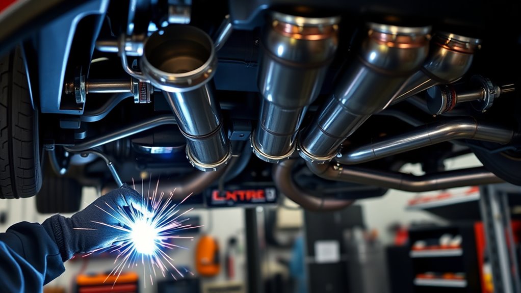
Tack welds hold the final orientation while still allowing you to cut and correct a joint. Keep them small enough to remove without damaging the tubing.
Position Sections Precisely
Align the tubing centerlines and check the rotation of every bend. Hold catalytic converters, mufflers, resonators, flex sections, flanges, and sensor bungs in their intended orientation.
Before tacking, confirm that:
- The joint faces meet evenly.
- The tubing is not forced sideways.
- Flange faces remain parallel and square.
- Sensor bungs point in the required direction.
- Flex sections remain neutral.
- Hangers are not carrying side load.
Check Alignment and Joint Fit
Use the smallest consistent gap that suits the material, wall thickness, and welding procedure. Thin exhaust tubing generally benefits from close, square fit-up. A large gap demands more filler and heat and increases the risk of burn-through or distortion.
Look through and around the joint. If one side touches while the opposite side has a large opening, recut or dress the tubing rather than filling the error with weld metal.
Apply Balanced Tack Welds
Place three or four small tacks around a typical butt joint, balancing them on opposite sides. This limits movement as each tack cools.
- Place the first tack.
- Recheck the centerline and rotation.
- Place the second tack on the opposite side.
- Add the remaining balanced tacks.
- Allow the joint to cool and check it again.
Tack the system in manageable subassemblies. Reinstall each tacked section under the vehicle and verify clearance, flange alignment, hanger position, sensor access, and tailpipe placement before final welding.
If a tack pulls the joint out of position, cut it, correct the fit, and tack it again. Do not use the final bead to force the tube back into alignment.
Weld the Exhaust for Strength and Flow
Remove tacked sections from the vehicle for final welding whenever practical. Bench access makes it easier to rotate the tube, maintain torch angle, control the purge, inspect the root, and keep sparks away from the vehicle.
Confirm the purge inlet and vent are open before welding stainless tubing. Reclean any joint that has been handled, ground, or contaminated since tacking.
Weld in a Controlled Sequence
- Start at a comfortable position where you can control arc length and torch angle.
- Establish a small, stable puddle without overheating the edges.
- Add matching filler when the joint or procedure requires it.
- Keep a steady travel speed and short arc.
- Pause or move to another joint if heat begins to build.
- Allow the section to cool naturally instead of quenching it.
- Keep shielding gas over the end of the weld during downslope and post-flow.
Thin, accurately fitted tubing may sometimes be welded autogenously, but adding suitable filler can help reinforce the joint and control the puddle. The correct choice depends on the material, wall thickness, fit-up, vibration, and qualified welding procedure.
Avoid excessive bead height inside the pipe. The goal is full, consistent fusion without burn-through, pinholes, undercut, heavy internal oxidation, or unnecessary buildup.
Inspect Each Weld
Check the complete circumference under bright light. Look for:
- Missed edges or incomplete fusion
- Pinholes and crater cracks
- Undercut
- Burn-through
- Excessive discoloration or oxidation
- A rough, heavily oxidized stainless root
- Distortion that changes flange or tube alignment
Clean and repair defects before installing the section. A pinhole in a welded seam should be exposed, cleaned, and rewelded. Covering it with paste does not correct the underlying weld defect.
Accurate fit-up reduces the amount of filler and heat needed to complete a thin-wall exhaust weld.
Pro Tip: Keep the offcuts from your tubing. Use them to test amperage, purge quality, filler control, and travel speed before welding a visible or difficult joint.
Install Joints, Flex Pipes, Hangers, and Sensors
Reinstall each cooled section without forcing it into place. Start all flange bolts and clamps loosely, support the exhaust at its intended height, then make final adjustments before tightening.
Products Worth Considering

COMPATIBILITY – Universal fit, check product dimensions

COMPATIBILITY – Universal fit, check product dimensions

【Material】 Made of EPDM rubber. Wear-Resistant and High-Temperature Resistant.Anti-aging, not easy to damage. Respond to different climate environments and continue to use.
Align Flanges and Connectors
Clean flange faces and use the correct new gasket where required. Tighten flange bolts evenly in stages so the flange does not tilt or distort the gasket.
For slip-fit joints, use the required insertion depth and clamp position. Apply exhaust assembly compound only when the connector or sealant manufacturer permits it. Keep paste away from oxygen sensors and other parts that could be contaminated.
Do not use assembly paste to hide a cracked weld, burned edge, or welded pinhole.
Set Flex Sections and Hangers Neutral
Check that flex sections are not stretched, compressed, twisted, or carrying the weight of a long pipe. Support nearby tubing with correctly placed hangers.
Hanger rods should sit naturally inside their rubber isolators. If you must push the pipe sideways or upward to connect a hanger, correct the hanger or tubing position instead.
Leave room for the exhaust to grow rearward and move slightly as it heats. Recheck the tailpipe and bumper clearance with the vehicle at normal ride height.
Install Sensors Correctly
Install sensors in their recorded positions unless approved service information specifies another location. Use the correct thread lubricant only where the sensor maker permits it, and keep lubricant off the sensing element.
Route sensor wiring away from the exhaust, sharp edges, moving suspension parts, and driveshafts. Reinstall all clips, heat shields, and protective sleeves.
Test the Exhaust and Verify Compliance
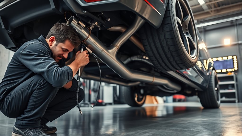
Complete the first leak check while the system is cool. Use a smoke machine or a regulated low-pressure test method intended for exhaust work. Do not connect full shop-line pressure, completely seal a heated tube, or create enough pressure to damage sensors, mufflers, flex sections, or gaskets.
Apply a soap-and-water leak solution to cool joints while the test gas or smoke is present. Bubbles indicate escaping gas. Mark each leak before releasing the test pressure.
- Repair a welded leak by cleaning and rewelding the defect.
- Correct a leaking flange by checking flatness, gasket condition, alignment, and even bolt torque.
- Correct a leaking slip joint by checking overlap, roundness, clamp position, and the approved sealing method.
- Replace a damaged flex section rather than coating it with paste.
Run the Engine Safely
After the cool-system test passes, start the engine outdoors or in a workshop with an effective vehicle-exhaust extraction system. Keep the outlet away from doors, windows, occupied spaces, and ventilation intakes.
Carbon monoxide is colorless and odorless. The CDC warns that even a small exhaust leak can allow carbon monoxide to build up inside a vehicle. Review its carbon-monoxide safety guidance.
Warning: Never run the vehicle in an attached garage for exhaust testing, even with the garage door open. Do not place your hands on or near hot exhaust parts while looking for a leak.
At idle, listen for ticking, hissing, rattling, and contact with heat shields or the body. Watch for movement at flex joints and hangers. Stop the engine if you smell exhaust inside the cabin or see a component contacting a fuel, brake, electrical, or body part.
Complete a First Heat Cycle
Allow the system to reach normal temperature in a controlled setting, then shut the vehicle off and let it cool completely. Recheck:
- Flange and clamp tightness
- Hanger alignment
- Flex-section position
- Axle, body, bumper, and driveshaft clearance
- Wiring and sensor clearance
- New soot marks or leaks
- Tailpipe movement and exit position
Use an appropriate scan tool to check for oxygen-sensor, catalyst-efficiency, temperature-sensor, or exhaust-pressure faults. A warning light after fabrication should be diagnosed rather than erased and ignored.
Verify Sound, Emissions, and Road Compliance
Check the rules that apply where the vehicle is registered and driven. Noise limits, emissions inspections, catalyst requirements, tailpipe placement, and modification rules vary by country, state, province, and municipality.
In the United States, the EPA states that removing a catalytic converter without an approved replacement can constitute illegal tampering. See the EPA transportation and emissions FAQ.
Track-only labeling does not automatically make prohibited road-vehicle modifications lawful. When the legal status is unclear, have the design reviewed by a qualified exhaust shop, inspection station, emissions specialist, or local authority before regular road use.
Warning: Do not delete, bypass, hollow out, or move required catalytic converters, particulate filters, oxygen sensors, or other emissions controls in a way that defeats their operation. Keep the finished sound level and tailpipe position within the rules that apply to the vehicle.
Troubleshooting Custom Exhaust Problems
Ticking Near a Joint
A ticking sound that becomes more noticeable under throttle often indicates a flange, gasket, slip-joint, or weld leak. Let the system cool, then inspect for soot marks and repeat the cool-system leak test.
Do not keep tightening a distorted flange. Check whether the faces are flat, the gasket matches, and the bolts are tightening evenly.
Rattling or Knocking
Inspect clearance at the axle, crossmembers, heat shields, driveshaft, bumper, body, and suspension. Check both cold and after a completed heat cycle because the system changes length and position as it warms.
A polished contact mark often identifies the problem. Correct the pipe or hanger position rather than packing material between the exhaust and the body.
Cruising-Speed Drone
Drone depends on engine speed, load, cabin structure, pipe length, and muffler or resonator design. Moving or adding a resonator may help, but the correct change depends on the frequency and available space.
Record the engine speed and road condition where the drone occurs before changing parts. This gives an exhaust specialist useful information for choosing a resonator or altering the layout.
Cracked Weld or Hanger
A crack often points to movement, poor penetration, contamination, excessive heat, or a system installed under tension. Repair the crack only after finding and correcting the cause.
Inspect nearby hangers and flex sections. A new weld may crack again if engine movement or exhaust weight continues to load the same joint.
Exhaust Sits Too Low
Adjust the routing or hanger geometry while preserving clearance from the body and suspension. Do not press the exhaust against the floor to gain ground clearance. Contact transfers vibration and heat into the body and may crack a joint.
Sensor or Catalyst Fault After Fabrication
Check for leaks before the sensor, incorrect sensor orientation, damaged wiring, connectors left loose, excessive sealant, moved catalysts, or sensors installed in the wrong pre- or post-catalyst position.
Read the diagnostic code and live data before replacing a sensor. A leak or placement error can create a misleading sensor reading.
Maintenance After Welding a Custom Exhaust
Inspect the exhaust after the first few drives and again after several full heat cycles. Let it cool before touching hardware or tubing.
Check every flange, clamp, weld, hanger, rubber isolator, flex section, sensor wire, and tailpipe. Look for soot, fresh scrape marks, loose hardware, heat damage, cracked mounts, or contact with surrounding parts.
Retighten service hardware only to the specified torque. Repeatedly overtightening a flange can bend it or crush the gasket.
Clean road salt, mud, oil, and track debris from accessible areas. Replace damaged gaskets, clamps, isolators, and flex sections before they overload nearby welds.
Repack a repackable silencer according to its manufacturer’s instructions when the sound becomes noticeably sharper or louder. Do not assume every increase in noise comes from packing; inspect for leaks first.
After all welding is complete, inspect the work area and vehicle for smoldering insulation, undercoating, debris, or heat damage. Continue the fire watch for the period required by your workplace procedure and local hot-work rules.
Frequently Asked Questions
Is 304 or 316 better for an exhaust?
304 or 304L is a common all-around choice for custom exhausts because it offers good corrosion resistance, availability, and weldability. 316 or 316L adds corrosion resistance in harsh chloride or chemical environments, but its extra cost does not automatically improve ordinary road performance. Confirm the alloy before selecting filler metal.
Do you need to back-purge a stainless exhaust?
Back purging is strongly recommended for TIG-welded stainless exhaust tubing. Argon protects the inside of the weld from heavy oxidation and helps preserve a smoother, more corrosion-resistant root. The purge setup must include a free vent so pressure cannot build inside the tube.
What welding process is best for exhaust tubing?
TIG welding is often preferred for thin stainless or titanium tubing because it provides precise heat and puddle control. MIG welding can also produce a reliable mild-steel or stainless exhaust when the wire, shielding gas, polarity, transfer mode, fit-up, and settings match the material.
What kind of TIG filler rod should I use?
Match the filler to the identified tubing alloy and joint. ER308L is commonly used with 304 or 304L stainless, while ER316L is commonly used with 316 or 316L. Dissimilar metals may need another filler, so check the filler manufacturer’s compatibility data before welding.
Is it illegal to weld or replace a muffler?
Welding or replacing a muffler is not automatically illegal. The completed system must still meet the emissions, sound, safety, inspection, and tailpipe rules that apply where the vehicle is driven. Do not remove or defeat required catalytic converters, filters, sensors, or other emissions controls.
Can you weld an exhaust while it is still on the car?
Some joints can be tack welded on the vehicle, but final welding is usually safer and easier after the section is removed. Before any on-car welding, follow the vehicle maker’s battery, restraint-system, electronic-module, and high-voltage isolation instructions. Shield fuel lines, wiring, rubber, coatings, and other nearby parts from heat and sparks.
Why does my custom exhaust rattle after welding?
The pipe may be touching the body, axle, heat shield, bumper, crossmember, or hanger hardware. The system may also be installed under tension. Check it when cold and after a complete heat cycle, then correct the pipe or hanger position before repeated contact cracks a weld.
Can exhaust paste repair a leaking weld?
Exhaust paste is not a proper permanent repair for a defective welded seam. Expose and clean the pinhole or crack, correct the fit or support problem, and reweld it. Use assembly paste only on compatible slip joints when the connector or sealant manufacturer allows it.
Conclusion
A reliable custom exhaust begins with accurate planning and fit-up, not with the final weld bead. Measure the actual vehicle, keep the joints square, protect the electronics, back-purge stainless tubing, and support the system without forcing it into position.
After welding, test the cool system for leaks, complete a controlled heat cycle, and inspect every flange, hanger, flex section, sensor, and clearance point. Keep required emissions equipment in place and confirm the rules that apply where the vehicle is driven. These checks help the exhaust stay quiet, serviceable, safe, and resistant to cracks or fumes entering the cabin.
Sources
- Miller: How to Weld Stainless Steel Tube and Pipe — backs up stainless preparation, filler-metal selection, heat control, argon shielding, and back purging.
- OSHA: Controlling Hazardous Fume and Gases During Welding — backs up welding-fume, ventilation, and hexavalent-chromium precautions.
- I-CAR: Battery and Electronic-System Welding Precautions — backs up battery isolation, work-clamp placement, cable routing, and vehicle-maker procedure requirements.
- US EPA: Transportation and Air-Pollution FAQ — backs up US catalytic-converter and emissions-tampering guidance.
- Walker Exhaust: Installation Tips — backs up thermal growth, neutral hanger alignment, slip-fit assembly, and even flange tightening.
- CDC: Carbon Monoxide Poisoning Basics — backs up exhaust-leak and enclosed-garage safety guidance.