
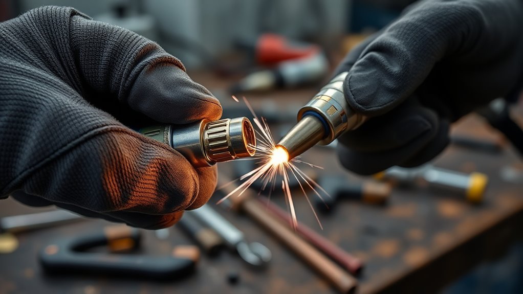
Replacing a MIG tip is a quick maintenance job, but the small copper part has a major effect on wire feeding, current transfer, arc stability, spatter, and bead quality. For a reliable repair, use a contact tip that fits both your wire and MIG gun, install it without damaging the threads, refit the correct nozzle, and confirm the wire extension before welding again.
Quick Answer
To replace a MIG contact tip, let the gun cool, switch the welder off, and isolate power as directed by the manual. Remove the nozzle, unscrew the old tip, install a compatible tip for the wire and gun, refit the nozzle, set the correct wire extension, and test the setup on scrap.
Key Takeaways
- For common steel MIG wire, match the contact-tip marking to the wire diameter, such as a .030 tip for .030 steel wire.
- Aluminum wire often needs an aluminum-specific tip with a larger bore, so follow the gun or wire manufacturer’s consumable chart.
- Replace a tip when its bore becomes enlarged, oval, blocked, fused, or unable to feed wire smoothly.
- Turn the welder off, isolate input power according to its manual, and let the gun cool before touching the front end.
- The nozzle, diffuser, and contact tip perform different jobs and must all be compatible with the gun.
- A 3/8- to 1/2-inch wire extension is a common starting range for many short-circuit steel MIG setups, but the manufacturer’s procedure takes priority.
At a Glance
| Time Required | 5 to 10 minutes |
| Difficulty | Easy beginner maintenance |
| Tools Needed | Compatible contact tip, MIG pliers or the specified wrench, side cutters, clean rag, gloves, and safety glasses |
| Cost | Low: one compatible replacement contact tip |
Warning: A MIG nozzle and contact tip can remain hot after welding, and gun components may be electrically energized while the machine is on. Point the gun in a safe direction, switch the welder off, isolate input power according to the manufacturer’s maintenance instructions, and wait for the front end to cool. Wear gloves and safety glasses. When welding resumes, use suitable ventilation and keep your head outside the fume plume. Review OSHA’s welding hazard guidance before working in a shop or workplace.
Know the Parts at the Front of a MIG Gun
The term MIG tip normally means the contact tip, but it is only one part of the gun’s front end. Knowing which part does what helps you buy the correct replacement and prevents damage during removal.
| Part | Main Job |
|---|---|
| Contact tip | Guides the welding wire and transfers welding current to it. |
| Gas diffuser or tip adapter | Supports the contact tip and distributes shielding gas on gas-shielded setups. |
| Nozzle | Surrounds the tip and directs shielding gas around the arc, or protects the front end on some self-shielded flux-core setups. |
Contact tips that look similar can have different threads, lengths, tapers, and seating designs. Confirm the gun make or series before ordering replacements rather than choosing a tip by appearance alone.
When to Replace a MIG Tip
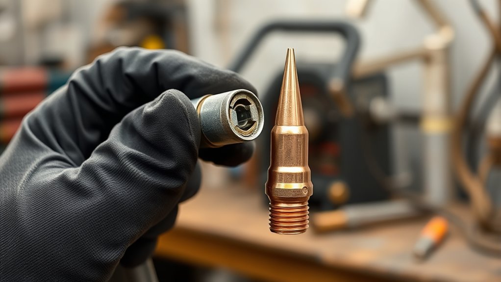
Replace a MIG contact tip when you see melted wire buildup, a blocked opening, a visibly enlarged or oval bore, damaged threads, or a wire end fused into the tip. Lincoln Electric’s official MIG PAK HD operator’s manual specifically recommends replacement when the tip hole becomes enlarged or elongated.
You should also inspect the tip when the arc sounds rough, the wire pulses or stubs into the work, spatter increases suddenly, or the bead becomes uneven even though the voltage and wire-feed settings have not changed.
The tip wears because welding current passes from the copper tip into wire that is continuously sliding through its bore. Heat, dirt, spatter, wire cast, and feed resistance gradually wear or contaminate that bore. Poor contact can then cause an erratic arc, while excessive drag can contribute to feeding trouble or burnback.
Remove light external spatter before replacing the tip. If the wire still does not pass smoothly, the bore is visibly distorted, or burnback has damaged the tip, replacement is usually more reliable than aggressive cleaning.
Note: A damaged contact tip is not the only cause of burnback. Incorrect wire speed, excessive voltage, an inconsistent gun distance, a restricted liner, incorrect drive-roll tension, or poor work-clamp contact can create similar symptoms.
Match the Contact Tip to the Wire and Gun
For common steel MIG wire, match the nominal contact-tip size to the wire diameter. Use a .023 or .025 tip with the steel-wire size listed for that tip, a .030 tip with .030 steel wire, and a .035 tip with .035 steel wire. Check the spool label and tip marking instead of assuming that the old tip was correct.
If a steel-wire tip is too tight, the wire may scrape, chatter, overheat, or bind. If it is too loose, current transfer and wire placement may become less consistent. Either condition can increase spatter and make the arc harder to control.
Products Worth Considering

Package list: 30 pieces of 0.030 inch mig welder tips.

1. Package Includes 30 Premium Quality .023” (Ø0.6mm)welding Tips.

20Pcs Contact Tip .023'' Ø0.6mm
Aluminum Wire Needs Special Attention
Do not apply the steel-wire sizing rule blindly to aluminum. Aluminum expands more as it heats and is more likely to bind in a tight bore. Hobart Brothers recommends aluminum contact-tip bores approximately 10% larger than the electrode and warns that 3/64-inch aluminum wire is not the same size as .045-inch steel wire. Review its aluminum contact-tip guidance and use the consumable specified for your spool gun or push-pull gun.
Some manufacturers mark an aluminum-specific contact tip by the wire size it is designed to run even though its actual bore is larger. For that reason, follow the part number and application chart rather than measuring only the stamped number.
Contact Tip Compatibility Checklist
Before installing the replacement, confirm all of these details:
- Wire diameter: Match the steel wire directly or use the specified aluminum-tip bore.
- Wire material: Steel, stainless steel, flux-cored wire, and aluminum may use different consumables.
- Gun make or series: Tips from different gun platforms can use different threads and lengths.
- Tip style: Confirm whether the gun requires a standard, tapered, heavy-duty, or extended-life tip.
- Thread and seating surface: The replacement must start smoothly and seat fully without forcing it.
- Tip position: Use the recess, flush, or extended position recommended for the gun and process.
Proper Fit Check
Clip off a balled, bent, rusty, or contaminated wire end before passing it through a new tip. The wire should move through without heavy drag, scraping, or binding. Some controlled clearance is normal, so do not judge fit by expecting the wire to feel clamped tightly inside the bore.
If the correct tip still produces heavy resistance, inspect the liner, drive rolls, spool brake or hub tension, cable bends, inlet guide, and wire condition. A kinked or rusty wire can damage a new tip quickly.
Tools and Parts You Need
You only need a few items, but the new tip must be compatible with the gun as well as the wire.
- Compatible contact tip: Match the wire, material, gun series, thread, length, and tip style.
- MIG pliers or specified wrench: Use the correct tool to loosen and snug the tip without crushing nearby parts.
- Side cutters: Cut away a balled, bent, rusty, or fused wire end.
- Clean rag: Remove loose dirt and spatter from the nozzle area.
- Gloves and safety glasses: Protect your hands and eyes while handling wire and hot consumables.
- Gun manual or consumable chart: Confirm part compatibility, tip position, and shutdown instructions.
Pro Tip: Store spare tips in separate, labeled containers by gun series and wire size. Tips with different bores can look almost identical when you are working quickly.
Products Worth Considering
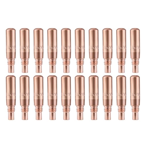
Package Including Pack of 20 Premium Quality Contact Tips .035" (0.9mm).

Premium quality Lincoln/Tweco style standard 11-35 (0.035") contact tips for 100L and Mini MIG guns

1.Non-Stick Coating Reduces Slag Buildup – Our special anti-spatter coating prevents slag from sticking to the tips, keeping your weld area clean and reducing downtime.
Turn Off the Welder and Prepare the Wire
Point the gun away from yourself and other people. Let the nozzle, tip, and gun neck cool fully. Switch the welder off, then unplug it or follow the manufacturer’s specified isolation or lockout procedure before servicing the gun.
Put on gloves and safety glasses. Clip off any melted, balled, rusty, or bent wire end. A straight, clean end is less likely to scrape the bore or catch as it passes through the replacement contact tip.
Keep the gun cable as straight as practical while you work. A tight loop or sharp bend adds feed resistance and can make a liner problem look like a contact-tip problem.
A new tip cannot correct a rusty wire, damaged liner, incorrect drive roll, or sharply bent gun cable.
Remove the Nozzle and Old Tip
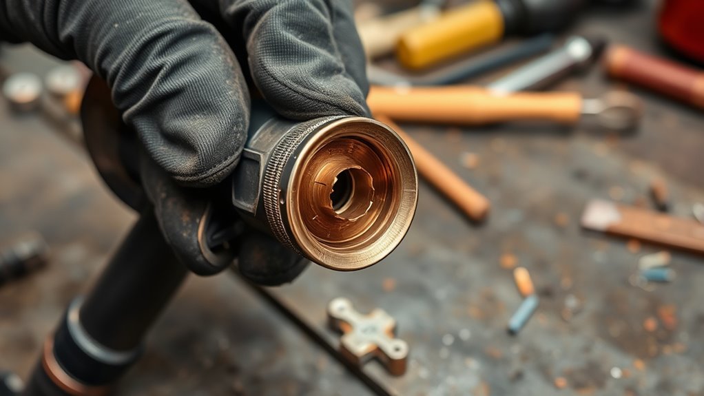
Most MIG nozzles either pull off, twist off, or unscrew, depending on the gun. Hold the gun neck securely and remove the nozzle using the method specified for that model. If spatter has made it tight, work it loose gently with MIG pliers without crushing or distorting it.
With the nozzle removed, place the correct wrench or MIG pliers squarely on the contact tip. Turn the tip counterclockwise while keeping the tool aligned with the tip. Avoid side-loading the diffuser or bending the gun neck.
| Step | Action |
|---|---|
| 1 | Let the gun cool and isolate power according to the manual. |
| 2 | Cut away the damaged or contaminated wire end. |
| 3 | Pull, twist, or unscrew the nozzle as required by the gun. |
| 4 | Unscrew the old contact tip counterclockwise. |
| 5 | Inspect the diffuser threads, insulator, nozzle, and wire before reassembly. |
Remove a Tip With Wire Burned Back Into It
If the wire has fused inside the contact tip, do not keep pulling the trigger. Isolate power, remove the nozzle, and cut the wire behind the fused area if you can reach it safely. Unscrew the tip with the trapped wire still inside, then pull the damaged section of wire out after the tip has been removed.
If the tip will not loosen, use steady pressure with the correct tool. Do not heat the tip, hammer the gun neck, or twist hard enough to bend it. A tip that has seized because of damaged or galled threads may require replacement of the diffuser or tip adapter.
Note: Stop if the diffuser turns with the tip, the threads crumble, or the gun neck begins to flex. Replacing a damaged diffuser is safer and more reliable than forcing a new tip into bad threads.
Install the New MIG Contact Tip
Compare the new tip with the old one before installation. Confirm its part number, thread, length, and bore marking. Do not install it merely because it can be started in the diffuser.
Guide the straight wire through the new tip, then start the contact tip by hand. It should turn smoothly for several threads. If it binds immediately or sits at an angle, back it out and inspect both sets of threads for dirt, damage, or cross-threading.
Once the tip seats fully, snug it with the specified wrench or MIG pliers. It must be secure enough to maintain good electrical and thermal contact, but it should not be crushed or overtightened. Lincoln’s replacement procedure specifically warns against overtightening.
Clip the wire end cleanly if needed. Reinstall the nozzle and make sure it seats correctly without touching or shorting against the contact tip.
Choose the Right Nozzle
The nozzle affects shielding-gas coverage, joint access, visibility, and spatter buildup. Select it for the gun, process, amperage range, and joint rather than using wire diameter as the only guide.
Solid-Wire MIG Nozzle
Solid-wire GMAW or MIG uses externally supplied shielding gas. The nozzle directs that gas around the arc and weld pool to reduce atmospheric contamination. OSHA describes GMAW as a consumable-electrode process with an external gas shield in its welding-fume fact sheet.
Replace a gas nozzle if it is cracked, badly distorted, loose, or so heavily clogged that it restricts gas flow. Clean moderate spatter without gouging or deforming the nozzle.
Self-Shielded Flux-Core Nozzle
Self-shielded flux-cored wire creates shielding from ingredients inside the wire and does not require an external shielding-gas bottle. Many guns can use a smaller flux-core nozzle that improves joint visibility while protecting the diffuser and threads from spatter.
Do not assume that the same nozzle position is best for solid-wire MIG and self-shielded flux-core. Confirm the recommended consumables, polarity, and wire extension for the exact wire.
Gas-Shielded Flux-Core Nozzle
Gas-shielded flux-cored wire does require external shielding gas. It therefore needs a gas nozzle that provides the specified coverage and fits the gun correctly.
Check the wire classification, data sheet, and machine setup chart before changing the nozzle, gas, polarity, or wire extension. The wrong process setup can cause porosity, excessive spatter, poor fusion, and unstable feeding.
Set the Tip Position and Wire Stickout
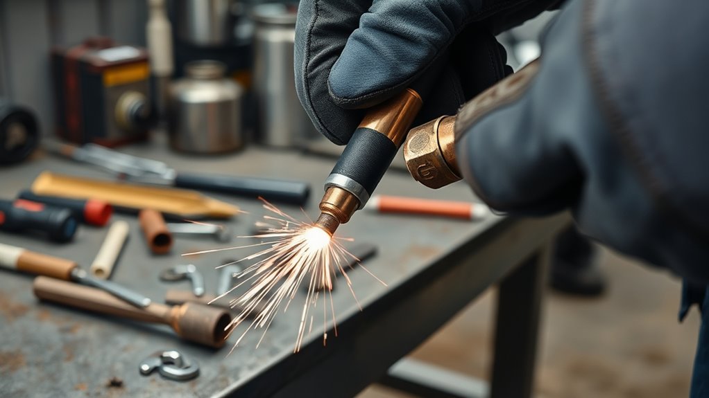
Two measurements are easy to confuse. Tip position describes whether the contact tip is recessed inside the nozzle, flush with it, or extended past it. Wire stickout, also called electrode extension, is the distance from the end of the contact tip to the end of the unmelted wire.
Contact-tip-to-work distance, or CTWD, is measured from the end of the contact tip to the workpiece while welding. CTWD includes the wire extension plus the arc length, so it is not exactly the same measurement as stickout.
For many small short-circuit steel MIG setups, a wire extension around 3/8 to 1/2 inch is a useful starting range. Lincoln’s MIG PAK HD manual uses approximately 3/8 to 1/2 inch for its GMAW setup. Your machine chart, welding procedure, or wire manufacturer’s recommendation should take priority.
Too much extension can increase wire resistance heating, reduce effective welding current, make the arc less stable, and weaken gas coverage. Too little extension can increase nozzle spatter and the chance of the wire burning back into the tip.
Self-shielded flux-cored wires commonly use a longer extension than short-circuit solid-wire MIG, while spray, pulsed, aluminum, and higher-current procedures may use different tip positions and CTWD values. Do not carry one distance over to every wire and process.
Check Wire Feed and Weld Quality
After reassembly, restore power according to the machine manual. Point the gun in a safe direction and briefly check that the wire advances smoothly. If the wire jerks, slips, or stops, shut the machine down again before investigating the liner, rolls, spool tension, or tip fit.
For gas-shielded welding, confirm that shielding gas reaches the nozzle and that the nozzle is not blocked. Then run a short test bead on clean scrap of similar material and thickness.
Listen for a steady arc and watch the wire feed. The bead should be reasonably even for the chosen settings, without sudden stubbing, heavy porosity, or a sharp increase in spatter. Do not use appearance alone to approve a structural weld; follow the applicable welding procedure and inspection requirements.
| Check | Good Sign | Problem Sign |
|---|---|---|
| Wire feed | Steady movement | Pulsing, slipping, stubbing, or bird-nesting |
| Arc | Stable for the selected process | Repeated popping, stubbing, or burnback |
| Bead | Consistent for the procedure | Porosity, severe spatter, undercut, or irregular width |
| Contact tip | Secure with an open, round bore | Loose, blackened, melted, oval, or blocked |
| Nozzle | Open, seated, and undamaged | Blocked, cracked, loose, shorted, or bent |
Troubleshooting After a New Contact Tip
If a new contact tip does not solve the problem, stop replacing tips and inspect the rest of the wire-feed and welding circuit.
- Wire burns back again: Check wire-feed speed, voltage, stickout, tip bore, liner restriction, drive-roll slip, and work-clamp contact.
- Wire feed remains jerky: Straighten the cable and inspect the liner, inlet guide, drive-roll groove, drive pressure, spool brake, and wire surface.
- Bird-nesting occurs: Look for a blocked tip, restricted liner, incorrect roll groove, excessive drive pressure, or soft wire being pushed through an unsuitable gun setup.
- Porosity appears: Check the gas cylinder, regulator, hose, diffuser, nozzle blockage, drafts, base-metal contamination, and required gas flow.
- Heavy spatter returns: Confirm polarity, voltage, wire speed, gun angle, extension, gas selection, and base-metal cleanliness.
- The new tip becomes unusually hot: Shut down and check whether it is loose, cross-threaded, the wrong style, or making poor contact with the diffuser.
- The wire wanders at the arc: Confirm the correct tip bore, tip condition, wire cast, liner alignment, and gun-neck condition.
How to Make MIG Tips Last Longer
Keep the nozzle and tip free from heavy spatter, maintain the recommended wire extension, and avoid dipping the wire or front end into the weld pool. Clean rust, paint, oil, and other contamination from the weld area whenever the procedure requires clean metal.
Use only enough drive-roll pressure to feed the wire reliably. Excess pressure can deform some wires and increase friction through the liner and contact tip. Keep the cable as straight as practical and use the correct drive-roll groove for the wire.
Store wire in a dry place and replace rusty or contaminated wire rather than feeding it through the gun. Wire contamination can clog the liner and wear the tip bore.
Inspect the nozzle, tip, diffuser, insulator, liner, and work clamp before each welding session. Occasional users can replace tips when wear symptoms appear. Production shops should base preventive replacement intervals on amperage, wire type, arc time, and the cost of unplanned downtime rather than using one schedule for every application.
Frequently Asked Questions
How do you replace a MIG welder contact tip?
Let the gun cool, switch the welder off, isolate power according to its manual, remove the nozzle, and unscrew the old tip. Install a compatible replacement by hand, snug it without overtightening, refit the nozzle, set the correct wire extension, and test the setup on scrap.
How do I know what contact tip size to use?
For common steel MIG wire, match the nominal tip size to the wire diameter, such as a .030 tip for .030 wire. Also confirm the gun series, thread, tip length, and style. Aluminum wire usually needs an aluminum-specific tip with a larger bore specified by the manufacturer.
When should you replace a MIG contact tip?
Replace it when the bore becomes enlarged or oval, the wire binds, burnback fuses wire into the tip, the threads are damaged, or the arc remains unstable after light cleaning and basic setup checks.
Can you clean and reuse a MIG contact tip?
You can remove light external spatter if the bore remains round and the wire still feeds smoothly. Replace the tip if its bore is enlarged, deeply scored, blocked, fused, or distorted. Avoid drilling the bore larger because that changes the fit and current-transfer behavior.
Can I use the same nozzle for MIG and flux-core?
The parts may physically fit, but the best nozzle depends on the process. Solid-wire MIG and gas-shielded flux-core need suitable shielding-gas coverage. Self-shielded flux-core does not use external gas and often uses a smaller protective nozzle for visibility and diffuser protection.
What is the best stickout after replacing a MIG tip?
For many short-circuit steel MIG setups, 3/8 to 1/2 inch from the contact-tip end to the wire end is a useful starting range. Use the machine chart, wire data sheet, or welding procedure when it gives a different value. Flux-cored, aluminum, spray, and pulsed procedures can require different extensions.
Why does a new contact tip burn back immediately?
Immediate repeat burnback can come from low wire-feed speed, excessive voltage, a tip bore that is too tight, liner restriction, drive-roll slip, excessive or inconsistent gun distance, or poor work-clamp contact. Correct the underlying cause before installing another tip.
Does the welder brand matter when replacing a MIG tip?
Yes. The nominal wire size is only one requirement. The replacement tip must also match the MIG gun’s thread, length, seating design, and intended position. Buy the part listed for the gun series or a replacement confirmed as compatible by the manufacturer.
Conclusion
Replacing a MIG contact tip is straightforward when you treat it as part of the complete wire-feed system. Isolate power, remove the nozzle and worn tip, confirm the replacement’s wire and gun compatibility, install it without cross-threading or overtightening, and restore the correct nozzle and wire extension. Finish with a controlled feed check and a test bead. If the same fault returns, inspect the liner, drive rolls, settings, gas system, and work connection instead of sacrificing another new tip.
Sources
- OSHA Welding, Cutting, and Brazing: Hazards and Solutions — welding burns, electrical hazards, fumes, radiation, and protective practices.
- OSHA Fact Sheet: Controlling Hazardous Fume and Gases During Welding — MIG shielding, fume exposure, ventilation, and respiratory protection.
- Lincoln Electric MIG PAK HD Operator’s Manual — contact-tip replacement, wear indicators, wire sizing, maintenance, and wire-extension guidance.
- Hobart Brothers Aluminum Welding Guide: Contact Tips and Maintenance — aluminum contact-tip bore sizing and consumable selection.




