When I first started using a Lincoln welder, I expected the settings to be simple: choose the metal thickness, turn two knobs, and start welding. In practice, voltage, wire-feed speed, amperage, polarity, shielding gas, filler metal, joint design, and travel speed all work together. A setting that produces a clean bead on one joint can cause burn-through, cold lap, or porosity on another.
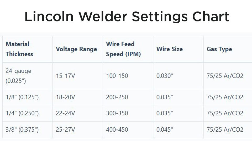
A Lincoln welder settings chart gives you a starting point, not a universal recipe. The chart inside your machine, the operator manual for its exact code number, and the data sheet for your wire or electrode should always take priority over a generic table.
This guide explains how to find those settings, how to adjust them safely, and how to troubleshoot MIG, flux-core, TIG, and stick welds without changing several controls at once.
Quick Answer
Start with the chart inside your Lincoln welder or the operator manual for its exact model and code number. Match the process, metal, thickness, wire or electrode, gas, and polarity. Run a test bead on matching scrap, inspect the bead, and adjust voltage, wire speed, or amperage one small step at a time.
Key Takeaways
- The machine-door chart and model-specific operator manual override generic settings.
- MIG voltage and wire-feed speed must be balanced; TIG and stick settings center on amperage and correct polarity.
- Solid MIG wire, self-shielded flux-core, gas-shielded flux-core, TIG, and stick may require different polarities.
- Stainless and aluminum require alloy-compatible filler metals and process-specific shielding gas.
- Test every setup on matching scrap before welding the finished part or any code-regulated joint.
At a Glance
| Time Required | About 10–20 minutes to identify the correct chart, load the consumable, set the machine, and run test beads |
| Difficulty | Beginner to intermediate; critical and code-regulated welds require qualified procedures and personnel |
| Tools Needed | Operator manual, machine chart, matching scrap, measuring tool, correct wire or electrode, shielding gas when required, cleaning tools, work clamp, and welding PPE |
| Cost | Usually no extra cost beyond normal consumables, gas, scrap, and required safety equipment |
Warning: Welding can cause electrical shock, fire, burns, eye and skin injury, and hazardous fume exposure. Remove combustible materials, secure gas cylinders, use suitable ventilation and PPE, and never weld on an unknown container or coated metal until the hazards have been identified and controlled. Generic settings do not qualify a weld for structural, pressure, vehicle-safety, or other code-regulated service.
Why Getting Your Lincoln Welder Settings Right Matters
Your settings control more than bead appearance. They influence fusion, penetration, bead profile, spatter, heat input, distortion, electrode behavior, and the amount of filler metal deposited into the joint.
With MIG welding, voltage mainly affects arc length and bead shape, while wire-feed speed has a strong effect on welding current. With TIG and stick welding, amperage is the main heat control, but polarity, electrode diameter, arc length, travel speed, and joint fit-up still matter.
Too much heat can cause burn-through, undercut, excessive distortion, or an oversized weld pool. Too little heat can leave a tall, narrow bead with poor toe fusion or incomplete penetration. Incorrect polarity may make the arc unstable, overheat the tungsten, or prevent a flux-core wire from performing as designed.
A settings chart gets the arc started. A cleaned joint, matching test coupon, and careful bead inspection tell you whether the complete setup is right.
Find the Correct Lincoln Settings Chart First
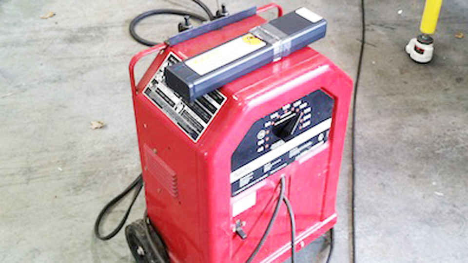
Before using any online chart, identify the exact machine. Lincoln welders with similar names may have different input power, output ranges, controls, drive systems, and duty cycles.
- Find the product name and code number. Look on the rating plate, rear panel, case, or documentation. The code number helps identify the correct revision.
- Check the machine chart. Many wire-feed welders have an application chart inside the wire-drive door.
- Open the exact operator manual. Use Lincoln Electric’s operator-manual search.
- Identify the process. Confirm whether you are using solid-wire MIG, self-shielded flux-core, gas-shielded flux-core, TIG, or stick.
- Match the consumable. Record the wire or electrode classification, brand, diameter, required polarity, and shielding gas.
- Measure the actual metal. Do not estimate sheet gauge by appearance, especially after grinding or corrosion.
- Choose the joint and position. A lap joint, fillet, open root, butt joint, vertical weld, and overhead weld may need different technique or settings.
Pro Tip: Photograph the settings chart inside the wire compartment and save the operator manual on your phone. Record successful settings beside the metal thickness, joint type, wire, gas, position, and travel technique instead of saving only the knob numbers.
Note: The numerical tables below are practical starting windows. They are not a replacement for your machine chart, consumable data sheet, welding procedure specification, or test results.
Popular Lincoln Welder Models and What They Offer
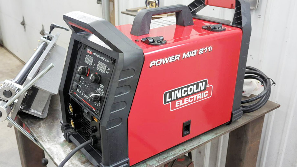
The correct settings depend partly on what your machine can produce. These three Lincoln models show why one chart cannot cover every welder.
| Model | Processes | Published Output Information | Best Fit |
|---|---|---|---|
| POWER MIG 140 MP | MIG, flux-core, DC TIG, and stick | MIG 30–140 A, DC TIG 10–120 A, stick 25–90 A, and wire feed from 40–500 IPM | Portable 120-volt home, maintenance, and light-fabrication work within the machine’s capacity |
| POWER MIG 256 | MIG and flux-core | 30–300 A output, wire feed from 50–700 IPM, and a published rating of 250 A at 26 V with a 40% duty cycle | Higher-output fabrication and shop work |
| Precision TIG 225 | AC/DC TIG and stick | 5–230 A AC or DC output, AC balance control, and pulse capability | Precision steel, stainless, and aluminum TIG work |
Model options and accessories also matter. For example, feeding soft aluminum wire through a conventional MIG gun can be difficult. The POWER MIG 140 MP lists an optional spool gun for aluminum work. Always confirm that the gun, drive rolls, liner, contact tip, and machine output suit the selected wire.
Products Worth Considering
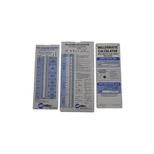
Comprehensive 3‑in‑1 reference pack covers MIG, TIG and Stick welding parameters—ideal for welders who work across multiple processes
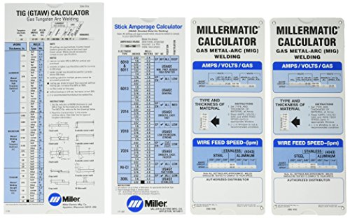
Miller electric 043125 Package, Miller Calculator pack
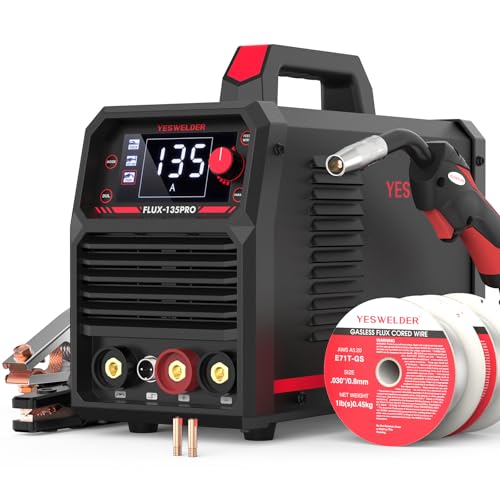
READY OUT OF THE BOX: Start welding immediately! It masterfully handles Gasless Flux Core MIG, Stick, and Lift TIG (Extra Lift TIG torch required). This budget-friendly 3-in-1 machine includes extra E71T-GS .030''&.035'' flux core wires, known for its smooth arc and high feedability. Say goodbye to heavy shielding gas cylinders—perfect for outdoor, windy, or all-position welding.
Lincoln Welder Polarity Chart
Polarity is one of the first items to verify after changing processes or consumables. Do not assume that every wire called “flux-core” uses the same connection.
| Process | Common Polarity | Important Note |
|---|---|---|
| Solid-wire MIG/GMAW | DCEP, electrode positive | Confirm the wire and machine chart. Shielding gas is required. |
| Self-shielded flux-core/FCAW-S | Often DCEN, electrode negative | Not universal. Lincoln NR-211-MP uses DCEN; follow the exact wire data. |
| Gas-shielded flux-core/FCAW-G | Often DCEP | Use the polarity and gas specified by the wire manufacturer. |
| TIG on mild or stainless steel | DCEN, torch electrode negative | DCEP can overheat the tungsten and is not the normal setup. |
| TIG on aluminum or magnesium | AC | AC provides oxide-cleaning action during the electrode-positive portion and penetration during the electrode-negative portion. |
| Stick/SMAW | Electrode-specific | Some rods are DCEP only; others can run on DCEP, DCEN, or AC. |
Products Worth Considering

🧲 Sticks to Toolboxes & Welders – Heavy-duty magnetic welding chart adheres to metal surfaces like your welding table, toolbox, or wall for instant reference while working.

Richard Finch, Welder's Handbook: A Complete Guide to MIG, TIG, Arc & Oxyacetylene Welding, "Completely Revised and Updated Edition!" paperback
MIG Welding With Lincoln: Basics and Beyond
MIG welding, also called GMAW, uses a continuously fed wire electrode and external shielding gas. It is productive, relatively easy to learn, and useful for automotive panels, brackets, gates, general fabrication, and many repair jobs.
Clean metal is still essential. Rust, oil, paint, mill scale, moisture, zinc coating, and poor electrical contact can destabilize the arc or contaminate the weld. Clean the joint and the work-clamp location to sound metal before setting the machine.
Voltage and Wire-Feed Speed: Decoding the Chart
Voltage changes arc length and bead profile. Wire-feed speed, measured in inches per minute, controls how quickly the wire enters the arc and strongly influences welding current on a constant-voltage MIG machine.
The following ranges are conservative starting windows for common solid-wire mild-steel work. Your Lincoln chart may specify different values because machine calibration, wire type, shielding gas, joint design, position, and transfer mode all affect the result.
| Material Thickness | Suggested Wire | Voltage | Wire Feed | Gas and Polarity | Setup Note |
|---|---|---|---|---|---|
| 24 gauge, about 0.025 in. | 0.025 in. ER70S-6 | About 14.5–16.5 V | About 100–160 IPM | 75/25 argon/CO₂, DCEP | Use a tight joint, short tacks, and cooling pauses to control burn-through. |
| 18 gauge, about 0.048 in. | 0.025 or 0.030 in. ER70S-6 | About 16–18 V | About 140–220 IPM | 75/25 argon/CO₂, DCEP | Use short-circuit transfer and avoid a long contact-tip-to-work distance. |
| 1/8 in. | 0.030 or 0.035 in. ER70S-6 | About 18–20.5 V | About 200–320 IPM | 75/25 argon/CO₂, DCEP | Joint design and machine output determine whether one pass is suitable. |
| 1/4 in. | 0.035 or 0.045 in. wire | About 21–25 V | About 300–450 IPM | Gas selected for the transfer mode, DCEP | Beveling, a root gap, or multiple passes may be required. |
| 3/8 in. | Often 0.045 in. wire | About 24–29 V | About 350–550 IPM | Manufacturer-specified gas, DCEP | Use a capable industrial machine and a qualified joint procedure when strength is critical. |
Lincoln’s SuperArc L-56 data sheet shows how wire diameter, feed speed, gas, current, and voltage interact. It also notes that settings may change when switching between carbon dioxide and an argon/CO₂ blend.
Gas Selection and Flow Rates
Shielding gas protects the molten weld pool from surrounding air. Too little flow, a leak, a blocked nozzle, contamination, or a strong draft can cause porosity. Excessive flow can create turbulence and pull air into the shielding stream.
| Application | Common Gas | Typical Starting Flow | Important Limitation |
|---|---|---|---|
| Mild-steel short-circuit MIG | 75% argon/25% CO₂ | About 20–30 CFH | Flow depends on nozzle size, joint access, and draft conditions. |
| Mild-steel MIG with carbon dioxide | 100% CO₂ | About 20–30 CFH | Expect different voltage behavior, penetration, and spatter than with 75/25 gas. |
| Stainless-steel MIG | Wire- and transfer-specific blend | Often about 20–35 CFH | Do not assume tri-mix is correct. Follow the stainless-wire data sheet. |
| Aluminum MIG | 100% argon | Often about 20–30 CFH | Use a suitable spool gun or push-pull system when required. |
| Self-shielded flux-core | No external gas | Not applicable | Use the wire’s specified polarity and remove slag between passes. |
| Gas-shielded flux-core | Wire-specific gas | Follow the data sheet | Do not substitute a MIG gas without checking the wire specification. |
If wind disturbs the shielding gas, stop and install a windbreak. Simply turning the regulator higher is not a dependable fix. For outdoor repairs, a suitable self-shielded flux-core or stick process may be more practical.
Step-by-Step MIG Setup on a Lincoln Welder
- Disconnect input power before opening the wire compartment.
- Confirm wire compatibility. Match the wire classification and diameter to the base metal, drive rolls, liner, contact tip, machine, and joint.
- Set the drive roll correctly. Use the proper groove and only enough pressure to feed reliably without crushing or deforming the wire.
- Set polarity. Solid ER70S-6 wire normally uses DCEP. Self-shielded wire may use DCEN, but the spool label and data sheet control.
- Connect the gas when required. Check the cylinder, regulator, hose, gun connection, diffuser, O-rings, and nozzle for leaks or blockage.
- Set voltage and wire speed. Start with the machine-door chart for the measured thickness and selected wire.
- Clean and clamp the test coupon. Use the same alloy, thickness, joint, orientation, and fit-up as the finished part.
- Set gun position. For many solid-wire welds, use a modest push angle of roughly 5–15 degrees. Keep the contact-tip-to-work distance near the value specified for the wire and transfer mode.
- Run a test bead. Hold a steady travel speed and watch the leading edge of the puddle.
- Change one setting at a time. Adjust in small steps, then repeat the test until the arc and bead are stable.
How to Read the MIG Arc
- Wire repeatedly stubs into the plate: Voltage may be too low for the selected wire-feed speed, or wire-feed speed may be too high. Increase voltage slightly or reduce wire feed in small steps.
- Arc sounds long and hissy: Voltage may be too high or wire-feed speed too low. Shorten the arc by reducing voltage or increasing feed slightly.
- Heavy spatter: Check polarity, gas, surface cleanliness, contact-tip-to-work distance, voltage-to-feed balance, and work-clamp contact.
- Burn-through: Reduce heat input, increase travel speed, shorten weld time, tighten the joint gap, or use smaller wire and a stitch-welding sequence.
- Cold lap or a tall rope-like bead: Increase heat within the machine’s capacity, slow slightly, correct the gun angle, and make sure the arc reaches both joint faces.
Flux-Core Settings on Lincoln Wire-Feed Welders
Flux-core wire is not simply “MIG without gas.” Self-shielded FCAW-S and gas-shielded FCAW-G use different wire designs, polarity requirements, gases, techniques, and applications.
Self-Shielded Flux-Core
Self-shielded wire carries flux ingredients that generate shielding and slag. It is useful outdoors because it does not rely on an external gas cloud, but wind limits and worksite controls still apply.
Lincoln NR-211-MP is a common example that uses DCEN. Other products may differ, so read the spool label and data sheet before moving the gun connections. Use the recommended contact-tip-to-work distance and usually a slight drag angle unless the product instructions specify another technique.
Gas-Shielded Flux-Core
Gas-shielded flux-core normally uses an external shielding gas and often runs on DCEP, but the wire data sheet determines the correct setup. These wires can deliver high deposition rates on thicker material, yet they still require slag removal between passes and careful control of joint preparation.
TIG Welding Settings on Lincoln Machines
TIG, or GTAW, uses a non-consumable tungsten electrode to create the arc. You add filler metal separately when the joint requires it. TIG offers precise heat control and clean bead appearance, making it useful for thin steel, stainless steel, aluminum, tubing, and detailed fabrication.
For normal TIG welding of mild steel and stainless steel, connect the torch for DCEN. For aluminum on an AC-capable machine, use AC and adjust balance according to the machine manual, oxide condition, tungsten, and joint.
TIG Amperage and Polarity Chart
The common “one amp per 0.001 inch” rule can provide a rough starting estimate for DC-TIG steel, but it is not universal. Aluminum conducts heat quickly, stainless responds differently from mild steel, and an outside-corner joint does not behave like a thick fillet or open root.
| Material | Thickness | Maximum Current Starting Range | Polarity | Argon Flow | Tungsten |
|---|---|---|---|---|---|
| Mild steel | 1/16 in. | About 45–75 A | DCEN | About 12–20 CFH | 1/16 in. |
| Mild steel | 1/8 in. | About 90–130 A | DCEN | About 15–20 CFH | 3/32 in. |
| Stainless steel | 1/16 in. | About 40–70 A | DCEN | About 12–20 CFH | 1/16 in. |
| Stainless steel | 1/8 in. | About 80–120 A | DCEN | About 15–20 CFH | 3/32 in. |
| Aluminum | 1/8 in. | About 100–150 A | AC | About 15–25 CFH | 3/32 in. |
| Aluminum | 1/4 in. | About 180–230 A | AC | About 20–30 CFH | 1/8 in. |
When using a foot pedal, the amperage control usually sets the available maximum. You then apply only the current needed to establish and move the puddle. Start lower on exposed edges, thin corners, and poorly supported sheet.
Pulse Settings and When to Use Them
Pulse TIG alternates between a peak current and a lower background current. It can reduce average heat input, help you establish a repeatable rhythm, and improve puddle control on thin, vertical, or position-sensitive joints.
At a low pulse rate, each pulse is easy to see and can guide filler timing. Higher pulse frequencies can tighten the arc and smooth the heat input on machines that support them. There is no universal best frequency, peak time, or background percentage. Begin with the manual’s default or recommended values, then test on matching scrap.
If pulse mode makes you travel too slowly or creates an irregular bead, turn it off and establish a stable conventional TIG technique first.
Preparing TIG Joints and Choosing Filler Rod
TIG is sensitive to contamination. Remove oil, paint, moisture, rust, oxide, and embedded grinding debris. Use dedicated stainless tools on stainless material, and use a dedicated stainless brush to remove aluminum oxide immediately before welding aluminum.
Match filler metal to the actual alloy and service requirements:
- Mild steel: ER70S-2 and ER70S-6 are common choices, but the joint and procedure determine the final selection.
- 304 or 304L stainless: ER308L is commonly used, but it is not the correct answer for every stainless grade.
- Dissimilar stainless or stainless-to-carbon steel: A filler such as 309L may be specified, depending on the joint and service.
- Aluminum: ER4043 and ER5356 have different strength, color-match, anodizing, ductility, and service-temperature characteristics. Match the filler to the base alloy and design requirement.
Dip the filler into the leading edge of the puddle rather than melting it in the arc. If the tungsten touches the puddle or filler, stop and regrind or replace the contaminated tungsten.
Stick Welding Essentials With Lincoln
Stick welding, or SMAW, uses a flux-coated electrode that supplies filler metal and shielding. It is portable and useful for outdoor repair, structural fabrication, maintenance, and thicker material when the machine and electrode are suitable.
Rod classification does not provide the complete setting. Diameter, brand, position, polarity, base-metal condition, joint, and machine response all affect the useful amperage range.
Lincoln Stick-Electrode Amperage Chart
| Electrode | Diameter | Published Amperage | Polarity | Typical Use |
|---|---|---|---|---|
| Fleetweld 5P E6010 | 1/8 in. | 70–130 A | DCEP preferred | Deep-penetrating work, roots, and repair applications suited to E6010 |
| Excalibur 7018-1 MR | 1/8 in. | 90–160 A DCEP; 100–160 A AC | DCEP or AC as listed | Low-hydrogen structural and fabrication work covered by the procedure |
| Excalibur 7018-1 MR | 5/32 in. | 130–210 A DCEP; 140–210 A AC | DCEP or AC as listed | Higher-deposition welds on material and joints suited to the electrode size |
| Excalibur 308L-16 | 3/32 in. | 40–70 A | DCEP or AC | Compatible stainless applications, including many 304/304L joints |
Start near the middle of the product’s permitted range when the machine, position, and joint allow it. Move lower for thin edges, some out-of-position work, or a smaller puddle. Move higher when the electrode repeatedly sticks and the joint can accept more heat. Never exceed the product range merely to compensate for poor preparation, an excessive arc length, damp electrodes, or an undersized power source.
Hot Start and Arc Force Adjustments
Hot start temporarily increases output while you strike the arc. Increase it slightly if the electrode sticks during ignition. Reduce it if starts create excessive spatter, a deep starting crater, or edge damage.
Arc force, sometimes called dig, increases current as arc voltage drops during a short arc. More arc force can help prevent sticking with a forceful digging electrode. Less arc force can produce a softer arc with electrodes that are intended to run smoothly.
Do not apply one percentage to every Lincoln machine. Start at the model’s default or middle setting and make small changes while staying within the electrode data and welding procedure.
Factors That Change Your Lincoln Welder Settings
Material Type and Thickness
Thin metal heats quickly and provides little room for error. Thick metal can draw heat away from the weld zone and may require a larger machine, joint preparation, multiple passes, or procedure-controlled preheat.
Aluminum conducts heat quickly and has a tenacious oxide layer. Stainless steel has lower thermal conductivity than mild steel and can distort or discolor when heat input is excessive. These differences are why a mild-steel setting cannot simply be reduced by a fixed percentage for every stainless joint.
Beveling is based on joint design, process, access, required penetration, thickness, and applicable procedure. Do not use “bevel everything over 1/4 inch” as a universal rule.
Joint Design and Fit-Up
An open gap, worn edge, large root face, tight lap, outside corner, or uneven fit-up changes how quickly the joint heats and how much filler it needs. Match your test coupon to the real joint instead of testing on a flat plate with no gap.
Welding Position
Vertical and overhead welding often need a smaller, faster-freezing puddle and different technique. The correct change depends on the process and consumable. Do not automatically reduce current by exactly 10% or hold every electrode perpendicular.
Many stick electrodes use a slight drag angle, while some root-pass techniques use a push or nearly perpendicular position. Follow the electrode and procedure guidance.
Environment and Surface Condition
Drafts can remove shielding gas. Humidity can damage improperly stored low-hydrogen electrodes. Cold base metal may increase cooling rate, but preheat is not automatically required merely because the shop is cold. Preheat depends on material chemistry, thickness, restraint, diffusible hydrogen, heat input, and the governing procedure.
Remove paint and coatings far enough from the weld to prevent contamination and hazardous decomposition products. Galvanized steel requires specific fume controls because heating zinc produces hazardous fumes. Never use chlorinated cleaners near welding or hot metal.
Common Setting Mistakes and Quick Fixes
| Symptom | Likely Causes | What to Check |
|---|---|---|
| MIG wire stubs or pushes the gun back | Wire feed too high for voltage, voltage too low, poor electrical contact, or feeding resistance | Increase voltage slightly or reduce WFS, then inspect the tip, liner, drive rolls, spool drag, and work clamp. |
| Long, harsh, or hissy MIG arc | Voltage too high or wire feed too low | Reduce voltage or increase WFS in a small step while watching bead wetting. |
| Excessive MIG or flux-core spatter | Wrong polarity, poor voltage/WFS balance, contamination, long stickout, or unsuitable gas | Verify polarity and consumable data, clean the joint, shorten stickout, and retest. |
| Porosity | Gas leak, draft, blocked nozzle, contamination, moisture, excessive or insufficient gas flow | Leak-test the gas system, clean the nozzle and joint, control drafts, and set a stable flow. |
| Burn-through | Excessive heat input, slow travel, large gap, or poor backing/support | Lower output, travel faster, use short tacks, reduce the gap, or use a smaller wire/electrode. |
| Tall bead with poor toe fusion | Low heat, fast travel, poor angle, excessive stickout, or arc not directed into both sides | Increase heat within limits, correct the angle and stickout, and slow enough for the toes to wet in. |
| TIG tungsten balls, splits, or overheats on steel | Wrong polarity, excessive current for tungsten size, contamination, or inadequate shielding | Confirm DCEN, use the proper tungsten size and preparation, and check gas delivery. |
| TIG produces droplets or “spatter” | Tungsten touching the puddle, dirty filler, contamination, unstable arc, or filler melted in the arc | Stop, regrind the tungsten, clean the joint and filler, and dip into the puddle rather than the arc. |
| Stick electrode repeatedly sticks | Current too low, arc too short during the strike, damp or unsuitable rod, weak input power, or poor clamp connection | Use the manufacturer’s range, improve the strike, verify storage and polarity, and inspect the input and work connection. |
| Undercut | Excessive heat, fast travel, long arc, wrong angle, or poor pause at the toes | Reduce heat or arc length, correct the angle, and give the puddle time to fill both edges. |
Advanced Tips for Fine-Tuning Lincoln Settings
Change One Variable at a Time
If you change voltage, wire feed, gas flow, angle, stickout, and travel speed together, you will not know which change fixed or worsened the bead. Make one small adjustment, run another bead, and label the test coupon.
Watch the Puddle, Not Only the Sound
The familiar “frying bacon” description can help a beginner recognize some short-circuit MIG arcs, but it is not a technical setting standard. Different transfer modes, gases, wires, machines, and joints sound different. Watch whether the puddle reaches both toes and whether the bead profile suits the joint.
Respect the Duty Cycle
Duty cycle describes how long the machine can weld at a stated output during a defined test period, commonly ten minutes. A 40% rating at a particular output generally means four minutes of welding followed by six minutes of cooling under the specified test conditions.
Duty cycle changes with output and ambient conditions. Do not keep resetting a thermal shutdown or block the machine’s cooling airflow. Reduce output, shorten arc-on time, or use a higher-capacity machine.
Use Waveform Controls Only as Documented
Some Lincoln Power Wave systems include advanced waveform or synergic controls. Use only the modes, wire programs, gas combinations, and procedures supported by the exact machine software and documentation. A named waveform is not automatically suitable for every material or joint.
Clean Between Passes
Remove slag completely between stick and flux-core passes. Inspect for undercut, trapped slag, lack of fusion, cracks, and poor bead placement before covering the pass. Multi-pass work does not become stronger merely because more weld metal is added.
Real-World Applications: From DIY to Professional Work
For home fabrication, the chart-and-test method works well on practice coupons, noncritical brackets, carts, racks, gates, and repair pieces that fall within the machine’s capacity.
Automotive sheet metal requires especially careful heat control. Use short, spaced tacks and allow cooling time to limit distortion. Vehicle frames, suspension components, steering parts, pressure vessels, lifting devices, roll structures, and critical trailer work require more than a generic chart.
For professional or code-regulated work, use the approved welding procedure specification, qualified personnel, specified base and filler metals, required preheat and interpass controls, inspection plan, and applicable code or contract requirements.
Students can build skill by preparing several matching coupons and changing only one variable between beads. Cut and bend selected samples when appropriate, because a smooth-looking surface does not prove fusion through the joint.
Why You’re Ready to Weld
A reliable Lincoln welder setup starts with the exact machine, code number, process, consumable, polarity, shielding gas, joint, and material thickness. The chart supplies the first setting. Your cleaned test coupon, stable technique, bead inspection, and applicable procedure determine whether that setting works.
Do not chase a single “perfect” voltage or amperage number. Record the complete setup, stay within the machine and consumable limits, and make controlled adjustments. That approach reduces wasted wire and gas while producing more consistent results than copying an isolated setting from another welder.
Wear suitable eye, face, hand, body, hearing, and respiratory protection for the hazard. Maintain ventilation, control fire risks, protect nearby people from arc radiation, and stop whenever the material, coating, container history, or work environment is uncertain.
Frequently Asked Questions
What are good MIG settings for 1/8-inch mild steel on a Lincoln welder?
With 0.030- or 0.035-inch ER70S-6 wire, DCEP, and 75/25 argon/CO₂, a practical generic starting window is about 18–20.5 volts and 200–320 IPM. Use the chart for your exact Lincoln model first, because wire diameter, joint, gas, position, and machine capacity can change the correct values.
Why am I getting spatter from a Lincoln TIG setup?
A stable TIG arc normally produces little or no spatter. Droplets or sparks often point to a contaminated tungsten, the tungsten touching the puddle or filler, dirty material, wrong polarity, unstable shielding, or filler being melted in the arc. Stop, correct the cause, and regrind contaminated tungsten before continuing.
What is the difference between DC and AC on Lincoln TIG machines?
DCEN is the normal TIG polarity for mild steel and stainless steel because most heat is directed into the work. AC is commonly used for aluminum and magnesium because the electrode-positive portion helps remove surface oxide while the electrode-negative portion provides penetration.
Can I use the same settings for flux-cored wire and solid MIG wire?
No. Flux-core and solid wire can require different polarity, voltage, wire-feed speed, contact-tip-to-work distance, shielding gas, and technique. Self-shielded wires such as Lincoln NR-211-MP use DCEN, while many solid MIG wires use DCEP. Follow the exact spool label and data sheet.
Why does my stick electrode keep sticking?
Common causes include amperage below the electrode’s usable range, incorrect polarity, a poor work connection, damp or unsuitable electrodes, weak input power, or holding too short an arc during the strike. Check the electrode data and machine setup before increasing current.
Where can I find the official settings for my Lincoln welder?
Check the application chart inside the wire compartment and search Lincoln Electric’s operator-manual page using the model and code number from the machine rating plate. Also read the data sheet or spool label for the exact wire or electrode.
Why are my working settings different from the chart?
The chart assumes a particular wire, gas, material, joint, input voltage, stickout, and technique. Real fit-up, surface condition, position, extension-cord voltage drop, travel speed, and machine calibration can shift the useful setting. Stay within approved limits and verify the result on matching scrap.
Sources
- Lincoln Electric Operator Manuals — model- and code-specific setup, controls, safety, duty cycle, and operating instructions.
- Lincoln Electric POWER MIG 140 MP — published processes, output ranges, wire-feed range, input power, and aluminum accessory information.
- Lincoln Electric POWER MIG 256 — published output, wire-feed range, supported processes, and duty-cycle information.
- Lincoln Electric Precision TIG 225 — AC/DC TIG output, pulse, AC balance, and stick capabilities.
- Lincoln Electric Welding Guides — process setup, welding variables, troubleshooting, joint preparation, and technique guidance.
- OSHA 29 CFR 1910.252 — welding, cutting, fire prevention, ventilation, cylinder, and worker-protection requirements.