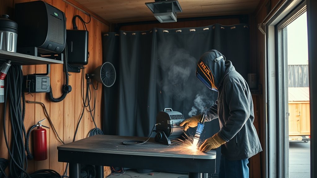
Thin automotive sheet metal can warp, burn through, or lose its shape after only a brief increase in heat. True pulsed MIG welding can improve droplet and puddle control, but it is not a universal low-heat shortcut. The correct setup depends on the welder’s programmed waveform, the panel material, wire diameter, shielding gas, joint design, and the vehicle maker’s repair instructions.
Quick Answer
For thin automotive sheet metal, use the welder manufacturer’s program for the exact metal, wire diameter, and shielding gas—not a universal voltage chart. Test on matching scrap, adjust wire feed and arc-length trim in small steps, use short skip welds, and follow the vehicle maker’s repair procedure before welding any panel.
Key Takeaways
- Confirm that the panel may be welded or sectioned under the model-year-specific OEM body-repair procedure.
- Select the exact material, wire, diameter, and gas program built into the pulsed-MIG machine.
- Do not copy universal voltage, pulse-frequency, background-current, or duty-cycle numbers from another welder.
- Use matching scrap coupons, change one control at a time, and inspect both sides before touching the vehicle.
- Limit heat with accurate fit-up, short skip welds, steady travel, and enough natural cooling time.
- Use C25 shielding gas in a pulse program only when the machine manufacturer or OEM repair procedure specifically approves it.
At a Glance
| Time Required | Allow time for several scrap-coupon tests before the repair; total repair time varies by access, joint length, and cooling needs. |
| Difficulty | Intermediate to advanced; structural, SRS, hybrid, and EV repairs require qualified training and OEM procedures. |
| Tools Needed | Pulsed-MIG-capable welder, approved wire and gas, correct drive rolls and contact tip, PPE, ventilation, clamps, measuring tools, matching coupons, welding blanket, and fire extinguisher. |
| Cost | Varies by machine, gas, wire, PPE, panel access, and repair procedure; confirm compatibility before buying consumables. |
What’s in This Article
- What Is Pulsed MIG Welding?
- Check the Vehicle Repair Procedure Before Welding
- Benefits and Limits of Pulsed MIG
- Wire Size and Filler Selection
- Choose the Correct Shielding Gas
- Voltage, Wire Speed, Trim, and Machine Programs
- How to Dial In Pulsed MIG on Scrap
- Pulse Frequency and Waveform Controls
- Fit-Up and Welding Technique
- Troubleshooting
- Inspection and Corrosion Protection
- Setup Records and Resources
- Frequently Asked Questions
- Conclusion
- Sources
Warning: Do not weld a vehicle panel until you have identified the metal and checked the model-year-specific body-repair procedure. Remove or shield combustible trim, coatings, seam sealer, wiring, fuel-system parts, batteries, and electronic components as directed. Hybrid and EV high-voltage work must be handled by trained personnel using the OEM disabling and verification procedure.
What Is Pulsed MIG Welding and Why Use It for Automotive Sheet Metal?
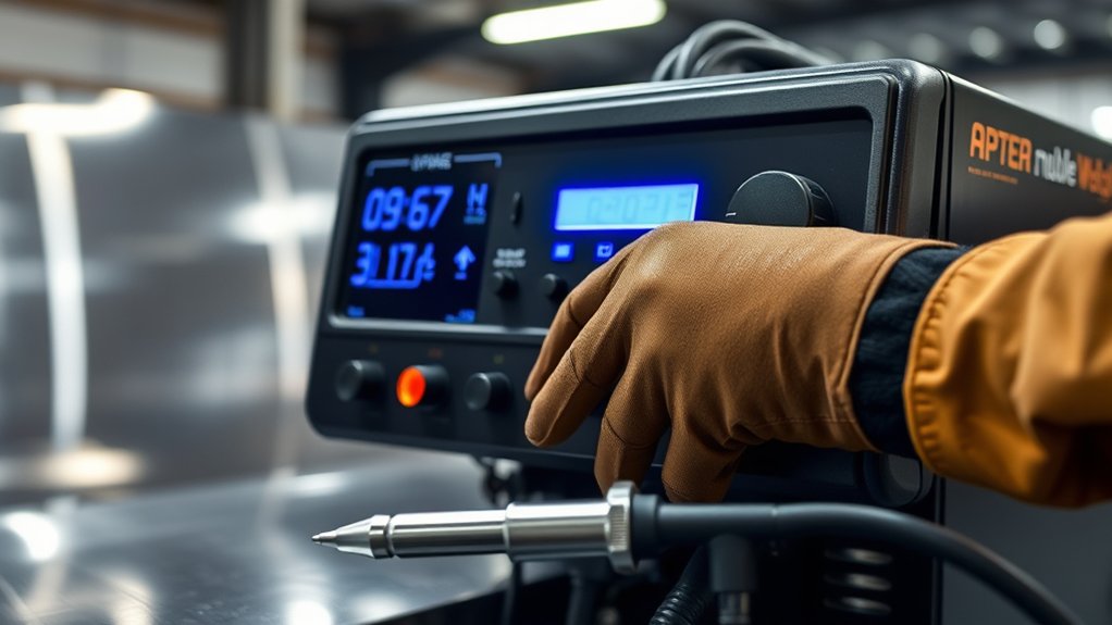
Pulsed MIG, also called pulsed-spray gas metal arc welding or GMAW-P, uses a power source that rapidly changes between a high peak current and a lower background current. The peak portion transfers a controlled droplet of wire. The background portion keeps the arc lit while reducing the average current.
This differs from conventional short-circuit MIG, where the wire repeatedly touches the weld pool, and from manually tapping the trigger to make a row of short tacks. It also differs from pulse TIG and double-pulse MIG. These processes may all control heat in some way, but they use different equipment, transfer behavior, shielding gas, and settings.
Modern pulsed-MIG systems are often synergic. After you select the material, wire type, wire diameter, and shielding gas, the machine coordinates several parts of the waveform as wire speed changes. Miller’s pulsed MIG process guide explains that peak current transfers the droplet while background current maintains the arc.
Pulsed MIG can reduce spatter and provide a controlled, continuously lit arc. It can also reduce heat input compared with conventional spray transfer when the higher travel speed and programmed waveform are suitable for the joint. It is not automatically cooler than a properly tuned short-circuit process, however, and it may be too fluid or aggressive for some hand-welded cosmetic patches.
Note: A “pulse” button does not guarantee that every wire, gas, or panel thickness is supported. The selected program must match all four items: base metal, filler alloy, wire diameter, and shielding gas.
Check the Vehicle Repair Procedure Before Welding
Settings come after repair-method verification. A thin-looking outer panel may sit over reinforcements, airbag parts, wiring, adhesives, or high-strength steel. The approved joint may require squeeze-type resistance spot welding, MIG brazing, rivets and adhesive, panel bonding, plug welds, or complete part replacement instead of a continuous fusion weld.
Identify the Panel and Metal
- Confirm the year, make, model, and exact panel. Similar-looking vehicles may use different steel grades or joining methods.
- Determine whether the work is cosmetic or structural. A mild-steel restoration patch is not the same as a sectioning joint in a modern unibody rail, pillar, rocker, or reinforcement.
- Check the OEM body-repair manual. Honda’s high-strength-steel repair guidance, for example, prohibits MAG welding on certain 1,500 MPa parts and limits sectioning according to steel strength and location. Other manufacturers publish their own requirements.
- Measure the actual sheet thickness. Gauge labels can vary by material, and an assembled joint may contain several layers.
- Identify coatings and filler requirements. Zinc-coated steel, stainless steel, aluminum, and silicon-bronze MIG brazing require different preparation, wire, gas, and repair rules.
Prepare the Vehicle Safely
Follow the OEM battery, SRS, electronic-module, and high-voltage procedures before connecting the welder. Do not invent a universal battery-disconnect waiting time. Some vehicles require scans, saved settings, special shutdown steps, or post-repair calibrations.
- Inspect both sides of the weld area for fuel lines, brake lines, refrigerant lines, wiring, batteries, airbag inflators, trim, foam, sound deadener, seam sealer, and cavity wax.
- Remove combustible material when the repair procedure requires removal. Shield nearby parts with an approved welding blanket.
- Keep a suitable fire extinguisher nearby and maintain a fire watch during and after hot work.
- Use local exhaust ventilation and appropriate respiratory protection when required. Paint, zinc, sealers, adhesives, and contaminated metal can create hazardous fumes.
- Do not use chlorinated brake cleaner or another chlorinated solvent near welding or heat.
- Attach the work clamp to clean metal as close to the repair as the OEM procedure allows. Avoid a current path through electronic modules, bearings, hinges, or restraint components.
Current Honda Prologue EV body-repair information requires model-specific high-voltage disabling and welding blankets around high-voltage components. Treat every hybrid or EV as energized until the approved procedure has been completed and verified by qualified personnel.
Key Benefits and Limits of Pulsed MIG for Thin Automotive Materials
Improved Heat Control
Pulsed MIG can lower average current compared with conventional spray transfer while keeping a stable arc. When the process allows a faster, controlled travel speed, less total heat may enter the panel. This can reduce the heat-affected area and help limit burn-through.
The result still depends on fit-up, joint length, travel speed, wire size, and dwell time. Holding the arc in one location will overheat thin metal even when pulse mode is active.
Reduced Distortion Risk
All fusion welding causes local expansion and shrinkage. Flat, unsupported sheet is especially prone to oil-canning and warping. Pulse can help, but weld sequence remains critical.
Clamp the joint accurately, place initial tacks across the panel, and move between distant areas instead of completing one section at a time. Allow the panel to cool naturally between rounds. Do not quench a structural repair unless the vehicle maker’s procedure permits it.
| Potential Benefit | Important Limitation |
|---|---|
| Controlled droplet transfer | Requires a compatible power source, wire, gas, and waveform program. |
| Less spatter than globular transfer | Wrong gas or excessive arc length can still create an unstable arc. |
| Lower average current than conventional spray | It is not automatically cooler than a short, properly tuned short-circuit tack. |
| Steady, continuously lit arc | The fluid puddle may be difficult to control on a wide gap or unsupported edge. |
Enhanced Weld Quality
A correct pulse program can produce a consistent bead with good wetting and little spatter. It cannot compensate for rust, paint, an incorrect filler alloy, a loose ground, poor gas coverage, or a large uneven gap.
For body-panel work, weld quality also includes panel shape, backside fusion, low grinding heat, and restored corrosion protection. A smooth-looking bead on the visible side is not enough.
What Wire Sizes Work Best for Pulsed MIG?
The correct wire diameter is the one supported by the machine’s pulse program and appropriate for the joint. A 0.023-inch or 0.6 mm steel wire is often useful for conventional short-circuit welding on very thin mild steel, but not every pulsed-MIG machine has a validated waveform for it.
Some pulse systems use 0.030-inch or 0.8 mm wire, while others are optimized around 0.035-inch or 0.9 mm wire. A larger wire is not automatically too hot because a pulsed waveform can control transfer at lower average current. The final choice must match the machine chart or operator manual.
| Application | Possible Filler | Selection Rule |
|---|---|---|
| Ordinary mild-steel cosmetic patch | ER70S-series steel wire in a machine-supported diameter | Use the smallest diameter with a validated program and enough joint fusion. |
| OEM-specified high-strength-steel joint | Wire with the minimum tensile strength specified by the OEM | Do not assume common ER70S-6 wire is strong enough for every steel grade. |
| OEM-specified MIG-brazed joint | Usually an approved silicon-bronze wire | Use only where the body-repair procedure calls for MIG brazing; it is not a substitute for every fusion weld. |
| 304 stainless component | ER308L may be suitable | Confirm the base alloy, service conditions, gas, and repair procedure first. |
| Aluminum panel or component | Alloy-specific aluminum wire | Use the approved filler, feed system, gas, and pulse program for that alloy. |
Pro Tip: Install the contact tip, liner, drive-roll groove, and drive tension specified for the selected wire. An excellent pulse program cannot correct erratic wire feeding.
Products Worth Considering

ER70S-6 MIG WIRE: It's the most common wire of the copper-coated mild steel GMAW (MIG) wires for single or multiple pass welding.

ER70S-6 PERFORMANCE: This .023 MIG welding wire supports precise arc control and low spatter for single-pass and multi-pass welding.

E71T-GS FLUX CORE WIRE: This self-shielding, AWS E71T-GS flux-cored wire excels due to its advanced core design, delivering exceptional arc stabilization and high feedability for effortless welding. The core also incorporates powerful deoxidizing agents, ensuring clean, reliable welds even when welding through light rust or mill scale.
Choose the Correct Shielding Gas
Shielding gas changes arc stability, droplet transfer, penetration shape, oxidation, and the waveform a machine can support. The gas printed on the cylinder must match the gas selected in the machine program.
Lincoln Electric’s pulsed-spray transfer guide states that true axial and pulsed-spray transfer requires an argon mixture containing 18% carbon dioxide or less. A 75/25 argon-CO2 blend contains 25% CO2, so it should not be treated as a universal pulsed-spray gas.
| Material or Process | Gas Guidance |
|---|---|
| True pulsed-spray steel | Use the argon-rich blend listed for the exact pulse program. A 90/10 argon-CO2 blend is common, but the machine may specify another blend containing 18% CO2 or less. |
| Conventional short-circuit mild steel | C25 is common, but selecting C25 does not turn a short-circuit process into true pulsed-spray transfer. |
| OEM MAG repair | Use the blend permitted by the vehicle maker and welding-equipment program. Some OEM procedures accept C25 for specific MAG welds. |
| Silicon-bronze MIG brazing | Commonly uses 100% argon, but follow the OEM repair procedure and welder program. |
| Aluminum | Use the specified argon or argon-helium program. Do not use a CO2-containing steel gas. |
| Stainless steel | Use the precise argon-rich blend listed for the stainless program and filler alloy. |
Products Worth Considering

All HP cylinders come with a 10 year hydrotest date stamped.

WIDE APPLICATION: It easily connects to Argon, Helium, and Argon/CO₂ mixed gas tanks via the CGA-580 inlet nut. No additional adapters are required. Featuring superior airtight and leak-proof performance, it achieves stable and sealed gas supply with minimal gas loss. This regulator is ideal for MIG/TIG welding, chemical processing, general industrial use, and electronics industry applications.

APPLICATION: The ARCCAPTAIN gas pressure regulator can be used with argon, helium, and carbon dioxide gas tanks.
Key Voltage, Wire Speed, and Trim Settings for Pulsed MIG
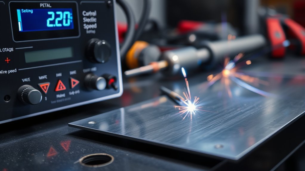
There is no dependable universal combination of 15 to 18 volts and 4 to 7 meters per minute for thin automotive sheet metal. Two machines can display different values while producing similar arcs because their waveforms, calibration, wire, gas, and control logic differ.
Understand Your Machine Control Type
- Synergic pulse: You select material, wire, diameter, and gas. Wire speed or material thickness becomes the main setting, and the machine coordinates voltage and waveform controls.
- Synergic pulse with trim: Wire speed sets deposition and approximate current. Trim changes arc length around the programmed baseline.
- Manual pulse: The machine may expose peak current, background current, frequency, pulse width, or duty cycle. Start with the manufacturer’s procedure rather than a generic percentage.
- Preset automotive or MIG-braze program: Use the precise wire and gas listed for the program and follow the OEM test-weld procedure.
Recommended Voltage or Arc-Length Settings
On a synergic pulsed-MIG machine, the voltage display may be an output value rather than the main setting. Begin at the machine’s recommended thickness or wire-speed value. Leave trim at its programmed neutral position for the first coupon unless the manual says otherwise.
- If the arc repeatedly touches or shorts into the puddle, verify gas and program selection first. A small increase in arc-length trim may help.
- If the arc is long, harsh, or prone to edge melting, verify contact-tip-to-work distance and reduce trim slightly.
- If the bead is tall and poorly tied into the edges, do not assume that voltage alone is the problem. Check wire speed, travel speed, polarity, contamination, and gas.
Optimal Wire Speed
Wire speed affects deposition rate and usually drives the machine’s commanded current. Select the lowest manufacturer-supported starting point that still produces stable transfer and adequate fusion on the matching coupon.
Increase wire speed in small steps when the coupon lacks fusion and the machine remains within its supported pulse range. Reduce it when the puddle becomes too large, the panel edge collapses, or travel speed cannot keep up. Recheck trim after a meaningful wire-speed change because the ideal arc length may also change.
Material Thickness Considerations
Actual sheet thickness is only one input. Also account for:
- Joint type: Butt joints, laps, plug welds, edge welds, and MIG-brazed holes need different procedures.
- Number of layers: A flange with two or three layers draws heat differently from one exposed sheet.
- Joint gap: An uneven gap raises the chance of burn-through and inconsistent penetration.
- Coatings: Zinc, paint, adhesive, sealer, oxidation, and contamination can destabilize the arc and create fumes.
- Panel shape: A crown or flange resists distortion better than a large flat unsupported area.
- Backside access: You must be able to inspect for fire, burn-through, incomplete fusion, and damaged protection.
The safest starting setting is not a copied voltage number. It is the correct machine program followed by a test weld on metal that matches the actual panel and joint.
How to Dial In Pulsed MIG Settings on Matching Scrap
- Verify the approved repair method. Confirm the panel material, strength, joint location, weld type, filler, and gas in the OEM procedure.
- Prepare representative coupons. Use the same alloy and thickness as the panel. Reproduce the joint type and gap as closely as possible.
- Prepare the machine. Install the correct polarity, liner, drive rolls, contact tip, wire, and shielding gas. Check for leaks and secure the cylinder.
- Select the exact pulse program. Match the material, filler alloy, wire diameter, and gas. Start at the machine’s recommended material-thickness or wire-speed setting.
- Make a short test weld. Keep the gun angle, contact-tip-to-work distance, travel direction, and joint position similar to the actual repair.
- Inspect both sides. Look for stable fusion, consistent wetting, porosity, excessive reinforcement, undercut, burn-through, and backside heat damage.
- Change one control at a time. Adjust wire speed or trim by one small step, repeat the coupon, and record the result. Do not change gas, wire speed, trim, and travel speed together.
- Confirm repeatability. Repeat the best setting after the coupon has cooled. For an OEM repair, perform any required destructive or peel test on separate coupons before welding the vehicle.
- Transfer the setup carefully. Match the panel fit-up and welding position to the coupon, then use the approved tack, skip, plug-weld, or brazing sequence.
Pro Tip: Photograph the machine screen and label the coupon with the wire, gas, wire speed, trim, program name, joint gap, and travel direction. A bead that cannot be reproduced is not a finished setup.
How Can You Adjust Pulse Frequency for Better Weld Quality?
Many synergic machines do not let the operator set pulse frequency directly. The program changes frequency, peak current, peak time, and background current together as wire speed or trim changes. This is why a fixed recommendation such as 25% background current or a 40% duty cycle should not be moved from one machine to another.
Lincoln’s waveform guidance notes that increased frequency tends to narrow the arc cone, while decreased frequency tends to broaden it. The same guidance also explains that waveform components influence one another. Frequency is therefore a fine-tuning control, not an independent penetration dial.
| Control | What It Changes | Adjustment Guidance |
|---|---|---|
| Synergic program | Coordinates the complete waveform for the selected wire and gas. | Choose the correct program before changing any fine control. |
| Arc-length trim | Lengthens or tightens the arc around the programmed baseline. | Move one small step at a time and retest the coupon. |
| Frequency or arc control | May change arc-cone focus, droplet timing, and puddle behavior. | Use only within the manufacturer’s recommended range; do not equate higher frequency with deeper penetration. |
| Peak, background, or pulse width | Changes droplet transfer, arc stability, and average energy. | Begin with the supplied waveform or welding procedure and avoid universal percentages. |
| Double pulse | Modulates the pulse program to create alternating heat and deposition patterns. | Use only when the machine program supports the material and the visual bead pattern serves the repair. |
Fit-Up and Welding Technique for Thin Body Panels
Fit-up often determines whether a thin-sheet weld succeeds. Trim the patch carefully, remove contamination as required, and keep the joint gap even. Do not force a badly shaped patch into place with heavy clamp pressure because the stored stress can pull the panel out of shape as the weld cools.
Tack and Skip Welding
Place initial tacks at separated points so the panel cannot move. Continue by adding brief welds in distant areas rather than closing one end of the seam. Miller’s auto-body sheet-metal guide emphasizes accurate fit-up, closely spaced tacks, short weld segments, and cooling time to control distortion.
A true pulse program may support a short continuous segment, but that does not mean a long uninterrupted pass is suitable for a flat automotive panel. Follow the approved joint sequence and stop when heat spreads beyond the immediate weld area.
Gun Position and Travel
- Use the polarity specified for the wire and process.
- Maintain the contact-tip-to-work distance recommended for the pulse program; pulse often uses a different distance from short-circuit MIG.
- Keep the gun angle and travel speed consistent.
- Avoid excessive weaving on thin sheet. Direct the arc where fusion is needed and keep the puddle small.
- Do not use the arc to bridge a large gap. Correct the patch fit first.
- Keep the work clamp connection clean, secure, and close to the repair.
Common Pulsed-MIG Problems and How to Fix Them
Correct the setup and preparation before chasing advanced pulse controls. Change one variable at a time and repeat the test on a cooled coupon.
| Problem | Likely Causes | What to Check |
|---|---|---|
| Burn-through | Large gap, excessive dwell, wire speed too high, long arc, slow travel, unsupported edge, or wrong program. | Correct the gap, shorten each weld, verify wire and gas program, reduce heat in one small step, and allow cooling. |
| Cold lap or poor fusion | Insufficient energy, travel too fast, contamination, poor torch aim, or excessive contact-tip distance. | Clean the coupon, confirm polarity and gas, restore the recommended distance, and raise wire speed or energy slightly. |
| Tall or convex bead | Wire deposition too high for arc length and travel speed, poor wetting, or wrong gas. | Verify the program, reduce wire speed or increase trim slightly, and maintain a steadier travel speed. |
| Porosity | Gas leak, draft, blocked nozzle, contaminated metal, wet wire, paint, zinc, oil, or sealer. | Check gas delivery and connections, clean the nozzle and joint, shield drafts, and remove coatings as the repair procedure requires. |
| Spatter or unstable transfer | Gas does not match the program, wrong polarity, erratic wire feed, loose ground, or excessive arc length. | Confirm the cylinder blend and selected program, inspect drive rolls and tip, tighten connections, and reset trim. |
| Wire burnback or birdnesting | Restricted liner, incorrect tip, excessive drive pressure, poor spool setup, or unsuitable aluminum feed system. | Service the feed path and use the manufacturer-approved consumables and tension. |
| Panel warping | Long welds, concentrated sequence, grinding heat, clamp stress, or inadequate cooling time. | Use separated tacks and short segments, let the panel cool naturally, and avoid overheating while grinding. |
Inspect and Protect the Repair
Inspect the Weld
Inspect the visible and backside surfaces whenever access allows. Look for complete fusion, a consistent bead, no pinholes, no cracks, no unfilled craters, no severe undercut, and no melted panel edge. Check the surrounding vehicle for heat damage, smoldering sealer, damaged wiring, and hidden sparks.
A cosmetic appearance does not prove structural strength. For collision repair, confirm the required weld count, hole size, spacing, location, filler strength, and test-coupon result in the OEM procedure.
Control Grinding Heat
Remove only the weld reinforcement needed for the repair. Keep the grinder moving and pause before the panel becomes hot. Excess grinding can thin the base sheet, weaken the joint, and cause as much distortion as welding.
Restore Corrosion Protection
After the weld passes inspection and cools, restore every protective material required by the repair procedure. This may include weld-through primer in approved locations, epoxy primer, seam sealer, adhesive, undercoating, cavity wax, paint, or replacement insulation. Protect both sides of the joint; an uncoated backside can corrode even when the visible repair looks complete.
Tips and Resources for Better Pulsed-MIG Technique
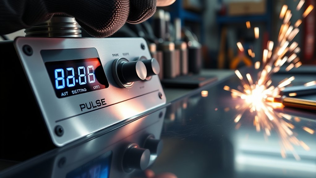
Repeatable results come from controlled testing rather than guesswork. Keep coupons from successful and failed tests so you can compare bead shape, backside fusion, heat tint, and distortion.
| Record This Item | Why It Matters |
|---|---|
| Machine and program name | Pulse waveforms are not interchangeable between machines. |
| Base metal and measured thickness | The coupon must represent the actual panel. |
| Wire alloy and diameter | The machine waveform and joint strength depend on both. |
| Shielding-gas blend | Gas controls transfer behavior and must match the selected program. |
| Wire speed and trim | These are the primary operator controls on many synergic machines. |
| Joint gap and position | A flat lap coupon does not represent an overhead butt joint or open edge. |
| Gun angle, travel direction, and contact-tip distance | Technique can change heat, wetting, and gas coverage. |
| Front and backside inspection result | The visible bead alone cannot confirm fusion or hidden damage. |
Note: Pulse is not always the best process. Depending on the panel and approved repair, short-circuit MIG, TIG, resistance spot welding, MIG brazing, rivet bonding, adhesive bonding, or full panel replacement may provide the correct result.
Frequently Asked Questions
What settings should you use to weld thin automotive sheet metal?
Select the machine program for the exact material, wire diameter, and gas. Start at the manufacturer’s recommended thickness or wire-speed value with neutral trim, then test on matching scrap. Do not rely on a universal voltage, frequency, background-current, or duty-cycle number.
Can you pulse MIG with 75/25 shielding gas?
Use 75/25 only when the exact pulse program or OEM repair procedure approves it. C25 is common for short-circuit steel, but its 25% CO2 content is above the 18% maximum Lincoln lists for true axial and pulsed-spray transfer. Argon-rich blends such as 90/10 are more typical for pulsed steel.
How do you weld thin sheet metal without warping it?
Use accurate fit-up, separated tacks, short weld segments, consistent travel, and natural cooling time. Move between distant areas rather than completing one section at a time. Control grinding heat as carefully as welding heat.
Is 7018 good for thin automotive sheet metal?
A 7018 stick electrode is generally unsuitable for thin cosmetic body panels because the process and common electrode sizes make heat and puddle control difficult. Use the repair process and filler specified by the vehicle maker or the restoration procedure.
Why does my pulse weld burn through sheet metal?
Common causes include a wide joint gap, excessive dwell, slow travel, too much wire speed or arc length, an unsupported edge, or the wrong wire-gas program. Correct fit-up first, then reduce heat in one small step and retest on matching scrap.
Is pulsed MIG always better than short-circuit MIG for body panels?
No. Pulsed MIG offers controlled transfer and low spatter, but its continuously lit, fluid arc may be harder to manage on a thin open edge or uneven gap. Short-circuit MIG and brief skip tacks may be better for some cosmetic patches, while OEM structural repairs may require another joining method.
Can you weld galvanized automotive steel?
Only when the OEM repair method permits it. Prepare the weld area as specified, use suitable ventilation and PPE, and restore corrosion protection afterward. Zinc coatings can contaminate the weld and create hazardous fumes when heated.
Should you disconnect a vehicle battery before welding?
Follow the model-specific OEM procedure rather than a universal rule. Many procedures require a controlled 12-volt battery disconnect and additional SRS or module steps. Hybrid and EV high-voltage systems require trained personnel, proper disabling, lockout, and voltage verification.
Safety Disclaimer: This article provides general information, not a vehicle-specific repair procedure or welding qualification. Welding exposes you to heat, ultraviolet radiation, fumes, electricity, compressed gas, fire, and vehicle-system hazards. Follow the welder manual, OSHA requirements, and the current OEM service and body-repair information. Obtain qualified help when the repair involves structural parts, restraint systems, fuel systems, batteries, hybrids, or high-voltage vehicles.
Conclusion
Pulsed MIG can provide a clean, controlled arc on thin automotive sheet metal, but successful settings cannot be reduced to one voltage, wire speed, pulse frequency, or background-current percentage. Begin with the approved vehicle repair method and the welder’s exact material-wire-gas program. Tune on matching coupons, inspect both sides, control heat with fit-up and weld sequence, and restore corrosion protection after the joint passes inspection.
For a cosmetic mild-steel patch, pulse may reduce spatter and improve control when the machine supports the wire and gas. For a modern structural repair, the OEM procedure—not a generic settings chart—decides whether pulsed MAG, MIG brazing, spot welding, adhesive bonding, or panel replacement is allowed.
Sources
- Miller Electric — Guide to Pulsed MIG Welding in Manufacturing — pulsed-spray operation, synergic controls, shielding gases, and technique.
- Lincoln Electric — Pulsed Spray Metal Transfer — waveform interaction, frequency effects, and argon-rich gas requirements.
- Miller Electric — MIG and TIG Welding Auto Body Sheet Metal — patch fit-up, tack sequence, short welds, cooling, and grinding control.
- Occupational Safety and Health Administration — Welding, Cutting, and Brazing Hazards — fumes, ultraviolet radiation, burns, eye injuries, electrical shock, and protective practices.
- American Honda — High-Strength-Steel Body Repair Information — OEM welding restrictions, filler strength, MIG brazing, MAG welding, and prohibited repairs.
- American Honda — 2024–26 Prologue Body Repair Information — high-voltage disabling, shop safety, welding blankets, and vehicle-specific repair procedures.