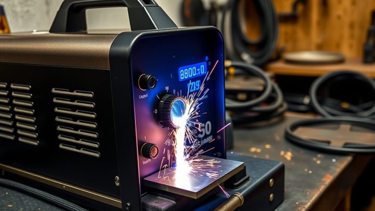
Most 30 to 60 A plasma cutters are calibrated to 90–120 PSI and need 4–7 CFM of clean, dry air to keep the arc stable. Whether you use a built-in or external compressor, the spec match matters. Pressure, flow, and filtration are critical. Moisture or oil in the line raises dross and doubles tip wear. The right dryer, regulator, and tank size can make or break your cut quality. Here’s how to choose the right setup.
Compressed air for plasma cutters provides the high-velocity gas jet needed to ionize the arc and blow away molten metal. Most systems require 90–120 PSI and 4–8 SCFM. Keeping the air clean and dry is essential to prevent consumable erosion and maintain a stable cutting arc.
Key Takeaways
- Pressure & Flow: Standard cutters need 90–120 PSI, and the compressor should deliver at least 1.5× the cutter’s rated airflow (typically 4–8 CFM).
- Air Quality: Moisture and oil destroy plasma performance. A coalescing filter and dryer will extend consumable life significantly.
- Tank Size: A 20–30 gallon tank works for short, intermittent cuts. For continuous duty, go with 60 gallons or more.
- Compatibility: External compressors deliver better cooling and drier air than built-in units, especially for thicker materials.
Why Plasma Cutters Rely on Compressed Air
Several gases can work for plasma cutting, but most systems use compressed air. Air delivers the ionized, high-velocity jet needed to cut through metal while also cooling the torch and consumables.
Air is popular because it’s cheap, widely available, and thermally consistent across common duty cycles. To meet process demands, your compressed air source needs to hold stable pressure and flow. Typical setpoints are 90–120 PSI at the torch inlet, with available flow at least 1.5× the cutter’s consumption rate. That buffer prevents pressure droop under load.
Choose air for availability and cost; hold 90–120 PSI and 1.5× flow to avoid droop.
Clean, dry air is just as important. Moisture and oil cause arc instability, wider kerf, more dross, and faster nozzle and electrode wear. Use filtration rated to 5 microns or finer, add coalescing separation for aerosols, and install a dryer matched to your dew point target.
Built-in compressors have limits. They’re fine for light-duty cutting but often can’t sustain the airflow needed for thicker sections, continuous duty cycles, or repeatable cut quality.
How Compressed Air Creates the Plasma Arc

The pilot arc ionizes compressed air inside the nozzle, creating a conductive channel that reaches over 20,000°C to melt metal.
Arc constriction depends on nozzle orifice geometry and swirl ring design. These increase current density and arc stiffness, giving you a narrower kerf and less dross.
Proper gas flow at the specified pressure and SCFM keeps the arc stable, prevents thermal overload, and protects consumables and cut quality.
Ionization in Nozzle
When compressed air enters the plasma cutter‘s constricted nozzle, a high voltage ionizes the gas stream. This converts it into a high-temperature, electrically conductive plasma jet.
You control ionization by managing the air supply, keeping air clean, and regulating pressure and flow. The nozzle geometry focuses the stream while the electric field strips electrons, creating a conductive path that sustains the arc and heat density required for cutting.
- Maintain 90–120 PSI at the torch inlet to stabilize arc initiation and prevent jet collapse.
- Match SCFM to the tool’s spec to keep ion density high. Insufficient flow causes arc flutter and dross.
- Use dry, oil-free filtration. Contaminants inhibit electron mobility and erode consumables.
- Verify duty-cycle airflow stability. Pressure droop deionizes the column mid-cut.
Arc Constriction Dynamics
Ionization sets the stage. Constriction dynamics turn it into a cutting arc by coupling high-pressure, clean, dry air with the nozzle orifice. This accelerates flow to near-choked conditions, raising velocity, shear, and heat flux at the arc core.
The arc is forced through a calibrated throat. The magnetohydrodynamic pinch (a magnetic squeezing effect on the plasma) intensifies current density and temperature, producing a narrow, high-enthalpy jet.
Compressed air stabilizes the plasma column, minimizes arc wander, and maintains consistent energy density for clean kerf geometry and low dross. Because plasma cutters need airflow above the nameplate CFM, this preserves momentum and thermal balance across the nozzle.
Gas Flow Control
Arc initiation starts electrically, but gas flow control turns it into a sustained cutting plasma by metering clean, dry compressed air at the right pressure and mass flow.
The air compressor must deliver stable pressure and CFM so the plasma column stays hot, constricted, and energy-dense. Regulate supply between 90–120 PSI depending on material thickness, then verify the torch’s dynamic pressure under flow.
Size compressor output at least 1.5× the cutter’s consumption to prevent pressure sag during long cuts. Drying and filtration are non-negotiable for avoiding arc flutter and consumable erosion.
- Set regulator to 90–120 PSI and confirm under-flow readings.
- Verify CFM is at least 1.5× torch demand.
- Use a coalescing filter and dryer for oil and moisture removal.
- Audit duty cycle and hose inner diameter to minimize pressure drop.
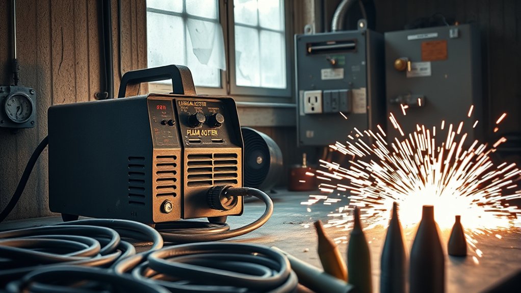
Built-In vs. External Air Compressors

Built-in and external compressors involve a clear trade-off: portability vs. power. Integrated units are compact and suited to light-duty, thin-gauge cuts. Separate compressors deliver higher CFM and PSI for thicker materials.
You also get better air quality control with a standalone compressor. Dedicated filtration reduces moisture and oil, which extends consumable life per manufacturer specs.
Portability and Power
Built-in and external compressors both supply compressed air, but they offer very different trade-offs in portability and power.
If mobility is the priority, a cutter with an integrated compressor reduces setup time and cords. However, the compact tank and duty cycle constrain CFM and PSI, limiting sustained or thick-section cuts.
For higher throughput, external units deliver stronger, steadier airflow and pressure. They support longer cut durations without thermal stress.
- Match airflow: Verify the cutter’s required CFM at operating PSI. Built-ins suit light-duty work; externals meet continuous-load specs.
- Check tank size: Larger reservoirs reduce cycling, stabilize arc quality, and prevent pressure sag on long kerfs.
- Evaluate duty cycle: Integrated systems heat up faster. Externals offload heat more effectively.
Air Quality Control
Power and portability choices only pay off if the air you feed the torch stays clean, dry, and stable at the specified PSI and CFM. Treat air quality control as a hard spec, not a suggestion. Target 10% relative humidity or less at the regulator, under 0.1 mg/m³ oil carryover, and pressure ripple below 3%.
For heavier loads, a separate air source with higher CFM headroom maintains stable flow and allows multi-stage conditioning: intake dryer, particulate/oil coalescer (0.01 µm or finer), desiccant or refrigerated dryer, and then a point-of-use regulator with automatic drain.
Cost and Versatility
A built-in compressor lowers your upfront cost and simplifies setup, but you give up airflow headroom and tool flexibility that an external unit provides.
Integrated units work well on thin sheet metal, where modest CFM keeps the arc stable. For heavier sections, you’ll need sustained compressed air flow and pressure that only external compressors can maintain without duty-cycle interruptions. External systems also let you power other pneumatic tools, which helps consolidate equipment.
Key Specs: CFM, PSI, and Tank Size

For reliable plasma cutting, match your air system to three specs: CFM, PSI, and tank size.
Airflow first. Your compressor’s CFM at 90–120 PSI should exceed the cutter’s consumption by at least 1.5×. If the torch needs 6 CFM, target 9 CFM delivered at operating pressure to prevent sag during long cuts. Most light-to-medium machines run between 4–8 CFM. Thicker materials push you toward the upper range.
Pressure with margin. Keep 100–135 PSI at the compressor to hold 90–120 PSI at the torch after line losses from hoses, fittings, and regulators. Verify pressure at the gun under flow, not static.
Tank size for duty cycle. A 20–30 gallon tank stabilizes short, intermittent cuts. For extended cuts or higher amperage, step up to a 60-gallon tank. This reduces compressor cycling and voltage drop risk.
Common Air Supply Mistakes to Avoid
Even experienced operators make air supply errors that hurt cut quality and shorten consumable life. Here are the most frequent problems and how to fix them.
- Undersized hose diameter: A narrow hose creates pressure drop between the compressor and torch. Use at least 3/8-inch ID hose, and keep runs as short as practical.
- Skipping the water trap: Humidity condenses inside the tank and hose. Without a water separator near the torch, moisture enters the arc and causes erratic cuts.
- Ignoring the duty cycle: Running the compressor at 100% for long periods overheats the motor and drops pressure. Size your compressor so it cycles off regularly.
- Setting pressure by gauge alone: Static gauge readings are higher than dynamic (under-flow) readings. Always confirm PSI while the torch is actually firing.
Ensuring Clean, Dry Air for Longer Consumable Life

Even with the right CFM and PSI, your plasma arc suffers if the air stream carries water, oil, or particulates. You need clean, dry air to protect electrodes and nozzles, stabilize arc geometry, and extend consumable life.
An aftercooler drops discharge temperature, condensing moisture before it reaches the torch. Staged filtration systems then remove liquid, aerosols, and solids down to sub-micron levels. Monitor differential pressure across filters and replace elements on schedule to maintain your target dew point and particle counts.
- Install an aftercooler plus a drainable water separator, coalescing filter (0.01–0.1 µm), and an activated-carbon stage to reduce oil vapor.
- Verify dew point is below ambient line temperature to prevent in-line condensation. Target at least 10°C (18°F) below.
- Use automatic drains. Inspect bowls and replace elements when pressure drop exceeds the manufacturer’s limits.
Matching Compressor Power and Voltage to Your Cutter
When pairing a compressor with your plasma cutter, match airflow and electrical supply before anything else.
Start by checking the cutter’s airflow requirements (SCFM at a specified PSI). Then select a compressor that exceeds that demand. A good rule is to add a 50% buffer. If the torch consumes 4 SCFM, spec a compressor delivering at least 6 SCFM at the stated pressure. This keeps the arc stable and cut quality consistent.
Verify SCFM at the specified PSI, then add 50% overhead for stable, clean plasma cuts.
Confirm voltage compatibility next. For hobby or light-duty use, single-phase 110V compressors are typical. For higher throughput and continuous operation, 220V units provide better efficiency and headroom. If your site power varies, look for models rated for both 110/220V. This lets you match available circuits without derating performance.
Practical Tips for Noise, Portability, and Budget

Plasma cutters can run on various air sources, but you’ll get the best results by choosing a compressor with clear noise, mobility, and cost targets. Start by defining acceptable dB levels, tank size, and duty cycle for your setup. Noise varies widely. Budget units often exceed 60 dB, while quiet compressors can drop to around 40 dB. That difference matters in shops with exposure limits or residential garages.
- Specify noise: Target 40–55 dB for indoor work. Accept 60+ dB only with hearing protection and isolation.
- Match portability to demand: Compact portables work great on-site, but small tanks and lower CFM limit sustained cuts. Plan pauses or pair with a larger reserve tank.
- Right-size tanks to budget and workload: 60 gallons for continuous or industrial duty, 20–30 gallons for light-to-moderate tasks without frequent cycling.
- Prioritize clean, dry air: Add filtration and a regulator to stabilize PSI and CFM. It protects consumables and improves cut quality, according to guidelines from the American Welding Society.
Frequently Asked Questions
Do plasma cutters need compressed air?
Yes, most plasma cutters rely on compressed air to create the plasma arc and cool the torch. Standard systems require 90–120 PSI and 4–8 CFM. Using clean, dry air is critical to prevent consumable damage and ensure stable cutting performance.
How much air pressure do you need for a plasma cutter?
Typical plasma cutters operate between 90–120 PSI. Smaller machines may run near 80 PSI, while industrial systems exceed 115 PSI. Always match the regulator setting to the manufacturer’s specified dynamic pressure for the material thickness you are cutting.
Is a 6 gallon air compressor enough for a plasma cutter?
Generally, no. A 6-gallon compressor lacks the tank capacity to sustain the required 4–8 CFM for more than a few seconds. This leads to rapid cycling, pressure drops that kill the arc, and poor cut quality. A minimum of 20–30 gallons is recommended.
What size air compressor do I need for the Titanium Plasma 65?
For the Titanium Plasma 65, use a compressor with a 20–30 gallon tank for intermittent use, or 60+ gallons for continuous work. Make sure the unit delivers at least 4.0 CFM at 90 PSI to maintain a stable arc without frequent pauses.
Wrapping Up
You do need compressed air for reliable plasma cutting. Keep 90–120 PSI at the torch and meet the cutter’s rated CFM at duty cycle. Many units require 4–7 CFM at 90 PSI. Dry, oil-free air can extend consumable life by up to 50%. Match compressor horsepower, voltage, and duty cycle to your cutter’s load. Use a regulator, desiccant dryer, and a 20–60 gallon tank for stable flow. For shop safety, prioritize low-noise compressors rated at 60–70 dB or below.