An aluminum plasma cutting chart gives you a tested starting point for cut speed, amperage, torch height, pierce delay, arc voltage, gas flow, and kerf. The important detail is that no single chart works for every plasma cutter. Use the chart written for your exact power supply, torch, consumable or cartridge, gas process, and cutting method.
Quick Answer
Start with the aluminum cut chart in your plasma cutter’s current manual. Match the machine, torch, consumable, amperage, gas, material thickness, and handheld or mechanized process. Do not treat generic online amperage or speed ranges as universal settings. Make a test cut, inspect the edge, and change only one variable at a time.
Key Takeaways
- A valid aluminum plasma cutting chart is specific to one machine, torch, consumable, gas process, and cutting method.
- Air-plasma systems commonly cut aluminum with clean, dry, oil-free air; nitrogen, water, and argon-hydrogen processes require compatible multi-gas equipment.
- Use the listed cut height, pierce height, pierce delay, speed, voltage, and kerf as a complete process rather than choosing numbers from different charts.
- Never cut aluminum on or under water unless the table manufacturer has approved the system and hydrogen accumulation is prevented.
- Ventilation, eye and face protection, dry insulated gloves, protective clothing, hearing protection, and fire control are required parts of the setup.
At a Glance
| Time Required | About 10–20 minutes for setup and test cuts before production |
| Difficulty | Intermediate; advanced for CNC height control, multi-gas systems, or water tables |
| Tools Needed | Plasma cutter and manual, correct torch consumable, calipers, test coupon, work clamp, air or approved gas supply, ventilation, and required PPE |
| Cost | Usually limited to test material, consumables, compressed air, or specialty gas; actual cost varies by system |
Warning: Plasma cutting can cause fatal electric shock, fire, burns, eye injury, hearing damage, and hazardous fume exposure. Read the equipment safety manual before use. Keep the work area dry, remove flammable materials, use effective fume extraction, and wear the eye, face, hand, body, foot, and hearing protection required for the process.
How to Read an Aluminum Plasma Cutting Chart

Plasma cutting uses an electrically conductive arc and a high-speed gas stream to melt metal and push it out of the kerf. Aluminum is suitable for plasma cutting, but its thermal conductivity, lower melting temperature, alloy, surface condition, and tendency to distort make consistent parameter control important.
The first step is finding the correct chart. Check all of the following before copying any value:
- Power supply model: A 45-amp chart from one machine is not automatically valid for another 45-amp machine.
- Torch and consumable: Hand torches, machine torches, standard consumables, fine-cut consumables, and cartridge systems use different settings.
- Cutting method: Hand cutting and mechanized cutting have different speed, height, and voltage requirements.
- Gas process: Air, nitrogen, nitrogen/water, and argon-hydrogen processes are not interchangeable.
- Material and thickness: Use the aluminum row that matches the measured plate thickness.
- Quality target: A best-quality setting usually runs slower than a highest-production setting.
A complete machine chart may list cut height, initial pierce height, pierce delay, best-quality speed, production speed, arc voltage, gas flow, and expected kerf. Use these values as one matched process.
The correct starting point is the current cut chart for the exact equipment—not a generic relationship between plate thickness and amperage.
Example Aluminum Plasma Cutting Chart
The table below is a limited example taken from the June 2024 Hypertherm Powermax45/65/85/105 SYNC Cut Charts Guide. It applies only to a Powermax45 SYNC machine-cutting process at 45 A with air and the specified mechanized cartridge. It is not a universal chart for other plasma cutters.
Note: These are best-quality starting values obtained under controlled conditions with the correct electrical supply, gas supply, and new consumables. Verify every value in the latest manual for your own serial number and configuration.
| Aluminum Thickness | Cut Height | Pierce Setup | Best-Quality Speed | Arc Voltage | Reference Kerf |
|---|---|---|---|---|---|
| 1/8 in. | 0.125 in. | 0.150 in.; 0.1 sec | 170 IPM | 142 V | 0.043 in. |
| 1/4 in. | 0.125 in. | 0.150 in.; 0.2 sec | 70 IPM | 146 V | 0.041 in. |
| 3/8 in. | 0.125 in. | 0.150 in.; 0.7 sec | 36 IPM | 147 V | 0.053 in. |
| 1/2 in. | 0.125 in. | Edge start | 21 IPM | 155 V | 0.045 in. |
| 3/4 in. | 0.125 in. | Edge start | 8 IPM | 163 V | 0.033 in. |
This example demonstrates why generic advice such as “use 25–30 amps for 1/8-inch aluminum” is unreliable. The listed process runs at 45 A, while speed, pierce method, voltage, and kerf change with thickness.
The same manufacturer also publishes higher-production settings. Those settings can make more parts per hour, but they may not provide the lowest dross, best angle, or smoothest finish. Begin with the best-quality column unless production speed is the main requirement.
Choose the Gas by System Type

The correct gas depends first on what the plasma system is designed to use. Do not connect an unapproved gas or create a homemade mixture.
Products Worth Considering

Desiccant Air Dryer System: Engineered with a compressor desiccant air filter dryer system that effectively traps water vapor, oil aerosols, and dirt particles from the air supply. This unit functions as a reliable air line dryer, helping to prevent moisture-related damage to pneumatic tools and ensuring smoother operation for workshop projects.
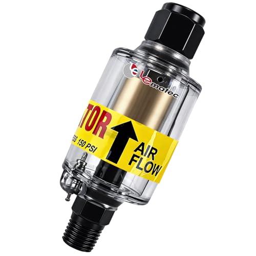
Moisture Protection: 1-micron reusable element removes air compressor oil and water from compressed air systems; essential for precise spray painting and plasma cutting

【Designed for Drying】The Desiccant Air Dryer allows the Air to be Thoroughly Dried and Cleaned before it Enters your Pneumatic Tools. The Desiccant Beads need to be Added to the Metal Bowl. When it needs to be Replaced, the Beads will Change from Blue to Pink.
Air-Plasma Systems
Many portable and light-industrial plasma cutters use clean, dry, oil-free compressed air as the cutting and shielding gas. Air is economical and can produce useful cut quality on aluminum. The edge may be rougher or more oxidized than an optimized multi-gas process, so clean and prepare the edge before critical welding or finishing.
Moisture, compressor oil, dirt, low pressure, or restricted airflow can destabilize the arc and shorten consumable life. Use the filter, dryer, regulator, hose size, inlet pressure, and flow rate stated in the machine manual.
Multi-Gas and High-Definition Systems
Compatible multi-gas systems may use the following processes:
- Nitrogen/nitrogen: Often selected for high-quality cutting of thinner aluminum.
- Nitrogen/water: Available on compatible systems for a smooth finish on thicker aluminum.
- Argon-hydrogen with nitrogen shielding: Used by suitable industrial systems for thick aluminum where greater arc energy is needed.
- Air/air: May remain an economical option when finish requirements allow it.
Hypertherm’s aluminum gas guidance recommends separating air-plasma operation from multi-gas process selection. Oxygen is not a general-purpose aluminum plasma gas, and some air-plasma systems specifically prohibit oxidizing or flammable gases.
Warning: Argon-hydrogen mixtures are flammable-gas processes that require equipment designed for them. Never use H-35, H-2, or another hydrogen-containing fuel-gas process for underwater aluminum cutting.
Water Table Benefits and Explosion Risks

A properly designed water table can reduce airborne dust, sound, glare, and heat around a CNC cutting process. It can also create a severe explosion hazard when aluminum particles, molten droplets, or reaction products generate hydrogen that becomes trapped under the plate or inside part of the table.
The safe approach is not to rely on a generic water level or a single accessory. Before cutting aluminum over water:
- Confirm in writing that the table and fume-control manufacturer permits aluminum cutting.
- Complete the manufacturer’s hydrogen-accumulation risk assessment.
- Use the ventilation, water movement, aeration, chamber design, cleaning schedule, and operating limits specified for that table.
- Prevent large sheets, warped plate, or table structures from trapping gas.
- Inspect and remove aluminum residue as directed by the table manufacturer.
- Do not use a hydrogen-containing cutting gas underwater.
- Never cut aluminum-lithium alloys in the presence of water.
The Hypertherm Safety and Compliance Manual states that aluminum must not be cut underwater or on a water table unless hydrogen accumulation can be prevented. It also directs operators to consult the table manufacturer and qualified experts before beginning the process.
Warning: Do not assume that bubbling at the water surface proves the table is safe. Hydrogen can remain trapped beneath a workpiece or inside a lower chamber and ignite when exposed to the plasma arc or another spark.
Balance Cutting Speed and Amperage

Amperage controls the available arc power, while travel speed controls how long that energy acts on one area of the plate. The two values must match the nozzle or cartridge and the material thickness.
Signs the Torch Is Moving Too Fast
- Sparks spray upward or trail sharply behind the torch.
- The arc fails to pass through the plate.
- The cut stops before the end of the path.
- The lower edge has hard, high-speed dross.
- The cut face shows excessive bevel or an uneven drag line.
Signs the Torch Is Moving Too Slowly
- The kerf becomes wider than expected.
- Heavy, rounded low-speed dross collects under the cut.
- Thin plate warps or discolors from excessive heat.
- Internal corners become washed out.
- Consumables receive unnecessary heat exposure.
Do not compensate for every problem by raising amperage. Use the amperage specified for the installed consumable, then correct airflow, speed, height, consumable condition, and work-lead contact.
Pro Tip: Mark each test coupon with the speed and voltage used. Change one setting at a time and keep the best sample. This produces a reliable shop record for the same alloy, thickness, and machine setup.
Use Arc Voltage to Control Torch Height

On a mechanized plasma table, a torch-height controller can use arc voltage to estimate the distance between the torch and the plate. In general, a longer arc has a higher voltage and a shorter arc has a lower voltage, but the correct relationship is system-specific.
Use the chart voltage as a starting point, then verify the physical cut height. Do not adjust voltage while ignoring the actual distance between the torch and aluminum.
Common causes of incorrect height include:
- Worn electrodes, nozzles, shields, or cartridges.
- Plate that is bowed, warped, or moving during the cut.
- Incorrect ohmic sensing or initial-height sensing.
- Loose torch mounting hardware.
- Incorrect voltage-divider or CNC configuration.
- Slow acceleration in short contours.
Arc voltage often rises as consumables wear. Repeatedly increasing voltage to preserve the same physical height can hide worn parts, so inspect the consumables before changing the program.
Set Pierce Height and Delay from the Chart
Piercing sends molten aluminum upward before the arc breaks through the plate. The initial pierce height keeps this spray farther from the nozzle or cartridge. After the pierce delay, the torch moves down to its normal cut height and begins traveling.
Do not use one pierce-height ratio for every machine. Depending on the process, the chart may call for 120%, 150%, 200%, 250%, another value, or an edge start.
When to Use an Edge Start
Use an edge start when the chart lists “edge start,” when the plate exceeds the machine’s pierce capacity, or when the manufacturer requires it for that thickness. Position the torch so the arc can exit through the edge rather than forcing molten metal back toward the consumable.
How to Reduce Pierce Damage
- Use the exact pierce height and delay from the current chart.
- Do not begin motion before the arc has passed through the plate.
- Do not leave the torch stationary longer than required.
- Check that the CNC descends to cut height only after the pierce.
- Inspect the shield and nozzle for aluminum spatter.
- Replace damaged or out-of-round consumables.
A pierce that is too low can coat or damage the consumable. A pierce that is too high may fail to transfer cleanly or may stretch the arc beyond the approved range.
Measure and Compensate for Kerf Width

Kerf is the width of material removed by the plasma arc. A CNC program offsets the toolpath by part of that width so the finished part remains the correct size.
The kerf value in a cut chart is a starting reference. Actual kerf can change with:
- Travel speed.
- Actual torch height.
- Amperage and consumable type.
- Consumable wear.
- Aluminum alloy and thickness.
- Gas quality and flow.
- Machine motion and corner slowdown.
To verify kerf, make a straight test cut under production conditions and measure the opening with suitable calipers or another accurate method. Enter the measured value into the CNC or CAM software, cut a test part, and confirm the finished dimensions.
For closely nested parts, account for both kerf and heat input. Thin webs between cuts can overheat, move, or distort even when the programmed offset is correct.
Step-by-Step Aluminum Plasma Cutter Setup

- Identify the aluminum. Confirm the alloy when possible, measure the true thickness, and check for coatings, paint, plastic film, oil, solvent, or unknown contamination.
- Confirm machine capacity. Check the recommended cut, severance, and pierce ratings. Do not confuse an edge-start severance rating with a clean piercing capacity.
- Find the correct chart. Match the power supply, torch, cartridge or consumable, amperage, gas, and handheld or mechanized process.
- Inspect consumables. Replace cracked, burned, pitted, obstructed, or out-of-round parts according to the manual.
- Prepare the gas supply. Confirm the approved gas, pressure, flow, filtration, dryness, hose size, and regulator.
- Attach the work lead. Connect it to clean, conductive metal as directed by the equipment manufacturer.
- Set the chart values. Enter the listed speed, cut height, pierce height, pierce delay, amperage, voltage, and kerf.
- Check safety controls. Start ventilation, remove flammables, position screens, verify grounding, and put on the required PPE.
- Make a test cut. Use scrap from the same alloy and thickness when possible.
- Inspect the result. Check penetration, dross, bevel, edge roughness, top-edge rounding, kerf, hole shape, and dimensional accuracy.
- Change one variable. Adjust speed or another manufacturer-approved value in a small step. Do not change several settings at once.
- Record the final process. Save the machine, cartridge, alloy, thickness, speed, voltage, height, gas, and measured kerf.
Note: Recommended cut capacity describes a quality production cut. Severance capacity describes the maximum thickness the machine can separate at a slow speed with more cleanup. Pierce capacity is the maximum thickness at which the machine can safely start in the middle of the plate. These ratings are not interchangeable.
Troubleshooting Aluminum Plasma Cuts

| Symptom | Likely Causes | First Checks |
|---|---|---|
| Arc does not penetrate | Speed too high, insufficient output, low airflow, worn consumables, poor work connection, plate beyond capacity | Confirm chart row, gas pressure under flow, work lead, consumables, and machine rating |
| Heavy bottom dross | Speed too slow or too fast, incorrect height, worn consumables, poor gas quality | Return to chart speed and height, then adjust speed in small steps |
| Sparks spray upward | Travel too fast, arc not fully penetrating, low amperage for installed consumable, poor air supply | Slow to the chart value and verify gas flow and consumable match |
| Excessive bevel | Torch too high, incorrect direction, worn nozzle, speed error, loose torch, damaged motion system | Measure cut height, inspect consumables, verify torch squareness and travel direction |
| Wide kerf or warping | Speed too slow, torch too high, excess corner slowdown, poor cut order, too much heat concentration | Increase speed within the approved range and revise sequencing or lead-ins |
| Short consumable life | Wet or oily air, low pierce height, incorrect pressure, too many failed starts, excessive pilot arc, spatter | Service filtration, verify pierce setup, inspect the torch, and follow replacement criteria |
| Poor hole quality | Hole too small for the process, excessive speed, poor lead-in, no corner or hole-speed control | Use the manufacturer’s hole-cutting process or reduce speed only as directed by the CAM strategy |
Ventilation and Surface Preparation
Plasma cutting produces airborne metal fume and process gases. The OSHA welding and cutting fume guidance recommends source capture or local exhaust close to the plume. Working outdoors does not guarantee safe exposure levels.
Remove paint, solvent residue, plastic film, oil, and unknown coatings from the cutting zone when it is safe to do so. Check the product safety data before heating coated or treated aluminum. Respiratory protection may be required when ventilation and other controls cannot keep exposure within applicable limits.
Personal Protective Equipment
Use safety glasses with side protection beneath suitable face and eye protection. Select the filter-lens shade required by the machine manual and applicable workplace standard. Wear dry insulated gloves, flame-resistant clothing that covers exposed skin, suitable footwear, and hearing protection. Keep bystanders behind suitable screens and provide them with appropriate protection.
OSHA identifies molten metal, fumes, harmful radiation, noise, electrical shock, and fire as hazards of plasma arc cutting. Review the applicable OSHA hot-work PPE guidance and local workplace requirements.
Frequently Asked Questions
What settings should I use for plasma cutting aluminum?
Use the aluminum row in the current cut chart for your exact machine, torch, consumable or cartridge, gas, amperage, material thickness, and cutting method. Do not use a generic amperage-to-thickness rule. Begin with the best-quality values, make a test cut, and change only one manufacturer-approved setting at a time.
Can you cut aluminum on a CNC plasma table?
Yes. A CNC plasma table can cut aluminum when the plasma system has the required capacity and the CNC uses the correct speed, height, pierce, voltage, and kerf settings. A downdraft table or an aluminum-approved water table must control fumes safely. Do not use a water table unless hydrogen accumulation is prevented.
How thick can a plasma cutter cut aluminum?
The limit depends on the machine and process. Check four separate specifications: recommended cut capacity, severance capacity, pierce capacity, and any edge-start capacity. A machine may sever a plate that is too thick to pierce cleanly or cut at production quality.
What gas is best for plasma cutting aluminum?
For an air-plasma cutter, use the clean, dry, oil-free air specified by the manufacturer. Compatible multi-gas systems may use nitrogen/nitrogen for thinner aluminum, nitrogen/water for selected thicker processes, or argon-hydrogen with nitrogen shielding for thick material. Use only gases and mixtures approved for the equipment.
Why does my aluminum plasma cut have so much dross?
Common causes include incorrect speed, wrong torch height, worn consumables, wet or oily air, low gas flow, excessive heat, or using settings from the wrong chart. Return to the complete manufacturer process, inspect the consumables and gas supply, then adjust speed in small steps.
Can aluminum be plasma cut over a water table?
Only when the table and cutting-system manufacturers approve aluminum and the design prevents hydrogen accumulation. Never cut aluminum-lithium alloys in the presence of water, and never use a hydrogen-containing fuel-gas process for underwater aluminum cutting.
Conclusion
An aluminum plasma cutting chart is most useful when every value comes from one tested, machine-specific process. Match the power supply, torch, consumable, gas, amperage, material thickness, and cutting method before entering speed, height, pierce, voltage, and kerf settings.
Begin with the best-quality column, make a test cut, and adjust only one approved variable at a time. Correct gas quality, consumable condition, torch height, and work-lead contact before making large speed or voltage changes. For water-table cutting, proceed only with manufacturer-approved hydrogen controls and never improvise the safety system.
Sources
- Hypertherm Powermax45/65/85/105 SYNC Cut Charts Guide, Revision 4 — machine-specific aluminum cut speed, height, voltage, pierce, gas-flow, and kerf data.
- Hypertherm: Plasma Cutting Aluminum — air-plasma and multi-gas selection, edge quality, and underwater-cutting guidance.
- Hypertherm Safety and Compliance Manual — electric shock, fire, compressed gas, fume, hydrogen, and aluminum-lithium warnings.
- OSHA: Controlling Hazardous Fume and Gases During Welding — source ventilation, coatings, confined spaces, and respiratory controls applicable to plasma cutting.
- OSHA Hot-Work PPE Guidance — eye, face, hand, foot, body, hearing, electrical, radiation, and hot-metal protection.
- Miller: Selecting and Operating a Handheld Plasma Cutter — recommended-cut and severance-capacity distinctions.