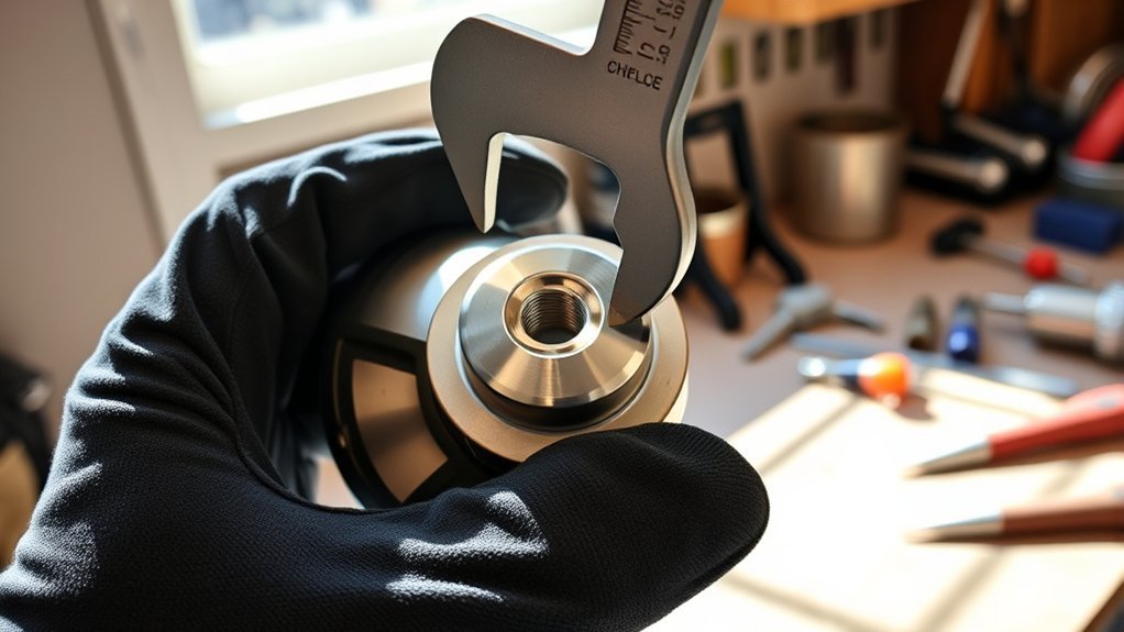
A loose or incorrectly mounted angle grinder wheel can wobble, bind, damage the mounting hardware, or break during use. Safe installation starts with identifying the correct wheel, guard, backing flange, and lock nut for your grinder. You then need to seat each part correctly, tighten it with the supplied wrench, and test the setup before the wheel touches the workpiece.
Quick Answer
Disconnect the grinder from power, confirm that the wheel, flange, lock nut, and guard match the tool, and seat the wheel flat on the backing flange. Install the lock nut in the orientation shown in your manual, engage the stopped spindle lock, and tighten securely with the supplied pin spanner without using extra leverage.
Key Takeaways
- Unplug the grinder or remove its battery before touching the wheel, nut, flange, spindle, or guard.
- Match the wheel’s diameter, arbor, maximum RPM, mounting hardware, and guard to your exact grinder.
- Do not rely on a universal raised-side or flat-side rule for the lock nut; orientation can vary by wheel type and thickness.
- Tighten the lock nut securely with the supplied wrench, but do not use a pipe, hammer, extension, or excessive force.
- Spin the wheel by hand and perform a guarded no-load test before cutting, grinding, or sanding.
At a Glance
| Time Required | About 5 minutes |
| Difficulty | Easy, provided that the correct parts and instructions are available |
| Tools Needed | The grinder’s supplied pin spanner or manufacturer-approved lock-nut wrench |
| Cost | Usually $0 when the original flange, nut, guard, and wrench are present; replace damaged parts with model-compatible parts |
Why Proper Lock-Nut and Flange Installation Matters
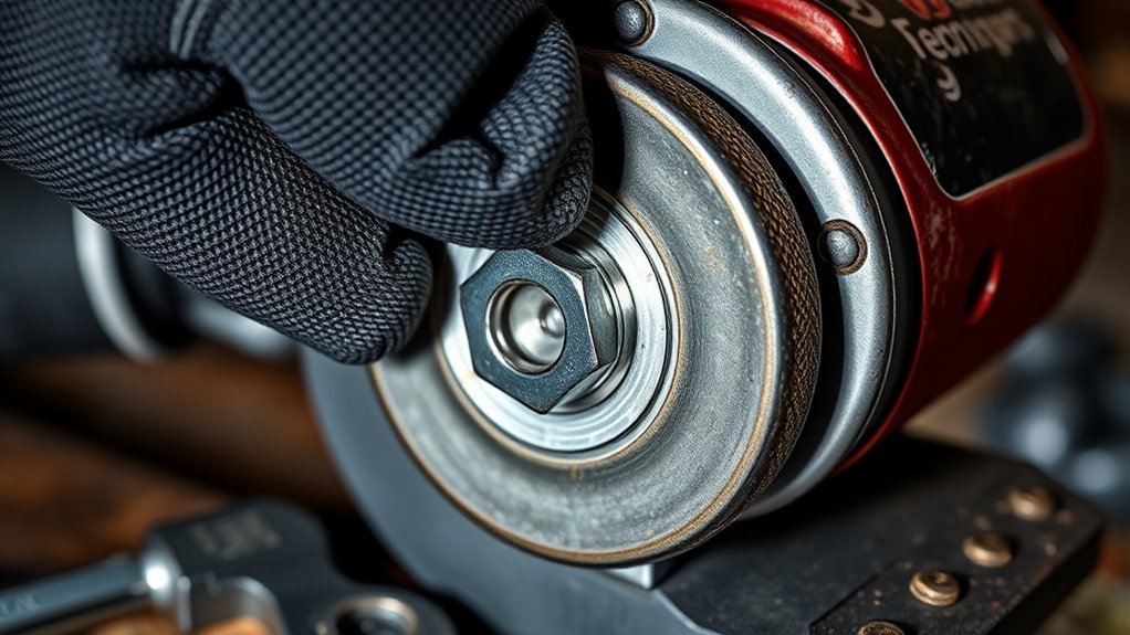
Many people search for an angle grinder “backing nut,” but most grinder manuals use more specific names. The part behind the wheel is normally the inner flange or backing flange. The removable fastener on the outside is normally called the lock nut, flange nut, or outer flange.
On a conventional threaded grinder, the normal mounting order is:
- The grinder spindle
- The inner or backing flange
- The compatible wheel or disc
- The outer lock nut or flange nut
The backing flange supports and centers the wheel, while the lock nut clamps the assembly together. OSHA requires abrasive-wheel contact surfaces and flanges to remain flat and free of foreign material. A crooked wheel, dirty flange, wrong mounting part, or damaged spindle can cause vibration, uneven loading, and wheel failure. See the OSHA requirements for portable abrasive wheels.
Note: This procedure applies to grinders with a conventional threaded spindle, backing flange, and lock nut. Tool-free mounting systems such as Bosch X-LOCK secure compatible accessories without a conventional flange nut or pin spanner.
Before You Begin
Do not install a wheel based only on its diameter. The wheel, grinder, guard, flange, and lock nut must work as one compatible system.
- Disconnect power: Unplug a corded grinder or remove the battery from a cordless model.
- Read the mounting diagram: Check the grinder manual and the instructions printed on or supplied with the accessory.
- Match the wheel diameter: Never install a wheel larger than the grinder is designed to accept.
- Check the speed rating: The wheel or attachment must have a maximum RPM rating equal to or higher than the grinder’s maximum or no-load speed. The CCOHS portable-grinder guidance explains this requirement.
- Check the arbor: The mounting hole must fit the approved flange or spindle without being forced, filed, drilled, or enlarged.
- Inspect the wheel: Do not use a wheel with cracks, chips, distortion, heavy wear, contamination, separation, or other visible damage.
- Inspect the hardware: Replace a bent flange, damaged lock nut, worn spindle thread, or defective spindle lock with an approved part.
- Clean the contact surfaces: Remove abrasive dust, metal chips, rust flakes, and grit from the flange, nut, and spindle.
- Match the guard: Use the guard required for the specific grinding, cutting, sanding, brushing, or diamond-wheel accessory.
- Install the side handle: Place it in a position that allows a firm two-handed grip.
- Use the correct wrench: Use the supplied pin spanner or the manufacturer-approved equivalent.
Warning: Never adjust the guard, press the spindle lock, install a wheel, or tighten the lock nut while power remains connected. Do not continue if the wheel, flange, nut, spindle, or guard does not match the grinder’s manual.
How to Securely Tighten the Angle Grinder Lock Nut
Follow this sequence for a conventional grinder that uses an inner flange and outer lock nut.
- Disconnect the grinder: Unplug it or remove the battery. Set the switch to the off position.
- Identify the accessory: Confirm whether you are mounting a depressed-center grinding wheel, cut-off wheel, diamond wheel, flap disc, sanding pad, or another approved accessory. Different accessories may use different hardware.
- Install the correct backing flange: Place the clean inner flange on the spindle in the orientation shown in the grinder manual. Make sure it seats fully against its locating surfaces.
- Seat the wheel: Place the wheel over the spindle or flange pilot without forcing it. The wheel should sit evenly against the supporting flange and should not rock from side to side.
- Choose the correct lock-nut orientation: Inspect both faces of the nut and follow the mounting diagram for your wheel type and thickness. Do not assume that the raised face or flat face always goes toward the wheel.
- Thread the nut by hand: Start the lock nut gently and turn it in the tightening direction specified by the manufacturer. It should engage smoothly. Stop if it binds, crosses the thread, or sits at an angle.
- Stop all spindle movement: Confirm that the spindle is completely still before pressing the spindle-lock button. The Makita XAG04 instruction manual specifically warns users to operate the shaft lock only when the spindle is not moving.
- Tighten with the supplied wrench: Hold the spindle lock and use the pin spanner to tighten the nut securely. Apply controlled hand pressure without jerking the wrench.
- Do not add leverage: Do not use a pipe extension, hammer, punch, pliers, or pipe wrench. Excessive force can damage the abrasive wheel, nut, flange, spindle, or lock mechanism.
- Release the spindle lock: Make sure the button returns to its normal position and the spindle can turn freely.
- Spin the wheel by hand: Check for scraping, rubbing, excessive runout, looseness, or contact with the guard.
- Install and position the guard: Secure the correct guard between your body and the exposed wheel before reconnecting power.
There is no single tightening torque that applies to every angle grinder, nut, and accessory. Use the torque value in your manual when one is provided. Otherwise, tighten securely with the supplied hand wrench and do not add extra leverage.
Pro Tip: If the lock nut does not thread smoothly by hand, remove it and inspect the orientation, spindle threads, flange position, and accessory compatibility. A wrench should finish a correctly started nut, not force a mismatched assembly together.
Products Worth Considering
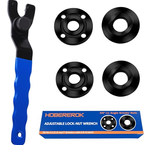
[ Universal Adjustable Angle Grinder Wrench & Nut Kit] Solve the problem of lost or missing wrenches. This versatile set includes 1 adjustable wrench that fits major brands like DeWalt, Milwaukee, and Makita, plus 4 replacement grinder flange nuts (2 inner, 2 outer). Perfect for DIY, workshops, and professional grinder parts replacement.

Replacement Part Numbers #: 224399-1, 193465-4, 224568-4 Parts. 2 adjustable locking nut wrenches , 3 sets of inner and outer corner grinding nuts. Compatible with most grinding machines and locking nuts, it is a flexible and portable household essential tool

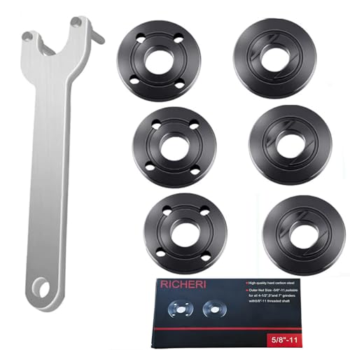
[7PCS 5/8"-11 Angle Grinder Nut Wrench Replacement Kit] 1 piece angle grinder wrench and 6 angle grinder nuts (3 inner flange nuts, 3 outer flange nuts) for lock nut removal, wheel/disc replacement.Compatible with most arbor grinders and lock nuts, Perfect for home DIY, workshop projects, and professional grinder parts replacement
Which Side of the Lock Nut Faces the Wheel?
The answer depends on the grinder, flange design, wheel type, and wheel thickness. Some two-sided nuts use one face for a thicker depressed-center grinding wheel and the other for a thin cut-off wheel. Other models use different nuts or flanges for different accessories.
Do not rely on a universal rule copied from another grinder. Use the mounting illustration in your manual and the instructions supplied with the wheel. Makita, for example, states that the direction of the lock nut and inner flange can vary with wheel thickness.
What About Threaded Grinder Accessories?
Some wire cups, backing pads, and other approved accessories screw directly onto the spindle and do not use the normal wheel-and-lock-nut stack. Install these only when the accessory thread, speed rating, guard requirements, and grinder manual all confirm compatibility.
How to Install and Position the Safety Guard
The guard helps place a barrier between you and the wheel and directs sparks, debris, and some fragments away from your body. OSHA requires guards on portable abrasive-wheel tools in normal covered applications and states that a right-angle grinder guard should be positioned between the operator and wheel.
- Select the correct guard: Use the grinding guard, cut-off guard, dust-collection guard, or other manufacturer-approved guard required for the accessory.
- Disconnect power: Never move or install the guard while the grinder can start.
- Align the mounting features: Match the guard’s tabs, grooves, clamp, or locking lever with the grinder’s guard mount.
- Lock the guard: Tighten the clamp, screw, or tool-free mechanism according to the manual.
- Position the barrier: Rotate the guard so its closed section sits between your hands and body and the wheel.
- Check clearance: Spin the wheel by hand and confirm that the guard does not touch the wheel, nut, or flange.
- Check security: The guard should not rotate or loosen under normal hand pressure.
A thin abrasive cut-off wheel may require a dedicated cut-off guard that encloses more of the wheel than a standard grinding guard. Never assume that a grinding guard is approved for every cutting operation. Never use a cut-off wheel for side grinding.
Key Safety Precautions for Operating an Angle Grinder
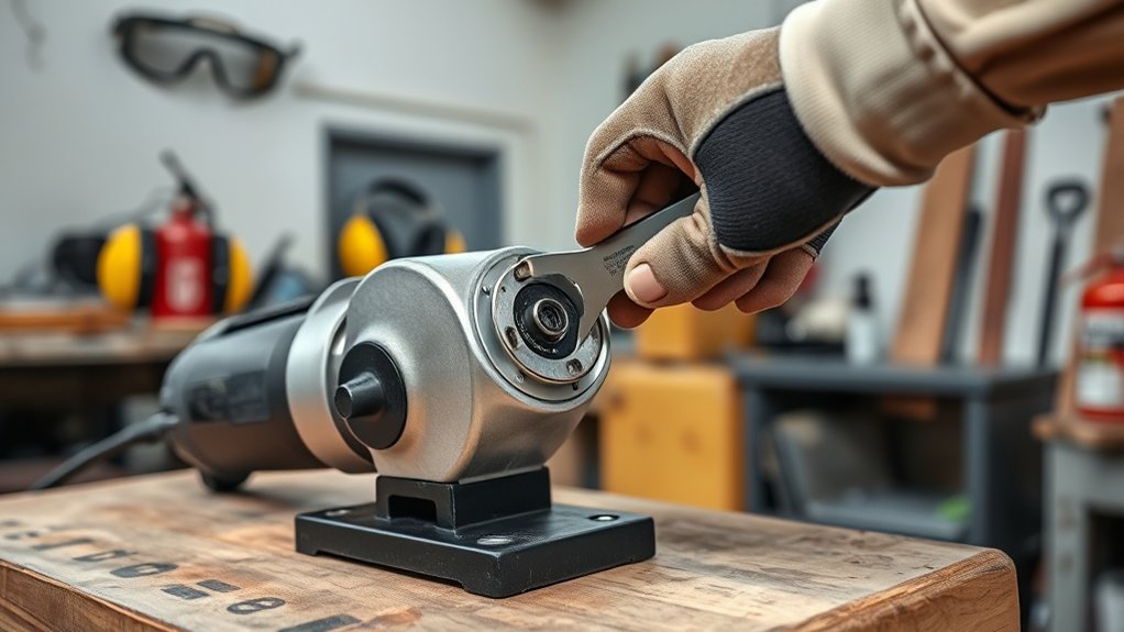
Angle grinders can produce sparks, abrasive dust, noise, sharp fragments, and kickback. Wear impact-rated safety glasses with side protection or safety goggles. Add a face shield over the eye protection when the work exposes your face to sparks or fragments. A face shield alone is not primary eye protection. OSHA’s eye and face protection standard requires suitable protection against flying particles.
Use hearing protection when noise exposure calls for it. Select respiratory protection based on the material and dust hazard rather than relying on a generic nuisance-dust mask. Keep clothing close-fitting, secure long hair, remove dangling jewelry, and use well-fitting gloves only when they do not create an entanglement risk.
Clamp or secure the workpiece. Hold the grinder with both hands, keep the side handle installed, maintain stable footing, and route the cord away from the wheel. Direct sparks away from people, vehicles, glass, gas cylinders, combustible dust, fuel, rags, and other flammable materials.
| Safety Precaution | Why It Matters |
|---|---|
| Wear safety glasses or goggles and add a face shield when needed | Protects the eyes and face from sparks, abrasive particles, and fragments |
| Use the side handle and both hands | Improves control if the wheel catches, binds, or kicks back |
| Keep the guard between you and the wheel | Helps deflect sparks, debris, and wheel fragments away from your body |
| Secure the workpiece | Prevents unexpected movement that can pinch or bind the wheel |
| Clear combustible materials | Reduces the fire and explosion risk created by sparks |
Pre-Operation Check for Safe Grinder Use
Complete this check every time you install or reinstall a grinder accessory:
- Inspect the assembly: Confirm that the backing flange, wheel, lock nut, guard, and side handle are secure and compatible.
- Check wheel clearance: Rotate the wheel by hand while the grinder remains disconnected. It should turn without touching the guard or housing.
- Check for visible runout: Watch the wheel’s edge while turning it slowly. Stop if it moves noticeably from side to side.
- Clear the area: Move people, cords, rags, fuel, dust, and loose objects away from the wheel and spark path.
- Put on protective equipment: Wear eye protection before reconnecting power.
- Take a safe position: Hold both handles and keep your face and body out of the wheel’s plane.
- Run the grinder without load: Point it away from people and let the wheel reach full speed without touching the workpiece.
- Watch and listen: Stop immediately if you notice vibration, scraping, rubbing, unusual noise, looseness, or wheel wobble.
Wait until the wheel stops completely before setting the grinder down or making another adjustment.
Troubleshooting Wheel and Lock-Nut Problems
Products Worth Considering
Replacement part numbers: 224399-1, 193465-4, 224568-4 parts Fit for Makita 9005BZ 9015B 9505BH 9527PB 9527NB 9015DB 9561CV 9016B 9049 9067L 9077SL 9564,GA7021, GA9040S 9" 15A, GA5010Z 10.5A 5", 9557NB, 9558PB, GA6020, 9005B, 9503BH, 9524NB, 9528PB, 9528NB 9" 15A Angle Grinder, etc

【INCLUDE】Our angle grinder wrench kit include 1 angle grinder wrench, 3 inner angle grinder flange nuts, 3 outer angle grinder flange nuts. We have also provided you with a storage bag for easy carrying and storage.

【Value Sets】The grinder nut set includes 1 angle grinder wrench and 6 angle grinder nuts (3 inner flange nuts, 3 outer flange nuts). Please check size and compatibility before ordering. Please contact us with any questions or concerns. We prioritize your satisfaction .
The Wheel Wobbles
Disconnect power and remove the wheel. Check for a wheel that is damaged, distorted, incorrectly seated, or incompatible with the flange pilot. Inspect the flange for dirt, burrs, bending, or incorrect orientation. Also check the spindle and lock nut for damage. Do not operate the grinder until the wheel turns true by hand and passes the no-load test.
The Lock Nut Will Not Tighten
Possible causes include a reversed or missing flange, the wrong nut, crossed spindle threads, a wheel that is too thick for the mounting system, or an accessory that requires different hardware. Do not stack washers or improvised spacers under the nut. Use only the parts listed for the grinder and accessory.
The Lock Nut Is Stuck
Disconnect power, allow the wheel to cool, and use the supplied wrench while holding the stopped spindle lock. Apply steady pressure in the removal direction shown by the manufacturer. Do not strike the wheel or nut. Do not use a torch, pipe extension, or uncontrolled impact. If the nut or spindle lock will not release normally, have the tool inspected or serviced.
The Guard Rubs the Wheel
Stop using the grinder. The guard may be misaligned, bent, loose, or incompatible with the wheel. The wheel may also be oversized or mounted incorrectly. Reinstall the correct guard and wheel according to the manual. Replace bent parts rather than bending them back into shape unless the manufacturer specifically allows adjustment.
The Spindle Lock Does Not Engage
Turn the disconnected spindle slowly by hand while gently pressing the lock until the mechanism aligns. Never press the lock while the spindle is powered or coasting. If the lock slips, jams, or does not hold, stop and arrange repair before changing the wheel.
Common Angle Grinder Nut Mistakes
Many mounting failures start with rushed setup or parts borrowed from a different grinder. Avoid these mistakes:
- Calling every mounting part a backing nut and assembling the flange and lock nut in the wrong order.
- Tightening the nut while the wheel sits crooked or rocks on the flange.
- Using a wheel with the wrong diameter, arbor size, maximum RPM, or intended application.
- Using a standard grinding guard when the accessory requires a cut-off or specialty guard.
- Using a thin cut-off wheel for side grinding.
- Forcing a wheel onto the spindle or enlarging its mounting hole.
- Using pliers, hammers, punches, pipe wrenches, or wrench extensions on the lock nut.
- Pressing the spindle lock while the spindle is moving.
- Installing a cracked, chipped, warped, contaminated, or heavily worn wheel.
- Leaving the side handle or guard off because access feels easier.
- Starting the grinder while the wheel touches the workpiece.
- Forgetting to disconnect power before changing or adjusting the wheel.
Use the exact wheel, flange, nut, guard, and installation method approved for your grinder model. The owner’s manual takes priority over general instructions when the designs differ.
Frequently Asked Questions
Which way does the angle grinder lock nut go?
Install it in the orientation shown in the grinder’s manual for the exact accessory and wheel thickness. Some two-sided lock nuts use different faces for thin cut-off wheels and thicker grinding wheels, so there is no safe universal flat-side or raised-side rule.
How tight should an angle grinder wheel be?
Tighten the lock nut securely with the supplied wrench and normal hand pressure. Use a manufacturer-listed torque value when one is provided. Do not use an extension, hammer, pipe wrench, or excessive force because over-tightening can damage the wheel and mounting parts.
What is the backing flange on an angle grinder?
The backing flange, also called the inner flange, sits behind the wheel on a conventional spindle. It supports and centers the wheel. The outer lock nut or flange nut clamps the wheel against it.
Can you use an angle grinder without the guard?
Do not remove the guard for ordinary grinding or cutting. Use the guard approved for the grinder and accessory, and position it between your body and the wheel. Some specialized operations have manufacturer-defined requirements, but removing the guard simply for convenience is unsafe.
Why does my angle grinder disc wobble?
Common causes include a damaged or distorted wheel, dirt beneath the flange, incorrect flange orientation, the wrong mounting hardware, an incompatible arbor, a bent flange, or spindle damage. Disconnect power and inspect every mounting part before operating the grinder again.
Can I tighten the lock nut without the pin spanner?
Use the supplied pin spanner, a manufacturer-approved replacement, or the tool-free mechanism designed for the grinder. Pliers and improvised tools can slip, damage the nut, or apply uneven force.
Why does the lock nut keep coming loose?
Stop using the grinder. Check for incorrect nut orientation, missing or mismatched flanges, damaged threads, a wheel that is not seated, incorrect hardware, or an accessory that should mount differently. Do not compensate by adding improvised washers or extreme tightening force.
Do all angle grinders use a backing flange and lock nut?
No. Conventional grinders commonly use an inner flange and lock nut, but tool-free systems such as X-LOCK use a different interface. Threaded brushes and backing pads may also screw directly onto an approved spindle. Follow the instructions for the exact grinder and accessory.
Safety Disclaimer: This article provides general information and does not replace the instructions from your grinder, wheel, or accessory manufacturer. Follow the manual, workplace rules, and applicable safety requirements. Stop and seek qualified service if the mounting parts are damaged, incompatible, or difficult to assemble correctly.
Conclusion
A secure angle grinder wheel depends on more than tightening one nut. Start with the correct guard, backing flange, wheel, and lock nut for the grinder. Keep every contact surface clean, follow the model-specific nut orientation, thread the nut by hand, and tighten it with the supplied wrench without extra leverage. Before working, spin the wheel by hand and run a guarded no-load test. Stop immediately if the wheel wobbles, rubs, loosens, or produces unusual vibration.
Sources
- OSHA 29 CFR 1910.243: Guarding of Portable Powered Tools — guard positioning, wheel inspection, flange surfaces, speed compatibility, and portable abrasive-wheel requirements
- OSHA 29 CFR 1910.133: Eye and Face Protection — protection against flying particles and eye hazards
- CCOHS: Use of Portable Grinders — RPM matching, PPE, two-handed control, startup positioning, and over-tightening precautions
- Makita XAG04 Angle Grinder Instruction Manual — spindle-lock use, lock-nut tightening, mounting sequence, wheel-thickness orientation, and cut-off guard requirements
- Bosch GWX10-45PE X-LOCK Angle Grinder — example of a tool-free grinder mounting system that does not use a conventional flange nut