One wrong connection can turn a useful plasma cutter into a serious shock, fire, or equipment-damage risk. A safe setup starts with the machine’s manual and nameplate, not its advertised cutting amperage. This guide explains how to check an existing 120V or 240V supply, identify a compatible plug and receptacle, and attach an approved replacement cord cap when the manufacturer permits it. New circuits, panel work, and uncertain wiring belong with a licensed electrician.
Quick Answer
To wire a plasma cutter safely, follow the exact input-voltage, circuit, plug, receptacle, and grounding requirements in its manual. Do not size the breaker from the cutter’s output amperage. Keep factory cords and adapters when possible, de-energize and verify before touching conductors, and use a licensed electrician for panel or new-circuit work.
Key Takeaways
- Read the plasma cutter’s manual and input nameplate before choosing a plug, breaker, receptacle, or conductor size.
- The amperage advertised for cutting output is not the same as the current drawn from the branch circuit.
- Use the factory power cord and approved voltage adapter whenever the manufacturer supplies them.
- A work clamp completes the cutting circuit. It does not replace the equipment grounding conductor.
- Never install a larger breaker merely to stop repeated trips.
- Hire a licensed electrician for a new circuit, service-panel work, uncertain conductor identification, or live electrical testing.
At a Glance
| Time Required | About 20 to 45 minutes for inspection or an approved replacement cord cap; longer for a new circuit |
| Difficulty | Intermediate for a manufacturer-approved replacement plug; professional for branch-circuit or panel work |
| Tools Needed | Manual, approved plug or adapter, screwdriver, wire stripper, suitable tester, and strain relief |
| Cost | Low for an approved replacement plug; variable for a permitted dedicated circuit installed by an electrician |
What’s in This Article
- Before You Begin
- Read the Manual and Nameplate
- What You’ll Need
- Understanding 120V Wiring Configurations
- Setting Up 240V Connections
- Choosing the Right Breaker, Wire, and Receptacle
- GFCI, Dedicated Circuit, and Shared Loads
- Using an Extension Cord Safely
- Ensuring Proper Strain Relief and Wire Connections
- Adhering to Local Electrical Codes and Standards
- Testing the Connection Safely
- Troubleshooting Common Wiring Issues
- Common Mistakes to Avoid
- Frequently Asked Questions
- Conclusion
Before You Begin
Estimated total time: A visual inspection or manufacturer-approved replacement plug may take about 20 to 45 minutes. Installing a new dedicated circuit can take much longer and may require a permit, inspection, and licensed electrician.
First, decide what type of work your plasma cutter actually needs. A dual-voltage machine may already have a factory cord and approved 120V or 240V adapter. In that case, changing the plug or opening the machine can create a problem instead of solving one.
Decide Whether You Should Wire Anything
- Factory cord and correct outlet: Do not alter the wiring. Inspect the cord and use it as directed.
- Factory voltage adapter supplied: Use only the approved adapter and follow the manual.
- Damaged replaceable plug: Install the exact approved replacement only if the manufacturer permits field replacement.
- Wrong receptacle or inadequate circuit: Have an electrician assess or install the circuit.
- Missing manual or unclear wire identification: Stop and obtain the correct manual or professional help.
Warning: A switched-off breaker does not make every part of a service panel safe. Line-side components may remain energized. Do not remove a panel cover, install a breaker, or work on exposed energized conductors unless you are qualified and equipped for that work.
Before touching conductors, disconnect the machine, shut off the applicable circuit, prevent accidental re-energization where practical, and verify the de-energized condition with suitable test equipment. OSHA’s electrical safe-work requirements explain why verification is necessary before exposed parts are treated as de-energized.
Read the Manual and Nameplate
The manual and machine nameplate control the setup. Do not choose a circuit from the cutter’s model name, maximum cutting output, or a recommendation for another machine.
| Specification | What It Tells You |
|---|---|
| Input voltage | The supply voltage the machine accepts, such as 120V, 240V, or an automatic dual-voltage range. |
| Phase and frequency | Whether the machine needs single-phase or three-phase power and the supported frequency. |
| Input current | The current the machine draws from the supply under stated conditions. |
| Output current | The adjustable cutting current delivered by the plasma power supply. It is not the branch-circuit current. |
| Duty cycle | How long the cutter can operate at a stated output and temperature before it must cool. |
| Recommended protection | The manufacturer’s fuse, breaker, or branch-circuit guidance for that exact model. |
| Plug or cord specification | The approved connection method, conductor count, plug style, and adapter limitations. |
Output amperage is not branch-circuit amperage. For example, one dual-voltage 30 A plasma cutter lists 29 A input at 120 V and 15 A input at 240 V. Always use the figures for your exact machine, not a generic chart.
You can see that model-specific difference in Hypertherm’s official Powermax30 AIR specifications.
What You’ll Need
The exact parts depend on the plasma cutter, cord, circuit, and locally adopted code. For an inspection or approved replacement cord cap, gather:
- The manual for the exact plasma cutter model
- The machine nameplate and factory wiring diagram
- A manufacturer-approved plug, receptacle, or factory adapter
- A strain-relief fitting sized for the cord and plug body
- The correct screwdriver or torque tool specified by the device maker
- A wire stripper suitable for the conductor size
- An appropriate multimeter, receptacle tester, or voltage tester
- Safety glasses for protection from clipped wire strands and small parts
- Good lighting and a clean, dry work area
Do not rely on ordinary work gloves as protection from energized conductors. De-energize the circuit. Electrical testing or work that exposes live parts requires a qualified person, appropriate procedures, and correctly rated protective equipment.
Products Worth Considering

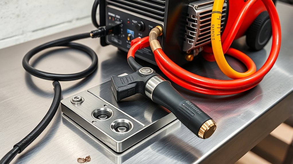
【Welder Adapter Cord】Suplevel 10-50P to 6-50R Welder Adapter connects a welder, plasma cutter, or electric vehicle to a 4-prong Dryer outlet; supports up to 50 amps...
Understanding 120V Wiring Configurations
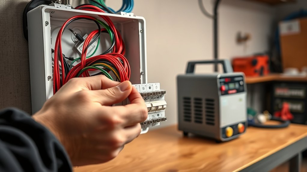
A 120V plasma cutter may use a standard NEMA 5-15 plug, a NEMA 5-20 plug, or a manufacturer-specific factory connection. A 5-20 plug must not be forced into or adapted to a 5-15 receptacle. The circuit, receptacle, plug, cord, and machine must all be compatible.
Some dual-voltage cutters reduce their maximum cutting output or duty cycle on 120V. Others draw more current than a general-purpose household circuit can provide. “Runs on 120V” does not automatically mean “works at full output on any household outlet.”
Wiring an Approved 120V Replacement Plug
Use these steps only for a replaceable cord cap when the plasma cutter manufacturer permits the repair. Follow the plug maker’s strip-length and torque instructions.
- Unplug the machine and confirm that the cord is fully disconnected from power.
- Inspect the full cord. Replace the cord or obtain professional service if the jacket is cut, burned, brittle, crushed, or repaired with tape.
- Slide the plug housing and strain-relief parts onto the cord in the correct order.
- Strip only the amount of jacket and conductor insulation specified by the plug manufacturer.
- For a conventional U.S. 120V cord, connect the identified hot conductor, commonly black, to the brass or marked hot terminal.
- Connect the identified neutral conductor, commonly white, to the silver or marked neutral terminal.
- Connect the green or green-and-yellow grounding conductor to the green grounding terminal.
- Keep all copper strands under the terminal clamp. Do not leave exposed copper outside the terminal.
- Tighten each terminal to the device maker’s specified torque.
- Clamp the strain relief around the outer cord jacket, not around individual conductors.
- Close the plug body and perform a gentle tug test before the connection is inspected and tested.
Note: Terminal markings and the manufacturer’s wiring diagram take priority over assumed wire colors. Stop if the cord contains unexpected colors, damaged conductors, or an unclear arrangement.
Setting Up 240V Connections

A 240V single-phase plasma cutter commonly uses two ungrounded hot conductors and one equipment grounding conductor. Many such machines do not use a neutral, but the exact cord, plug, and circuit must follow the machine diagram.
A NEMA 6-50R, for example, is a 50 A, 250 V, two-pole, three-wire grounding receptacle. That description does not mean every plasma cutter should use one. Other machines may use a 6-30 connection, a different factory plug, a hardwired disconnect, or an approved adapter.
| Connection | Typical Description | Important Limit |
|---|---|---|
| NEMA 5-15 | 125V, 15 A grounding connection | Use only when the machine and circuit are approved for it. |
| NEMA 5-20 | 125V, 20 A grounding connection | Requires a compatible 20 A configuration and circuit. |
| NEMA 6-30 | 250V, 30 A, two-pole grounding connection | No neutral; use only when specified. |
| NEMA 6-50 | 250V, 50 A, two-pole grounding connection | The receptacle rating does not determine the machine’s required circuit. |
| NEMA 14-50 | 125/250V, 50 A, two hots, neutral, and ground | Do not make a homemade adapter or omit required conductors. |
Wiring an Approved 240V Replacement Plug
Only attach a replacement 240V plug when the machine manufacturer permits it and the plug matches the cord, voltage, conductor count, and circuit.
- Disconnect the power cord completely from the supply.
- Confirm the replacement plug configuration in the plasma cutter manual.
- Inspect the full cord for heat, cuts, crushed sections, repairs, or exposed conductors.
- Connect each identified hot conductor to one of the marked hot terminals.
- Connect the equipment grounding conductor only to the grounding terminal.
- Do not connect neutral and ground together in the plug.
- Do not use the grounding conductor as a current-carrying conductor.
- Tighten each connection to the plug manufacturer’s torque specification.
- Secure the cord jacket in the strain relief and close the housing.
- Have the completed connection inspected and tested before use.
A white conductor may be re-identified for use as an ungrounded conductor in certain code-compliant cable installations, but that does not make guessing safe. If conductor identification is unclear, stop and call an electrician.
Choosing the Right Breaker, Wire, and Receptacle
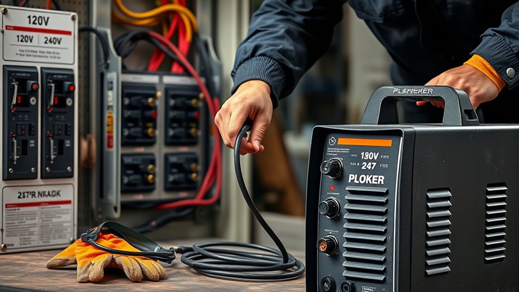
A breaker protects the branch-circuit wiring. It is not a performance adjustment for the plasma cutter. Breaker size, conductor ampacity, receptacle rating, plug configuration, circuit length, terminal ratings, installation method, and manufacturer instructions must work together.
Do not select a breaker from the cutter’s output setting. A machine labeled as a 30 A, 40 A, or 50 A plasma cutter is describing cutting output, not necessarily its wall-current requirement.
Use this process:
- Find the input voltage, phase, input current, and recommended branch protection in the manual.
- Confirm whether the manufacturer requires a dedicated circuit.
- Identify the plug and receptacle configuration approved for the machine.
- Have the conductor size checked against the breaker, run length, wiring method, terminal temperature ratings, and locally adopted code.
- Confirm that every component is listed and rated for the actual voltage and current.
- Replace any breaker, receptacle, cord, or plug showing heat discoloration, cracking, loose contact, or melted material.
Do not increase breaker size to stop nuisance trips unless a qualified electrician has confirmed that the conductors, receptacle, equipment instructions, and installation all permit the change. OSHA also prohibits increasing circuit protection beyond the load rating of existing wiring.
Pro Tip: Photograph the machine nameplate and save the manual on your phone. You can then show the exact input specifications to an electrician or parts supplier without relying on the cutter’s model nickname.
Products Worth Considering

【Flush Mount Power Outlet】 The flush mount receptacle features a heavy gauge galvanized steel mounting strap for corrosion resistance. It fits in BOTH single and 2-Gang box styles. Flush receptacles are completely ready-to-wire, which significantly shortens installation time.

SPECIFICATIONS: Features 2 pole, 3 wire, 250 volt, 50 amp surface mount Nema 6-50 outlet.

50 Amp Welder Adapter: our welder power adapter helps you connect welding machines or plasma cutters to stove, oven, dryer or other 10-50 power socket; Connect 10-50P plug to 3 prong 50amp outlet, and connect 6-50R receptacle to 3 prong welder plug; Support max 50 Amp overload, 250V, max wattage 12500 watts
GFCI, Dedicated Circuit, and Shared Loads
GFCI Protection
Garages, outdoor work areas, damp locations, and other shop environments may require ground-fault circuit-interrupter protection under the electrical code adopted in your area. Exact requirements depend on location, voltage, circuit rating, equipment type, and local amendments.
A GFCI detects an unintended difference between outgoing and returning current and disconnects power quickly. It does not replace the equipment grounding conductor or the branch-circuit breaker.
If a plasma cutter trips a required GFCI, do not bypass the GFCI or replace it with an unprotected connection. Check the machine, cord, plug, receptacle, moisture exposure, extension cord, and circuit for faults. A qualified electrician or authorized service center may need to test the equipment.
Dedicated Circuit
Use a dedicated circuit when the plasma cutter manual requires one or when other loads would exceed the circuit’s capacity. A dedicated circuit also reduces voltage drop and unexpected trips caused by tools starting at the same time.
An external air compressor can be a substantial second load. Do not assume the cutter and compressor can share one circuit merely because each runs successfully by itself. Compressor motor starting current can trip the breaker or pull the voltage down while the plasma arc is active.
Work Clamp Versus Equipment Ground
The plasma cutter’s work clamp is part of the cutting-current return path. It helps complete the arc circuit through the workpiece. It is not the same as the equipment grounding conductor in the power cord.
Never remove the plug’s grounding pin or rely on the work clamp to ground the cutter’s enclosure. The receptacle grounding contact must connect to the branch circuit’s equipment grounding conductor.
Using an Extension Cord Safely
Use an extension cord only when the plasma cutter manual allows one. The cord must have the correct voltage, conductor count, ampacity, insulation, temperature, and environmental rating for the machine and work area.
Follow these rules:
- Use a listed grounding-type cord with an intact grounding path.
- Follow the manufacturer’s minimum conductor-size table for the cord length.
- Keep the cord as short as practical to reduce voltage drop.
- Do not daisy-chain extension cords.
- Do not use a light-duty household cord for a high-input plasma cutter.
- Do not use a homemade voltage adapter.
- Protect the cord from sparks, sharp metal, water, vehicle traffic, doors, and hot surfaces.
- Uncoil the cord so heat cannot build up in a tight bundle.
- Inspect the plug, connector, grounding pin, jacket, and strain relief before use.
- Remove damaged cords from service rather than covering damaged insulation with tape.
OSHA’s flexible-cord guidance emphasizes grounding and protection from damage. A cord that becomes warm, causes weak arc starts, or repeatedly trips protection may be undersized, too long, damaged, or connected to an inadequate circuit.
Ensuring Proper Strain Relief and Wire Connections
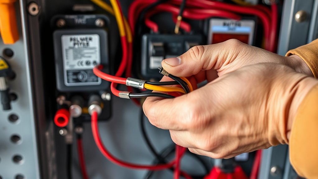
Strain relief prevents cord movement from pulling directly on the plug terminals. It must grip the outer jacket rather than the insulated conductors or bare copper.
Secure Cable Strain Relief
Check these points before closing the plug:
- The clamp matches the cord diameter.
- The clamp grips the outer jacket firmly.
- No bare conductor sits under the clamp.
- The cord does not make a sharp bend where it enters the plug.
- The cable jacket extends far enough into the housing to protect the conductors.
- A gentle tug on the cord does not move the internal wires.
- The plug housing closes without pinching insulation.
Tighten Wire Connection Screws
A loose terminal creates resistance. Under a heavy load, that resistance can produce heat, arcing, voltage loss, melted insulation, and intermittent operation.
Use the torque value printed on the plug, included with its instructions, or listed by the manufacturer. “As tight as possible” is not a safe substitute. Overtightening can damage the terminal or conductor, while undertightening can allow movement and heat.
Keep all conductor strands together and fully under the terminal plate or clamp. Do not tin stranded conductors with solder unless the device manufacturer specifically permits it, because solder can creep under pressure and loosen the connection.
Inspect portable equipment regularly if you move it around the shop. Recheck the plug, strain relief, cord jacket, and receptacle if the connection becomes hot, loose, discolored, or unreliable.
Adhering to Local Electrical Codes and Standards
In the United States, NFPA 70, the National Electrical Code, provides installation requirements for residential, commercial, and industrial electrical systems. The 2026 NEC is the current edition, but your state, city, or county may enforce an earlier edition or local amendments.
Check the NFPA NEC enforcement information and contact your local authority having jurisdiction before installing a new circuit. A permit and inspection may be required.
- Wire selection: Match conductor ampacity and type to the breaker, terminals, wiring method, environment, and run length.
- Overcurrent protection: Use protection allowed by the manufacturer and adopted code.
- Dedicated circuit: Provide one when required by the manual or load calculation.
- Grounding: Maintain a continuous equipment-grounding path from the receptacle to the supply system.
- GFCI or other protection: Install required protective devices for the location and circuit.
- Listing and labeling: Use approved plugs, receptacles, enclosures, fittings, cords, and breakers.
- Inspection: Complete required inspection before regular use.
NEMA plug descriptions and NEC rules are U.S.-focused. In Canada or another country, use the machine version, voltage system, plug standard, electrical code, and qualified trade requirements that apply in that location.
Testing the Connection Safely
Testing should confirm that the supply and connection are correct without exposing an unqualified person to energized parts.
Before Energizing
- Confirm that the plug body is fully closed.
- Check that the strain relief grips the outer jacket.
- Make sure no copper is exposed outside a terminal.
- Verify that the grounding conductor is connected to the grounding terminal.
- Confirm that the plug matches the receptacle without an improvised adapter.
- Inspect the receptacle for cracks, looseness, discoloration, or heat damage.
- Confirm that the cutter’s voltage selector, if it has one, is set correctly while disconnected.
Electrical Verification
A qualified person can verify receptacle voltage, conductor arrangement, grounding continuity, and polarity with suitable test equipment. Do not remove a live panel cover or probe exposed internal terminals merely to complete a home test.
After the connection passes inspection:
- Set the cutter to its lowest appropriate output.
- Connect clean, dry air at the pressure and flow required by the manual.
- Attach the work clamp to clean metal on the workpiece or cutting table.
- Energize the circuit and watch for an immediate fault, unusual sound, smell, or display error.
- Perform a brief test cut on suitable scrap metal.
- Switch off and unplug the machine before checking the plug and receptacle for looseness or unusual heat.
Stop immediately if you notice smoke, arcing, a burning smell, melted material, repeated trips, tingling from the enclosure, or a hot plug.
Troubleshooting Common Wiring Issues
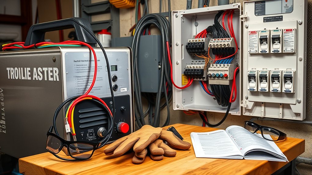
Start troubleshooting with the machine disconnected and the circuit safely de-energized. Check the manual’s error codes before changing any electrical part.
| Symptom | Possible Causes | Safe Next Step |
|---|---|---|
| Cutter will not power on | No supply voltage, open disconnect, wrong adapter, damaged cord, loose plug, or machine fault | Disconnect the cutter, inspect visible parts, verify the supply through a qualified person, and check the manual’s fault indicators. |
| Breaker trips immediately | Short circuit, incorrect wiring, damaged cord, internal machine fault, or incompatible supply | Stop resetting the breaker. Disconnect the machine and obtain professional testing. |
| Breaker trips while cutting | Overloaded circuit, shared compressor load, voltage drop, undersized extension cord, loose connection, or wrong circuit | Compare the complete setup with the manual and have the circuit capacity and connections checked. |
| GFCI trips | Ground leakage, moisture, damaged insulation, faulty extension cord, wiring error, or machine fault | Do not bypass the GFCI. Dry and inspect the setup, then arrange qualified testing if the trip repeats. |
| Weak or unstable arc | Low supply voltage, excessive cord length, loose plug contact, poor work-clamp contact, air problem, or worn consumables | Check supply and cord requirements, clean the clamp point, verify air, and inspect consumables. |
| Plug or receptacle becomes hot | Loose terminal, worn contact, corrosion, damaged receptacle, overload, or undersized component | Stop using the cutter. De-energize the circuit and replace or repair the damaged connection through a qualified person. |
Identifying Loose Connections
Loose connections can cause flickering displays, weak arc starts, heat, discoloration, crackling sounds, or breaker trips. Inspect only while the machine is disconnected and the applicable circuit is safely de-energized.
- Inspect visually: Look for cracked housings, missing pins, damaged insulation, heat marks, or melted material.
- Perform a gentle tug test: Confirm that the cord jacket stays secure in the strain relief.
- Check terminal torque: Follow the device manufacturer’s specification rather than guessing.
- Check grounding continuity: Have a qualified person verify the intended grounding path.
- Remove damaged parts: Do not continue using a burned plug or loose receptacle.
Resolving Incorrect Wiring
Incorrect wiring can prevent startup, energize exposed metal, damage the cutter, or create a short circuit. Review the exact machine and plug diagrams before moving any conductor.
For a conventional 120V U.S. connection, the identified hot, neutral, and grounding conductors must reach their respective marked terminals. For a typical 240V NEMA 6-series connection, the two hot conductors and equipment ground must reach the correct terminals without using a neutral.
Stop and call a qualified electrician if you find:
- Neutral and ground joined inside the plug
- A grounding pin that has been removed
- Unidentified or re-marked conductors you cannot verify
- Melted insulation or carbon tracking
- A receptacle that does not match the machine’s approved plug
- A homemade adapter or altered factory cord
- Repeated breaker or GFCI trips
- Voltage present where the machine manual does not expect it
Pro Tip: Label the plasma cutter circuit with its voltage and intended receptacle after installation. Clear labeling reduces the chance that someone connects incompatible equipment or shuts off the wrong circuit during maintenance.
Common Mistakes to Avoid
Most plasma cutter wiring failures begin with a shortcut. Avoid these common mistakes:
- Sizing the circuit from the plasma cutter’s output amperage
- Installing a larger breaker without verifying every other circuit component
- Assuming every dual-voltage cutter reaches full output on 120V
- Replacing a factory adapter with a homemade adapter
- Using neutral and equipment ground interchangeably
- Removing the grounding pin from a plug
- Assuming the work clamp grounds the machine enclosure
- Using an undersized or excessively long extension cord
- Running the plasma cutter and air compressor on an overloaded shared circuit
- Clamping strain relief onto individual wires instead of the cord jacket
- Leaving exposed copper outside a terminal
- Ignoring a warm plug, loose receptacle, burning smell, or repeated trip
- Working inside an energized service panel without the required qualifications
A repeated trip is a warning that the circuit or equipment needs inspection. Do not keep resetting the protective device until you find and correct the cause.
Frequently Asked Questions
Can I use an extension cord with a plasma cutter?
Yes, but only when the plasma cutter manual permits it. Use a listed grounding cord with the correct voltage, conductor count, ampacity, insulation, and minimum wire size for its length. Keep it short, protect it from damage, and never daisy-chain cords or use a homemade voltage adapter.
What personal protective equipment is necessary when wiring a plasma cutter?
For de-energized plug inspection, safety glasses protect against clipped wire strands and small parts. Ordinary work gloves do not make energized work safe. Only qualified people should work on exposed live parts, using the procedures, tools, and voltage-rated protective equipment required for that task.
How do I determine the correct wire gauge for my plasma cutter?
Start with the input-current and branch-circuit instructions for the exact machine. The final conductor size also depends on the breaker, circuit length, wiring method, terminal ratings, ambient conditions, and locally adopted code. Do not select wire size from the cutter’s output amperage alone.
How can I safely test whether the wiring is correct?
Inspect the disconnected cord, terminals, plug housing, grounding connection, and strain relief first. A qualified person can then verify receptacle voltage, conductor arrangement, polarity where applicable, and grounding continuity with suitable test equipment. Do not open an energized panel or probe exposed live parts without the required training.
What should I do if my plasma cutter frequently trips the breaker?
Stop using it until you identify the cause. Possible causes include an overloaded or shared circuit, wrong supply voltage, an undersized extension cord, loose connections, damaged wiring, a short circuit, or an internal machine fault. Do not install a larger breaker without a complete circuit assessment.
Can I plug a plasma cutter into a dryer or range outlet?
Only when the plasma cutter manufacturer approves that exact supply and connection method. Dryer and range receptacles may have different voltage, neutral, grounding, and circuit configurations. Do not make a homemade adapter, combine neutral and ground, or assume that a physically compatible connection is electrically correct.
Does the plasma cutter work clamp ground the machine?
No. The work clamp provides the return path for cutting current through the workpiece. The equipment grounding conductor in the power cord and branch circuit provides the protective grounding path for the machine enclosure. You need both connections in their intended roles.
Electrical Safety Disclaimer: This article provides general information and does not replace the plasma cutter manual, locally adopted electrical code, inspection requirements, or professional electrical advice. Use a licensed electrician for new circuits, panel work, uncertain wiring, or any task involving exposed energized parts.
Conclusion
Safe plasma cutter wiring begins with the exact machine manual, input nameplate, and locally approved circuit. Keep the factory cord and adapter whenever possible. If you replace an approved plug, identify every conductor, use the correct terminals and torque, secure the cord jacket with proper strain relief, and inspect the completed connection before energizing it.
Do not size a breaker from cutting-output amperage, substitute a work clamp for equipment grounding, bypass a required GFCI, or keep resetting a tripping breaker. When the job involves a new receptacle, branch circuit, service panel, unclear conductors, or live testing, a licensed electrician is the safer choice.
Sources
- NFPA 70, National Electrical Code and the NEC enforcement maps — current NEC information and local adoption context
- OSHA 1910.333: Selection and Use of Work Practices — de-energization, verification, and qualified-person requirements
- OSHA Flexible-Cord Safety and OSHA 1910.334 — extension-cord grounding, inspection, and removal of damaged equipment
- OSHA 1910.304: Wiring Design and Protection — receptacle grounding and equipment-grounding requirements
- Hypertherm Powermax30 AIR Documentation — manufacturer example of dual-voltage input current and duty-cycle differences
- Leviton NEMA 6-50R Specifications — official voltage, amperage, pole, wire, and grounding configuration