
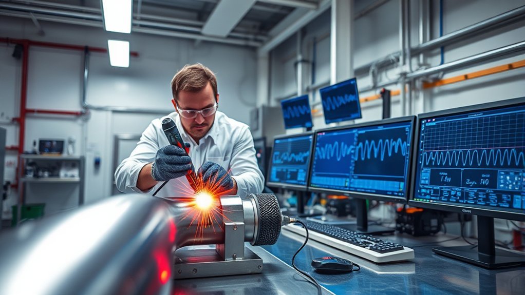
Non-destructive weld testing helps you examine weld quality without cutting, bending, or breaking the finished part. The main methods are visual testing, liquid penetrant testing, magnetic particle testing, ultrasonic testing, and radiographic testing. Each method responds to different conditions, so the right choice depends on the material, likely discontinuity, joint design, access, surface condition, safety requirements, and governing inspection code.
Quick Answer
Start weld inspection with visual testing. Use penetrant testing for surface openings in clean, nonporous materials and magnetic particle testing for surface or near-surface flaws in ferromagnetic metals. Ultrasonic and radiographic testing examine internal conditions. The governing code, material, geometry, access, and expected flaw type determine the final method.
Key Takeaways
- No NDT method detects every type, size, depth, and orientation of weld discontinuity.
- Visual testing, liquid penetrant testing, and magnetic particle testing mainly examine surface or near-surface conditions.
- Ultrasonic testing and radiographic testing can examine internal weld conditions, but they respond differently to flaw shape and orientation.
- An indication is not automatically a rejectable defect. It must be evaluated against the applicable acceptance criteria.
- Code-required NDT must use qualified personnel, an approved procedure, suitable equipment, documented calibration, and traceable reporting.
Why Non-Destructive Testing Matters for Weld Integrity

Non-destructive testing, commonly shortened to NDT, uses inspection methods that evaluate materials, components, and welds without making the part unusable. The related terms non-destructive examination, or NDE, and non-destructive inspection, or NDI, are also used in different industries.
NDT can reveal or help characterize cracks, porosity, inclusions, incomplete penetration, lack of fusion, undercut, dimensional problems, surface openings, corrosion, and other material or welding discontinuities. Finding these conditions before a component enters service can reduce repair costs, improve traceability, and lower the risk of an unexpected failure.
Weld NDT is especially important in pressure equipment, pipelines, structural steel, aerospace parts, vehicles, cranes, tanks, ships, and power-generation equipment. The inspection scope in these applications normally comes from a drawing, contract, welding code, owner specification, quality plan, or regulatory requirement.
Indications, Discontinuities, and Defects Are Not the Same
An indication is the response produced by an inspection method. A magnetic-particle buildup, penetrant bleed-out, ultrasonic echo, or dark radiographic area is an indication. The inspector must decide whether that response is relevant, nonrelevant, or false.
A discontinuity is an interruption in the normal structure or shape of the weld or base material. A discontinuity becomes a defect only when its type, size, location, or number exceeds the acceptance criteria for the job.
NDT produces information. The governing code, specification, and responsible inspector determine whether the weld is acceptable.
Note: NDT does not automatically pass or reject a weld. It detects and records indications. Those indications must be evaluated against the project drawing, inspection procedure, code, and acceptance standard.
Common NDT Methods Used in Weld Testing
The five methods most often discussed for general weld inspection are visual testing, liquid penetrant testing, magnetic particle testing, ultrasonic testing, and radiographic testing. The AWS guide for non-destructive examination of welds also covers electromagnetic and leak-testing methods because some weldments require more specialized inspection.
| Method | Best Starting Uses | Main Limits |
|---|---|---|
| Visual Testing (VT) | Fit-up, joint preparation, bead profile, weld size, undercut, overlap, alignment, visible cracks, and surface condition | Needs adequate access, lighting, cleanliness, and line of sight; cannot establish internal soundness |
| Liquid Penetrant Testing (PT) | Fine surface-breaking discontinuities in clean, solid, nonporous materials | Only finds openings connected to the surface; contamination, coatings, porosity, and smeared metal can hide or confuse indications |
| Magnetic Particle Testing (MT) | Surface and near-surface discontinuities in ferromagnetic materials, especially carbon and many low-alloy steels | Only works when the exact material can be magnetized; field direction, coatings, geometry, and residual magnetism affect results |
| Ultrasonic Testing (UT) | Internal cracks, lack of fusion, incomplete penetration, laminations, thickness checks, and other reflective discontinuities | Requires calibration, trained interpretation, suitable sound paths, and adequate scanning surfaces; grain structure and geometry can complicate results |
| Radiographic Testing (RT) | Internal porosity, slag, voids, inclusions, profile changes, and a lasting film or digital image record | Uses ionizing radiation, normally requires source and detector access, and may miss tight planar flaws aligned poorly with the beam |
Surface, Volumetric, and Specialized Methods
VT and PT are surface methods. MT is primarily a surface and near-surface method. UT and RT are commonly described as volumetric methods because they examine conditions inside the material. That classification is useful, but it does not mean that UT and RT have equal sensitivity to every internal discontinuity.
Planar discontinuities, such as cracks and lack of fusion, often respond strongly to UT when the sound beam reaches them at a useful angle. Volumetric discontinuities, such as rounded porosity and some slag inclusions, may be easier to recognize radiographically. Actual performance still depends on the procedure, equipment, thickness, geometry, orientation, and technician.
How to Plan an NDT Weld Inspection
A reliable inspection starts with a written requirement, not with choosing whichever instrument is available. Use the following sequence to build the inspection plan.
- Identify the governing requirements. Confirm the applicable code, drawing, customer specification, inspection extent, hold points, acceptance criteria, and required records.
- Define the inspection purpose. Decide whether the job concerns fit-up, final workmanship, surface cracking, internal weld quality, corrosion, leak tightness, or an in-service damage mechanism.
- Identify likely discontinuities. Consider the welding process, joint type, material, thickness, restraint, heat input, service history, and known failure modes.
- Check material compatibility. Confirm magnetizability for MT, porosity and chemical compatibility for PT, sound transmission for UT, and radiographic penetrability and access for RT.
- Review geometry and access. Determine whether the inspector can see the weld, position a probe, scan the required volume, place a detector, or reach both sides of the joint.
- Set preparation requirements. Define cleaning, coating removal, weld-cap condition, surface temperature, lighting, couplant, and any post-inspection cleaning or demagnetization.
- Use an approved procedure. The procedure should define equipment, calibration, sensitivity, technique, coverage, evaluation, recording, and reporting requirements.
- Assign qualified personnel. Confirm method, level, sector, employer authorization, vision requirements, and any code-specific qualification.
Warning: A home penetrant kit or magnetic yoke does not replace code-required inspection. Production, structural, pressure, pipeline, aerospace, lifting, and other safety-critical welds must be examined under the required procedure by appropriately qualified and authorized personnel.
Products Worth Considering
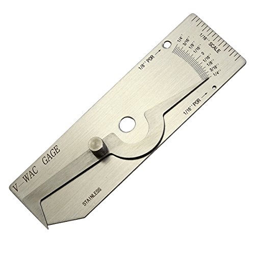
V-WAC Single Weld Gage


10 LB LIFTING FORCE – Delivers over 4.5 kg / 10 lb AC lifting force for reliable magnetic particle inspection of ferromagnetic parts.
When Weld NDT Is Performed
Weld inspection is not limited to the finished bead. Many costly problems can be prevented by checking the joint before and during welding.
Before Welding
- Confirm material identity, thickness, joint design, bevel angle, root opening, backing, alignment, and cleanliness.
- Check consumables, tack welds, temporary attachments, preheat requirements, and access for later inspection.
- Verify that the welding procedure and welder qualification match the work.
During Welding
- Monitor interpass cleaning, bead placement, interpass temperature, distortion, arc strikes, and visible cracking.
- Inspect roots or intermediate layers when the completed joint will hide them.
- Confirm that repairs follow the approved repair procedure and receive any required reinspection.
After Welding and In Service
- Perform final VT after the weld is cool enough and the surface is ready for examination.
- Apply the specified surface or volumetric methods at the required inspection stage.
- For delayed-cracking risks, observe any required waiting period before final examination.
- During service, select methods based on expected fatigue cracks, corrosion, erosion, creep, hydrogen damage, or other operating damage.
Visual Testing (VT): The First Weld Inspection Step
Visual testing is usually the first NDT method applied to a weld. It may use direct viewing, magnifiers, mirrors, weld gauges, flashlights, cameras, borescopes, or video scopes.
VT can check weld size, bead contour, undercut, overlap, excessive reinforcement, arc strikes, crater condition, spatter, visible surface porosity, alignment, root condition, and general workmanship. Dimensional gauges can also verify fillet-weld size, groove-weld reinforcement, undercut depth, and joint misalignment where the governing procedure permits.
For many jobs, VT takes place before welding, during welding, and after welding. Pre-weld checks can catch poor fit-up, incorrect joint preparation, contamination, and weak tack welds before those conditions become hidden or expensive to repair.
VT remains limited by access, lighting, surface cleanliness, viewing angle, visual acuity, and inspector judgment. A weld that looks smooth can still contain internal lack of fusion, incomplete penetration, slag, porosity, or cracking.
Radiographic Testing (RT) for Internal Weld Flaws
Radiographic testing uses X-rays or gamma rays to create an image based on differences in material thickness and radiation absorption. Radiation passes through the part to film, a computed-radiography plate, or a digital detector. Changes in density, thickness, void content, and internal geometry appear as image variations.
RT is useful when the inspection requires a lasting visual record or strong sensitivity to volumetric conditions such as porosity, slag, voids, inclusions, and some incomplete-penetration profiles. It is used on pipe welds, pressure vessels, tanks, castings, structural components, and other critical fabrications when the code and geometry permit it.
Warning: Radiographic testing uses ionizing radiation. Only trained and authorized personnel should perform it using the required licenses, exposure controls, barriers, surveys, monitoring devices, warning systems, and site procedures. Never enter a controlled radiography area unless the responsible radiation-safety personnel have released it.
RT has important limits. Conventional setups normally require access for a radiation source on one side and an image receptor on the other. Complex geometry, large thickness, restricted access, scatter, image unsharpness, exposure time, and radiation controls can increase cost and setup time.
Defect orientation also matters. A tight crack or lack-of-fusion plane can produce little thickness change along the radiation beam and may be difficult to see. For that reason, UT may be a better starting method for some planar discontinuities.
Ultrasonic Testing (UT): Techniques and Benefits

Ultrasonic testing sends high-frequency sound into a weld or base material and analyzes the returning signals. A transducer introduces sound into the part, usually through a liquid or gel called couplant. Echoes can return from the back wall, material boundaries, geometric features, or discontinuities.
UT is widely used because it can examine internal conditions without ionizing radiation and can often be performed from one accessible side. With a suitable procedure, calibration, and scan plan, technicians can estimate an indication’s location, depth, length, and response characteristics.
Key Techniques in UT
Common UT approaches include straight-beam testing, angle-beam testing, pulse-echo testing, through-transmission testing, phased array ultrasonic testing, and time-of-flight diffraction.
- Straight-beam UT sends sound nearly perpendicular to the surface and is often used for thickness measurement, laminations, and base-material checks.
- Angle-beam UT refracts sound into the material at a controlled angle. It is widely used for weld inspection because the beam can reach fusion faces and the weld root.
- Phased array ultrasonic testing (PAUT) uses multiple transducer elements to steer, focus, and record sound beams over a selected range of angles.
- Time-of-flight diffraction (TOFD) uses signals diffracted from discontinuity tips and is often applied to detection and through-wall sizing.
- Full matrix capture and total focusing method record multi-element data and apply computer processing to focus at many points in the inspection region.
Advantages and Limits of Ultrasonic Testing
UT is well suited to many internal planar discontinuities, including cracks, lack of fusion, and incomplete penetration. It is also useful for thickness measurement, lamination checks, and corrosion mapping near welded joints. Because it does not create an ionizing-radiation field, nearby work is often easier to coordinate than during RT.
UT is highly procedure- and operator-dependent. Calibration, probe selection, couplant, scan coverage, surface condition, flaw orientation, component geometry, weld profile, material attenuation, and grain structure all affect the result. Austenitic welds, castings, dissimilar-metal joints, complex shapes, and coarse-grained materials may require specialized probes, qualified techniques, or a complementary inspection method.
Pro Tip: Do not choose UT only because it avoids radiation. Confirm that the procedure, reference block, probe angles, scan plan, coverage, recording level, and technician qualification match the exact material, thickness, joint design, and acceptance code.
Magnetic Particle Testing (MT) for Surface and Near-Surface Flaws

Magnetic particle testing is used only on ferromagnetic materials. Carbon steel and many low-alloy steels are common candidates. Pure iron, nickel, cobalt, and some of their alloys can also be ferromagnetic, but the exact grade must be verified rather than assumed from the alloy name.
The part is magnetized, and fine magnetic particles are applied to the inspection surface. A surface or near-surface discontinuity interrupts the magnetic field and produces a leakage field. The particles gather at that location and form a visible indication.
MT is useful for cracks and other linear discontinuities in welds, heat-affected zones, castings, forgings, shafts, structural parts, and repair areas. It can be more sensitive than direct visual testing to tight surface cracks in suitable materials.
MT Principles and Techniques
MT can use yokes, coils, prods, central conductors, benches, dry particles, wet suspensions, visible particles, or fluorescent particles. The technique depends on the component, required sensitivity, access, surface condition, field location, and expected discontinuity orientation.
A discontinuity is easiest to reveal when it lies roughly across the magnetic field. Inspectors therefore magnetize the area in two or more directions when the procedure requires coverage for differently oriented cracks.
Advantages and Limits of Magnetic Testing
MT is fast, portable, relatively economical, and capable of producing immediate visible indications. Portable yokes are common for weld inspection in shops and field locations.
Its largest limit is material compatibility. MT normally cannot be used on aluminum, copper, magnesium, titanium, or austenitic stainless steel because those materials are not ferromagnetic. Some stainless welds contain magnetic phases, but that does not make MT a universally suitable method for the full joint.
Paint, scale, dirt, heavy coatings, irregular weld profiles, and poor contact can reduce sensitivity or create confusing indications. Some components also require demagnetization and cleaning after inspection.
Liquid Penetrant Testing (PT) for Open Surface Flaws
Liquid penetrant testing uses a visible or fluorescent liquid to reveal discontinuities that are open to the surface. Capillary action draws penetrant into a crack, seam, pore, or other opening. A developer later draws trapped penetrant back toward the surface, creating a visible indication.
PT works on many solid, nonporous metals and on some compatible ceramics and plastics. It is often selected for austenitic stainless steel, aluminum, nickel alloys, and other non-ferromagnetic materials when the concern is surface-breaking cracking or porosity.
Basic Liquid Penetrant Process
- Pre-clean the surface. Remove oil, paint, scale, rust, moisture, dirt, and residues that could block an opening.
- Dry the surface. Cleaning liquid or water left in a discontinuity can prevent penetrant entry.
- Apply the penetrant. Cover the required inspection area with the specified visible or fluorescent penetrant.
- Allow the required dwell time. The procedure and product system determine how long the penetrant remains on the surface.
- Remove excess penetrant. Use the specified removal method without flushing penetrant out of shallow discontinuities.
- Apply developer. Use the correct developer type and coating thickness.
- Inspect under the required lighting. Visible systems need suitable white light. Fluorescent systems require the specified ultraviolet and ambient-light conditions.
- Evaluate, record, and post-clean. Document relevant indications and remove inspection materials when the procedure or service condition requires it.
The process depends heavily on preparation and timing. Oil, paint, oxidation, moisture, dirt, shot-peening effects, grinding smear, or other surface conditions can block penetrant entry. Rough or porous surfaces may trap penetrant and produce a high background that makes interpretation difficult.
Note: PT only detects discontinuities connected to the inspected surface. It cannot reveal buried porosity, internal lack of fusion, or subsurface cracking unless the discontinuity reaches the surface.
Additional NDT Methods Used for Welded Components
Some inspection plans require methods beyond VT, PT, MT, UT, and RT. The correct choice depends on the component and failure mechanism.
- Eddy current testing: Uses electromagnetic induction to examine electrically conductive materials. It can detect surface and near-surface conditions, inspect some welds through thin coatings, and support heat-exchanger or aerospace inspections. Material properties, geometry, lift-off, and probe design affect the signal.
- Leak testing: Checks whether a welded boundary allows gas or liquid to escape. Techniques include pressure change, bubble testing, tracer gas, vacuum-box testing, and mass-spectrometer methods. Leak testing confirms leakage behavior but does not by itself identify every structural discontinuity.
- Acoustic emission: Monitors transient stress waves released by active damage while a structure is loaded. It can help locate active areas in large tanks, vessels, and structures but normally requires follow-up inspection to characterize the source.
- Infrared thermography: Maps surface temperature patterns and can support inspection of some bonded, coated, or heated systems. Its value for welds depends strongly on the material, heat flow, access, and damage mechanism.
- Computed tomography: Produces detailed three-dimensional radiographic data and is useful for complex or high-value components. Equipment size, part thickness, scan time, radiation controls, and cost limit routine field use.
Choosing the Right NDT Method for Your Welds
The right NDT method depends on what the inspection must find and what the job specification allows. Start with the material, expected discontinuity, joint design, thickness, access, surface condition, service risk, and required acceptance standard.
| Inspection Need | Best Starting Method | Why |
|---|---|---|
| Fast first check of weld appearance and dimensions | VT | Finds visible fit-up, profile, alignment, dimensional, and surface conditions quickly |
| Fine surface cracks in clean, nonporous material | PT | Reveals openings that may be difficult to see directly and works on many non-ferromagnetic materials |
| Surface or near-surface cracks in carbon steel | MT | Provides fast, sensitive crack detection when the material is ferromagnetic and the field is correctly oriented |
| Internal planar cracks or lack of fusion | UT | Reflective planar discontinuities can produce strong responses when the sound beam reaches them at a suitable angle |
| Internal porosity, slag, or void patterns | RT or UT, as specified | RT often presents volumetric conditions clearly; UT may also detect them but produces a different form of data |
| Permanent image record of internal weld condition | RT | Produces a film, computed, or digital radiographic record for later review |
| Wall thickness, corrosion, or laminations near a weld | UT | Straight-beam and thickness techniques can measure remaining material and locate laminar reflectors |
| Leak tightness of a welded boundary | Leak testing | Directly evaluates whether gas or liquid passes through the pressure boundary |
Products Worth Considering

Easy-to-use pouch provides industry leading presumptive testing results.

Standard grade kit

🔧【Complete 13-Piece Kit for Versatile Inspection】 This comprehensive weld inspection gauge set includes a straight ruler, MG-11, MG-8, high/low gauges, fillet gauge, filler gauge, HJC45B, weld gauge, micrometer card, nibbler gauge, and inspection mirror. You get all essential tools in one box, ready to handle bevel angles, heights, widths, gaps, and bite depths across various welding projects.
Material-Specific Starting Points
- Carbon and low-alloy steel: VT is the first step. PT or MT can examine surface cracking, while UT or RT may be selected for internal weld conditions.
- Austenitic stainless steel: VT and PT are common surface methods. Conventional MT is normally unsuitable. UT may require procedures designed for anisotropic or coarse-grained weld structures.
- Aluminum: VT and PT are common for surface conditions. MT cannot be used. UT or RT may be suitable depending on thickness, geometry, weld process, and required sensitivity.
- Cast or coarse-grained material: UT can suffer from scattering and attenuation. RT or specialized UT may provide better results depending on section thickness and access.
- Dissimilar-metal welds: Material transitions and complex sound paths may require specialized UT, RT, PT, or a qualified combination of methods.
In many inspections, one method supports another. VT may reveal undercut that needs repair. PT or MT may evaluate a suspected surface crack. UT or RT may then be required when the inspection plan must assess the internal weld volume.
Certification, Qualification, Documentation, and Acceptance Criteria
NDT personnel must be qualified for the method, technique, level, material, product sector, and task involved. ASNT certification programs include ASNT NDT and ASNT 9712 pathways. ISO 9712:2021 specifies requirements for qualification and certification of personnel performing several industrial NDT methods.
Certification is not always the final authorization to perform a job. Depending on the program, code, employer, and industry, the technician may also need:
- Training and documented experience for the method and level
- General, specific, and practical examinations
- Near-vision and color-perception checks
- Employer certification or authorization under a written practice
- Product-sector, technique, or job-specific qualification
- Radiation-safety licensing or authorization for industrial radiography
- Procedure demonstrations or performance qualification required by the governing code
What an NDT Report Should Record
A complete report should identify enough information for another qualified person to understand what was inspected, how it was inspected, and how the result was evaluated. Depending on the method and code, the record may include:
- Owner, project, component, weld number, drawing, and location
- Material, thickness, joint type, welding process, and surface condition
- Inspection procedure, revision, code, acceptance criteria, and inspection extent
- Equipment, probes, consumables, radiation source, detector, or penetrant system
- Calibration or standardization details and reference blocks
- Technique, scan plan, viewing conditions, sensitivity, and coverage
- Inspector name, qualification, employer authorization, and inspection date
- Indication location, type, length, depth, amplitude, image reference, or other recorded data
- Final disposition, repair reference, and reinspection results
Acceptance criteria are not the same for every weld. A discontinuity permitted in one noncritical fabrication may be rejectable in a pressure vessel, aircraft part, bridge, pipeline, crane, or lifting device. Always apply the code, specification, drawing, and customer requirements named for the job.
What NDT Can and Cannot Prove
NDT provides information about conditions that the selected method can detect under the actual inspection setup. It does not guarantee that a component is flawless, and it does not prove every property needed for safe service.
NDT normally cannot, by itself:
- Prove the tensile strength, toughness, ductility, or hardness of a weld
- Replace procedure-qualification tests or welder-performance qualification
- Guarantee detection of every discontinuity regardless of size and orientation
- Establish remaining service life without engineering analysis and operating data
- Complete a fitness-for-service assessment without material, stress, geometry, and damage information
- Confirm leak tightness unless an appropriate leak test or pressure-boundary evaluation is performed
Destructive testing, metallography, hardness testing, proof testing, pressure testing, engineering analysis, or service monitoring may still be required. The correct combination depends on the component and governing requirements.
Future Trends in NDT for Welding
NDT is moving toward faster data capture, digital records, automated scanning, improved imaging, and better repeatability. Digital radiography, computed radiography, computed tomography, PAUT, TOFD, full matrix capture, and total focusing method are expanding the amount of inspection data that can be stored and reviewed.
Drones, crawlers, robotic scanners, and remote visual systems can reduce exposure to heights, confined spaces, tanks, bridges, towers, and difficult industrial environments. These systems can improve access and repeatability, but they still require a validated procedure, suitable sensors, reliable positioning, and qualified interpretation.
Artificial intelligence and automated defect-recognition tools are also entering digital radiography, ultrasonic analysis, and production inspection. In 2026, ASNT reported continued work on a proposed AI and machine-learning standard for NDT and NDE applications through its standards program.
AI can help sort data, identify patterns, and flag regions for review, but model performance depends on representative data, validation, traceability, software control, and the inspection environment. Final acceptance should remain tied to the governing code, validated procedure, responsible organization, and appropriately qualified personnel.
Frequently Asked Questions
How do I choose an NDT provider for weld testing?
Choose a provider with documented experience in your industry, technicians qualified for the required methods and techniques, approved written procedures, calibrated equipment, traceable reports, and working knowledge of the governing code. For RT, confirm the provider’s radiation-safety licenses, authorization, monitoring, emergency procedures, and site controls.
What certifications are required for NDT technicians?
Requirements depend on the country, industry, customer, code, employer, method, and technician level. Programs may follow ASNT NDT, ASNT 9712, ISO 9712, an employer written practice, or another recognized system. A certificate may still need to be supported by practical, vision, job-specific, sector-specific, or employer-authorization requirements.
Can NDT methods be applied to all materials?
No. MT requires a ferromagnetic material. PT needs a clean, compatible, nonporous surface with discontinuities open to that surface. UT can be difficult on coarse-grained or highly attenuative material. RT has thickness, access, radiation-safety, geometry, and orientation limits. Material compatibility must be confirmed for the exact procedure.
How often should NDT inspections be performed?
Inspection frequency depends on the code, service risk, damage mechanism, material, joint type, operating conditions, previous findings, repair history, and owner requirements. Some welds are inspected only during fabrication. Others require scheduled in-service examination, event-based checks, or inspection after a repair or operating excursion.
What affects the cost of weld NDT?
Cost depends on the method, number of welds, thickness, access, location, surface preparation, inspection percentage, reporting requirements, technician qualification, equipment, travel, radiation controls, shutdown time, and whether repairs need reinspection. Simple VT or PT can be economical, while advanced UT and RT may require more setup, controls, data analysis, and documentation.
Which NDT method is best for weld cracks?
VT can find visible cracks. PT is useful when a crack reaches a clean, nonporous surface. MT is often highly sensitive to surface and near-surface cracks in ferromagnetic steel. UT is commonly selected for internal planar cracking. RT may detect some cracks, but tight cracks aligned poorly with the radiation beam can be difficult to see.
Which NDT methods work on stainless-steel welds?
VT and PT are common starting methods for austenitic stainless steel. RT may be used for internal conditions when access and thickness allow. UT can be effective but may require specialized procedures because austenitic weld structure can scatter and redirect sound. Conventional MT is normally unsuitable for austenitic stainless steel because it is not ferromagnetic.
Can I use a dye-penetrant kit to inspect my own weld?
A penetrant kit can help reveal surface openings when its instructions are followed, but the result is only as reliable as the cleaning, product compatibility, dwell time, removal method, lighting, and interpretation. It does not detect buried flaws and does not replace required inspection by qualified personnel for structural, pressure, lifting, automotive-safety, or other code-controlled work.
Does NDT replace destructive weld testing?
No. NDT and destructive testing answer different questions. Destructive tests can verify strength, ductility, toughness, fracture behavior, macrostructure, and procedure qualification. NDT examines production or in-service welds without sacrificing the component. Many quality programs use both.
Conclusion
Non-destructive weld testing lets you examine weld quality while keeping the part usable. Begin with visual testing, then choose PT, MT, UT, RT, leak testing, or another suitable method according to the material, expected discontinuity, geometry, access, safety requirements, and governing code.
VT, PT, and MT are the main starting options for visible, surface, and near-surface conditions. UT and RT provide information about the internal weld volume, but they respond differently to planar and volumetric discontinuities. Reliable results depend on a written procedure, suitable preparation, calibrated equipment, complete coverage, qualified personnel, traceable records, and clear acceptance criteria for the exact weld being inspected.
Sources
- ASNT: What Is Nondestructive Testing? — supports NDT terminology, purpose, inspection principles, and the overview of major methods.
- AWS B1.10M/B1.10:2016, Guide for the Nondestructive Examination of Welds — supports weld-specific method selection and coverage of visual, penetrant, magnetic, radiographic, ultrasonic, electromagnetic, and leak testing.
- ASNT: Ultrasonic Testing — supports UT principles, advanced techniques, applications, advantages, and limitations.
- ASNT: Radiographic Testing — supports RT principles, imaging methods, internal inspection uses, access limits, and radiation-safety context.
- ISO 9712:2021 — supports qualification and certification requirements for industrial NDT personnel.
- OSHA: Ionizing Radiation — supports occupational radiation-hazard recognition and control requirements relevant to industrial radiography.




