Plasma arc welding began with a focused engineering idea: control an electric arc by forcing it through a small, cooled nozzle. Robert M. Gage developed and patented that constricted-arc approach while working in Union Carbide’s Linde organization. The design became the foundation for plasma arc welding and closely related plasma cutting systems.
Quick Answer
Robert M. Gage is credited with inventing plasma arc welding while working in Union Carbide’s Linde division. His constricted-arc torch forced the arc through a cooled nozzle, creating a focused plasma jet. The patent application was filed in 1955, and U.S. Patent 2,806,124 was issued on September 10, 1957.
Key Takeaways
- Robert M. Gage developed the constricted-arc torch that made plasma arc welding practical.
- The patent record documents a July 26, 1955 filing and a September 10, 1957 issue date.
- PAW focuses an arc through a nozzle, giving the process a stable, concentrated heat source.
- Modern PAW includes microplasma, melt-in or soft-plasma, and keyhole modes.
- PAW can deliver precise, repeatable welds, but it requires specialized equipment, careful setup, ventilation, and proper PPE.
The Early Days of Welding Technology

Plasma arc welding did not appear in isolation. Forge welding taught metalworkers to join hot metal with pressure. Oxyfuel welding later gave operators a controllable flame, while electric arc welding made faster fusion welding possible for industrial work.
Gas tungsten arc welding, also called TIG or GTAW, was especially important. It used a nonconsumable tungsten electrode and shielding gas to produce clean, controlled welds. Gage’s later breakthrough kept those basic ideas but placed the electrode inside a torch and constricted the arc through a nozzle.
The Birth of Plasma Arc Welding
Robert M. Gage is widely credited with inventing the plasma-arc torch concept used for welding and cutting. His design stabilized and shaped the arc by passing it through a restricted nozzle passage. The result was a more directional heat source than an open arc.
Robert M. Gage’s Innovation
Gage’s U.S. Patent 2,806,124, “Arc Torch and Process”, describes an electrode, a passage that laterally restricts the arc and gas, and a stable, shaped effluent directed toward the workpiece. The patent names Robert M. Gage as inventor and Union Carbide Corporation as the assignee.
This constriction is the central idea behind PAW. Instead of allowing the arc to spread freely, the torch nozzle concentrates it. That improves arc direction and makes the process easier to mechanize for repeatable production.
Plasma Arc Welding Patent Timeline
- Early to mid-1950s: Gage developed the constricted plasma-arc concept within Union Carbide’s Linde operation.
- July 26, 1955: The application for U.S. Patent 2,806,124 was filed.
- September 10, 1957: The patent was issued to Gage and assigned to Union Carbide Corporation.
Note: Many secondary histories cite 1953 as the invention year. The patent itself documents a 1955 filing, while ESAB’s corporate history places the Linde division’s plasma-arc cutting milestone in 1955. It is safest to describe the breakthrough as a mid-1950s development and the patent as a 1957 issuance.
How Plasma Arc Welding Improved Welding Precision
The constricted arc can produce a narrow, stable heat source. Depending on the mode and settings, that can support fine micro-welds, conventional melt-in welds, or deep keyhole penetration. It can also help automated systems hold consistent weld width and penetration.
These benefits are not automatic. Joint fit-up, torch-to-work distance, gas flow, current, travel speed, shielding, and torch condition all affect the result.
R. M. Gage: A Pioneering Engineer
Gage solved a practical arc-control problem. His patent explains how a solid wall and shaped passage could restrict the arc and direct its high-energy gas stream toward a workpiece. That approach moved plasma from a broad scientific concept into an industrial torch design.
The historical record is clearer about the invention than it is about Gage’s personal biography. For that reason, the strongest evidence comes from the patent and company history rather than unsupported claims about his education, awards, or private life.
Gage’s key contribution was not simply making an arc hotter. It was controlling the arc’s shape, direction, and energy through a constricting torch passage.
The Role of Linde and Union Carbide
The original article’s phrase “Linde Corporation” is too simple. The patent lists Union Carbide Corporation as the assignee, while ESAB’s welding history identifies Linde as a division of Union Carbide when describing the plasma-arc cutting milestone.
That industrial setting mattered. Linde had experience with shielding gases, torches, and welding processes, while Union Carbide had the resources to patent and commercialize new equipment. Gage’s work connected arc physics with a torch that manufacturers could use.
Innovations in Plasma Torch Design
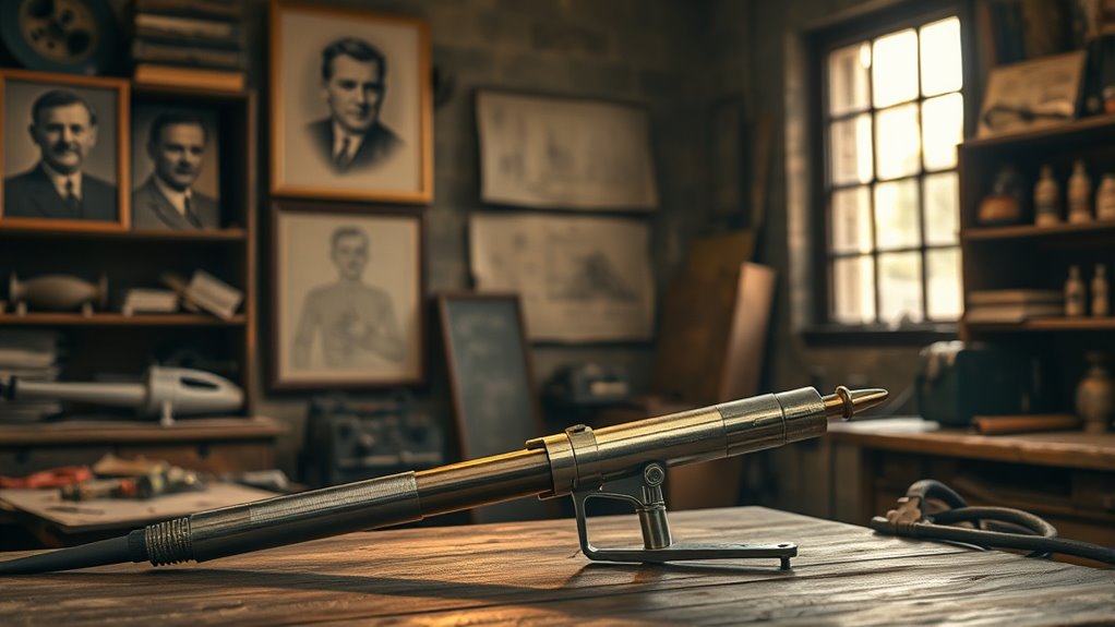
A modern PAW torch normally places a nonconsumable tungsten electrode behind a small, cooled orifice. Plasma gas passes around the electrode and through the opening. A separate shielding-gas stream protects the molten weld pool from the atmosphere.
Many systems use a low-current pilot arc between the electrode and nozzle to start and stabilize the process. The main transferred arc then runs between the electrode and conductive workpiece. Torch cooling, nozzle condition, electrode shape, gas purity, and flow control are critical to stable operation.
Note: Plasma arc welding and plasma arc cutting use the same basic constricted-arc principle, but they are set up for different results. Welding controls the molten pool to join parts; cutting drives a higher-energy jet through the material to separate it.
Products Worth Considering

Gel eliminates erratic operation with a film that will not clog orifices and threads on MIG nozzles and contact tips

Crafted from high-quality durable materials, copper components offer excellent electrical conductivity and heat resistance, stable for high-frequency, high-intensity cutting. .045"/1.1 aperture ideal for 50-60A current.

Fit for: SG-55 AG-60 plasma cutter torch head.
Industrial Adoption and Impact
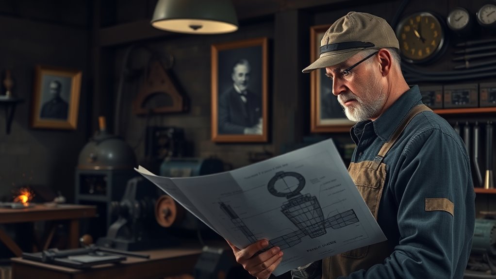
Manufacturers adopted PAW where concentrated heat, repeatability, and automation justified the extra equipment. Fronius lists modern plasma-welding applications in automotive supply, pipeline and container construction, mechanical engineering, structural steelwork, rail vehicles, and shipbuilding.
Precision PAW and GTAW controls are also used for tube, pipe, pressure-vessel, aerospace, and aviation work where torch-to-work distance must remain stable. The exact process must still be qualified for the material, joint, code, and service conditions.
| Application Area | Why PAW May Be Chosen | Important Limitation |
|---|---|---|
| Thin sheet and small components | Stable low-current arc and precise heat placement | Setup and torch condition must be tightly controlled |
| Tube, pipe, and vessels | Repeatable mechanized seams and keyhole capability | Fit-up and procedure qualification are critical |
| Automotive, rail, and shipbuilding | Automation, speed, and concentrated energy | Specialized equipment can cost more than TIG |
How Plasma Arc Welding Works
PAW starts by feeding gas through a torch around a tungsten electrode. Electrical energy ionizes part of that gas, creating a conductive plasma. The cooled nozzle constricts the arc and sends the plasma toward the workpiece.
- Pilot arc starts: A small arc forms between the electrode and nozzle in many PAW systems.
- Main arc transfers: The welding arc establishes between the electrode and conductive workpiece.
- Nozzle constricts the arc: The small opening focuses the arc and plasma-gas flow.
- Base metal melts: The focused energy creates a weld pool or, in keyhole mode, penetrates through the joint.
- Shielding gas protects the weld: The outer gas envelope limits contact with air as the pool solidifies.
Filler metal may be added, but some PAW joints are autogenous, meaning the base-metal edges fuse without filler. The correct setup depends on alloy, thickness, joint design, position, code requirements, and equipment instructions.
Main Plasma Arc Welding Modes
PAW is not one fixed process. Operators select a mode based on current level, gas flow, material thickness, and the required penetration.
- Microplasma: A very stable low-current mode for foil, wire, bellows, screens, and other small or thin parts.
- Melt-in or soft plasma: The arc melts the joint without intentionally opening a full keyhole. It behaves more like a highly focused TIG process.
- Keyhole plasma: Higher arc force opens a small hole through the joint. Molten metal flows around the keyhole and closes behind the torch, allowing deep single-pass penetration in suitable material.
Pro Tip: Treat current, plasma-gas flow, shielding-gas flow, nozzle size, torch height, and travel speed as one system. Changing one variable can alter penetration, keyhole stability, bead shape, and nozzle life.
Products Worth Considering

APPLICATION: Apply to YESWELDER CUT-65DS/CUT-55DS PRO/CUT-55NHF/CUT-55NHF PLUS plasma cutters. Replacement for the S45 Plasma Cutting Torch.

AG60 Plasma Cutter Torch Body / Head compatible with standard of AG60 torch for 60A Plasma Cutting Machine. (i.e. CUT50, CUT60, CUT70.)

Wide Vision and Size: experience convenience with our welding glasses, measured at about 6.3 x 2.95 inches/ 16 x 7.5 cm (L x W), with a 180° viewing angle, you can enjoy the convenience of peripheral vision; The Shade 5 IR lens delivers a clear view, enhancing your performance and efficiency during various types and phases of welding
Advantages and Limitations of Plasma Arc Welding
| Potential Advantages | Practical Limitations |
|---|---|
| Stable, concentrated arc | More complex torch and controls than basic TIG |
| Fine low-current control and deep keyhole options | Sensitive to nozzle wear, contamination, and gas settings |
| Good repeatability in mechanized welding | Joint fit-up and torch alignment can be demanding |
| Potential for narrow welds and high travel speed | Equipment, training, and maintenance costs may be higher |
PAW may reduce distortion in a well-designed procedure because the concentrated arc can shorten heating time or narrow the weld. However, it is not correct to promise a smaller heat-affected zone in every comparison with TIG. Heat input, travel speed, current, mode, joint geometry, and material properties determine the final result.
Recognition and Legacy in Welding

Gage’s 1957 patent established the essential constricted-arc torch concept in a formal technical record. The same basic idea continues in equipment used for plasma welding, plasma cutting, transferred-arc surfacing, heating, and related thermal processes.
Gage’s Impact on Industry
The invention expanded the useful range of tungsten-electrode arc processes. It gave manufacturers a controllable arc for delicate components, mechanized seams, and deeper-penetration joints. It also helped make plasma cutting a practical industrial process for electrically conductive metals.
Historical Significance of the Innovation
Gage’s work matters because it changed the geometry of the arc. The nozzle did more than direct gas; it constrained the arc itself. That principle improved control and opened the door to specialized process modes that an open TIG arc could not duplicate in the same way.
The Evolution of Plasma Arc Techniques
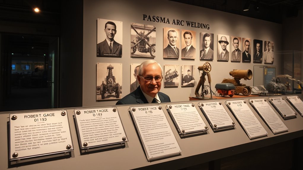
Later systems added better cooling, digital current control, precise gas metering, mechanized travel, arc-voltage control, and robotic torch packages. These improvements increased repeatability and made it easier to record and reproduce qualified settings.
Modern equipment can support manual or robotic operation and may cover microplasma, soft-plasma, and keyhole work. Available current ranges, gases, polarity, duty cycle, and material capability vary by machine, so operators should follow the equipment manual and an approved welding procedure.
Plasma Arc Welding vs. TIG Welding
PAW and TIG both commonly use a nonconsumable tungsten electrode and an inert shielding environment. The main difference is the PAW torch’s constricting nozzle and separate plasma-gas path.
| Feature | Plasma Arc Welding | TIG Welding |
|---|---|---|
| Arc shape | Constricted through a nozzle | Open arc from electrode to workpiece |
| Process range | Microplasma, melt-in, and keyhole modes | Broad manual and automated welding range |
| Equipment | Special torch, plasma-gas control, cooling, and pilot-arc system | Usually simpler and more widely available |
| Best fit | Specialized precision or mechanized work | General-purpose high-quality welding and repair |
TIG is often the practical choice when portability, lower equipment cost, and broad shop familiarity matter. PAW can be the better choice when a procedure needs a highly stable low-current arc, keyhole penetration, or tightly repeatable mechanized welding.
Plasma Arc Welding Safety
Warning: PAW exposes operators and nearby workers to intense ultraviolet and infrared radiation, hot metal, fumes and gases, fire hazards, compressed gas, and electric shock. Use trained personnel, local exhaust or other suitable ventilation, flame-resistant clothing, gloves, safety footwear, screens, and properly selected eye and face protection. Never weld on an uncleaned container or in a confined space without the required controls and permit procedures.
OSHA identifies welding hazards that include metal fumes, ultraviolet radiation, burns, eye injury, and electrical shock. OSHA also publishes minimum protective shade numbers for PAW based on current: shade 6 below 20 A, shade 8 from 20–100 A, shade 10 from 100–400 A, and shade 11 from 400–800 A. Start with a lens that is too dark, then move lighter without going below the applicable minimum or the equipment and workplace requirements.
Keep chlorinated degreasing vapors away from arc-welding areas, remove or shield combustibles, inspect cables and gas connections, keep the work lead secure, and use hearing protection when noise levels require it. Follow the machine manual, safety data sheets, the qualified welding procedure, and applicable workplace rules.
Frequently Asked Questions
Who invented plasma arc welding?
Robert M. Gage is credited with inventing the constricted plasma-arc torch used for plasma arc welding. He developed the work within Union Carbide’s Linde organization, and the resulting U.S. patent was issued in 1957.
Was plasma arc welding invented in 1953 or 1955?
Secondary histories often cite 1953, but the strongest primary record shows that Gage filed the patent application on July 26, 1955. ESAB’s history also places Linde’s plasma-arc cutting milestone in 1955. The patent was issued on September 10, 1957.
Is plasma arc welding the same as plasma cutting?
No. Both use a constricted plasma arc, but PAW controls a weld pool to join metal. Plasma arc cutting uses a more forceful jet to melt and remove material through the thickness of an electrically conductive workpiece.
What safety measures are required for plasma arc welding?
Use a welding helmet with the correct filter shade, safety glasses, flame-resistant clothing, gloves, suitable footwear, welding screens, ventilation, and fire controls. Inspect the torch, cooling system, cables, work lead, and gas connections before use. Confined-space and hot-work rules may require permits, monitoring, attendants, and rescue planning.
How does plasma arc welding differ from TIG welding?
Both often use a tungsten electrode and inert shielding gas. PAW places the electrode inside a torch and constricts the arc through a nozzle. TIG uses a more open arc. PAW adds process modes and arc concentration, while TIG usually uses simpler, more common equipment.
What materials can be welded with plasma arc welding?
PAW can weld many metals also suited to TIG, including stainless steel, nickel alloys, titanium, aluminum, and other ferrous or nonferrous alloys. Actual suitability depends on the machine, polarity, shielding and plasma gases, joint design, material condition, and qualified procedure.
What are the energy requirements for plasma arc welding?
There is no single power requirement. Microplasma systems use low current, while keyhole welding uses more current and arc force. Input power, duty cycle, cooling, gas flow, and outlet requirements vary by machine, so the equipment nameplate and manual control the installation.
How does PAW affect weld quality and precision?
The constricted arc can improve arc stability, heat placement, penetration control, and repeatability. Weld quality still depends on clean material, sound fit-up, correct gases, stable torch height, maintained consumables, suitable settings, and qualified technique.
Conclusion
Robert M. Gage invented the constricted plasma-arc torch that became the foundation of plasma arc welding. The primary patent record shows a 1955 application and a 1957 issue date, with Union Carbide Corporation as assignee and Linde identified in company history as the operating division. Gage’s lasting achievement was precise arc control: the cooled nozzle shaped and directed the arc, enabling microplasma, melt-in, keyhole, automated welding, and related plasma-cutting technology.
Sources
- U.S. Patent 2,806,124, Arc Torch and Process — inventor, assignee, filing date, issue date, and constricted-arc design.
- ESAB: The Story of Welding — Linde’s relationship to Union Carbide and the 1955 plasma-arc milestone.
- Fronius Plasma Welding — modern system components, materials, and industrial applications.
- Lincoln Electric Arc Voltage Control — torch-height control in precision GTAW and PAW applications.
- OSHA Welding, Cutting, and Brazing Hazards — fumes, radiation, burns, eye injury, and electrical hazards.
- OSHA 1915.153 Eye and Face Protection — minimum PAW filter-shade numbers by arc current.