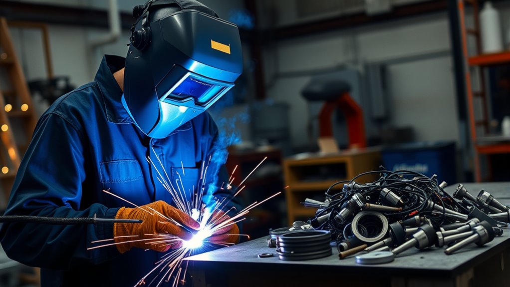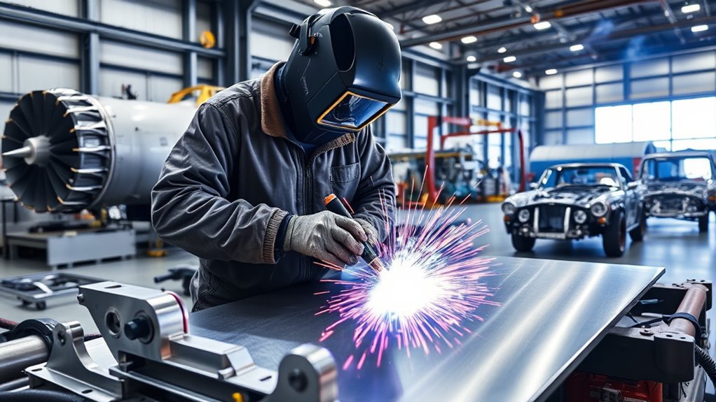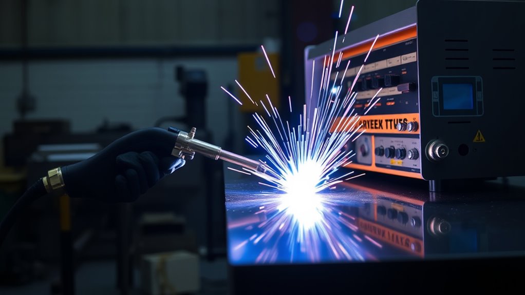
Keyhole plasma arc welding, often shortened to KPAW, uses a tightly constricted plasma arc to produce deep penetration through a joint. It can complete some welds in one pass with less joint preparation than conventional TIG welding, but the process is not controlled by one universal set of numbers. Reliable results depend on matching the current, gas flow, travel speed, nozzle, joint fit-up, material, and start-stop sequence.
Quick Answer
Keyhole plasma arc welding uses a constricted plasma arc to open a temporary hole through the joint while molten metal closes behind it. It can produce deep, full-penetration welds at higher speeds than conventional TIG, but only inside a qualified parameter window. Thickness, gas, current, travel speed, joint fit-up, and start-stop control must be matched to the material.
Key Takeaways
- KPAW forms a controlled keyhole that allows full penetration while molten metal closes behind the arc.
- Keyhole operation commonly uses more than 100 A, but current alone does not determine a safe or successful setup.
- Up to 10 mm single-pass capability is commonly cited for stainless steel, while approximately 6 mm is a more usual practical limit without additional preparation.
- Autogenous square-butt welding is possible, but filler metal and groove preparation are still used when the joint, thickness, bead profile, or governing procedure requires them.
- Most production KPAW is mechanized or automated because the stable operating window can be narrow.
- Use a qualified welding procedure, verified trial coupons, and the torch manufacturer’s setup data instead of copying generic parameter values.
Last updated: July 20, 2026.
Overview of Keyhole Plasma Arc Welding
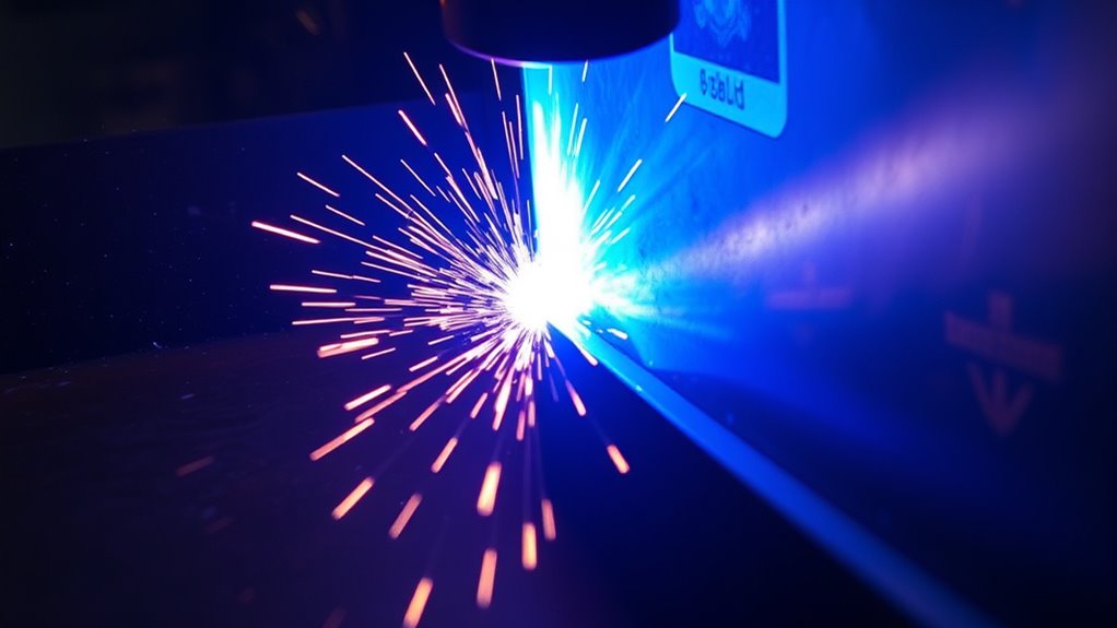
Plasma arc welding is related to TIG welding because both processes use a nonconsumable tungsten electrode. The main difference is that a water-cooled copper nozzle constricts the plasma arc before it reaches the workpiece. This creates a narrower, stiffer arc with a higher energy density than a conventional TIG arc.
A typical transferred-arc system first creates a small pilot arc between the tungsten electrode and the nozzle. When the welding cycle begins, the main arc transfers to the workpiece. A separate plasma gas passes through the nozzle bore, while an outer shielding gas protects the weld pool from the atmosphere.
In keyhole mode, higher current and plasma-gas momentum push through the molten joint and create a temporary opening. As the torch travels, molten metal flows around the opening and closes behind it under surface-tension forces. When the current, gas flow, travel speed, fit-up, and torch position stay balanced, the closed pool forms a fully penetrated weld.
TWI divides plasma welding into microplasma, medium-current or melt-in welding, and keyhole welding. Keyhole operation is generally associated with currents above 100 A, but that threshold describes the process mode rather than a recommended setting for every weld.
Microplasma, Melt-In, and Keyhole Modes
- Microplasma welding: Uses very low current for thin sheet, foil, wire, mesh, and small precision parts.
- Melt-in plasma welding: Melts the joint without intentionally opening a through-keyhole. It behaves more like a concentrated TIG process.
- Keyhole plasma welding: Uses enough arc force and energy density to create and maintain a through-hole that closes behind the torch.
Note: Full penetration is not automatic just because a machine is set above 100 A. A sound keyhole exists only within a stable operating window for the specific material, thickness, joint, torch, nozzle, gas, and welding position.
Benefits of Keyhole Plasma Arc Welding
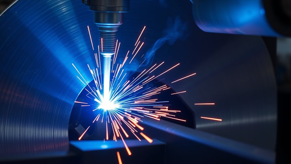
The main benefit of KPAW is deep penetration from a concentrated arc. In a suitable square-butt joint, this can reduce the number of weld passes and the amount of edge preparation compared with conventional TIG welding.
TWI reports single-pass keyhole capability up to about 10 mm in stainless steel, but notes that approximately 6 mm is a more usual limit for single-pass production welding.
Deep Penetration and Fewer Passes
A square-butt KPAW procedure may replace a multi-pass TIG joint in the thickness range supported by the material, equipment, and welding procedure. Fewer passes can reduce arc time, interpass cleaning, filler consumption, and the number of opportunities for defects between layers.
Concentrated Heat Input
The constricted arc can produce a narrow weld and heat-affected zone compared with a broader conventional TIG arc. This may reduce distortion, but it does not eliminate it. Restraint, heat input, material properties, joint geometry, travel sequence, and fixture design still affect the final shape.
Less Preparation and Filler in Suitable Joints
Autogenous welding without continuously added filler is possible on accurately fitted joints. However, filler metal is often used to improve the top-bead profile, prevent underfill, close the keyhole at the end of the weld, or meet chemistry and mechanical-property requirements.
For thicker sections, a prepared groove may be used above a keyhole root face. The correct design must come from a qualified procedure rather than a general thickness rule.
Automation and Repeatability
KPAW works well with mechanized seam welders, orbital equipment, robotic cells, and programmable gas and current controls. Automation can hold the torch position and travel speed more consistently than manual movement.
Fronius reports that plasma keyhole welding can be as much as 100% faster than conventional TIG in certain applications. That figure is manufacturer- and application-specific, so it should not be treated as a guaranteed production increase.
Equipment Used for Keyhole Plasma Arc Welding
A complete KPAW installation normally includes more than a welding power source and torch. The major components are:
- DC welding power source: Supplies the main transferred arc and may provide pulsed-current functions.
- Plasma control console: Controls the pilot arc, main current sequence, plasma gas, shielding gas, and cooling system.
- Plasma torch: Holds the tungsten electrode inside a water-cooled copper constricting nozzle.
- Cooling unit: Removes heat from the torch and nozzle during high-current operation.
- Plasma and shielding-gas supply: Uses separate regulated gas circuits with flow control.
- Travel system: Moves the torch or workpiece at a controlled speed along the joint.
- Wire feeder: Adds filler continuously or only during startup and termination when required.
- Fixture and joint-tracking system: Controls alignment, gap, torch height, and seam position.
- Root shielding or trailing shielding: Protects reactive materials and the back of full-penetration welds when the procedure requires it.
- Process monitoring: Records current, voltage, gas flow, travel speed, coolant flow, and alarms for quality control.
Purpose-built plasma systems are common, although some conventional TIG systems can be expanded with a plasma console, compatible torch, gas controls, and the required software or hardware package.
Products Worth Considering

9-IN-1 WELDER:ARCCAPTAIN MIG205MP MIG welder has 9 welding modes: Gas MIG/Gasless MIG/Cut/DC HF TIG/DC Lift TIG/MMA Stick/Clean/Spot Welding/Spool Gun Aluminum Welding (Need to buy extra spool gun). This multiprocess welder perfectly handles all your needs—from home DIY and garage projects to outdoor repairs, farm equipment, and road maintenance and repairs.

2 IN 1 Multi-functional Design:FEMEROL integrates 60A plasma cutter and 200A MMA stick welder in one unit, supporting plasma cutting and MMA welding dual modes to meet various working needs. It works perfectly for stainless steel, alloy steel, mild steel, copper, aluminum and most common metal materials.

Used Book in Good Condition
Key Settings for Optimal KPAW Performance
Warning: Do not use generic current, gas-flow, or travel-speed figures as a production welding procedure. Incorrect settings can cause loss of penetration, excessive root reinforcement, undercut, porosity, double arcing, nozzle failure, or an unstable molten pool. Use the equipment manual, a qualified welding procedure specification, and verified test coupons.
KPAW settings work as a system. Changing one variable can shift the entire keyhole operating window.
| Variable | What It Controls | Risk When Incorrect |
|---|---|---|
| Welding current | Heat input, penetration, arc pressure, and keyhole formation | Incomplete penetration at low current; excessive root bead, undercut, or burn-through at excessive current |
| Plasma gas flow | Arc constriction, momentum, penetration, and keyhole stability | Keyhole collapse if too low; turbulence, undercut, gas entrainment, or nozzle damage if too high |
| Travel speed | Heat input per unit length and time available for the pool to close | Excessive penetration or a wide pool if too slow; incomplete fusion or an unstable keyhole if too fast |
| Nozzle bore | Arc constriction, current capacity, gas velocity, and torch life | Erosion or melting if too small; weak constriction or poor keyhole stability if too large |
| Torch height and alignment | Arc position, penetration symmetry, and protection of the nozzle | Uneven penetration, undercut, arc instability, or nozzle contact |
| Shielding gas | Arc behavior, oxidation control, heat transfer, and weld chemistry | Porosity, oxidation, embrittlement, poor bead shape, or an incompatible metallurgical reaction |
| Joint gap and mismatch | Pool support, root shape, and keyhole closure | Underfill, sagging, inconsistent penetration, or loss of the keyhole |
| Filler-wire rate | Reinforcement, chemistry, undercut control, and keyhole closure | Underfill if insufficient; cold lap, excessive reinforcement, or pool instability if excessive |
Products Worth Considering

APPLICATION: Apply to YESWELDER CUT-65DS/CUT-55DS PRO/CUT-55NHF/CUT-55NHF PLUS plasma cutters. Replacement for the S45 Plasma Cutting Torch.

AG60 Plasma Cutter Torch Body / Head compatible with standard of AG60 torch for 60A Plasma Cutting Machine. (i.e. CUT50, CUT60, CUT70.)

Wide Vision and Size: experience convenience with our welding glasses, measured at about 6.3 x 2.95 inches/ 16 x 7.5 cm (L x W), with a 180° viewing angle, you can enjoy the convenience of peripheral vision; The Shade 5 IR lens delivers a clear view, enhancing your performance and efficiency during various types and phases of welding
Current and Travel Speed
Keyhole welding commonly operates above 100 A, but the required current may be much higher for a particular material or section. Current must be developed together with travel speed and plasma flow. Increasing current without adjusting the other variables can enlarge the keyhole or overheat the root.
Plasma and Shielding Gases
TWI lists argon as a common plasma gas and argon with 2–5% hydrogen as a common shielding-gas combination for compatible applications. This is not a universal recommendation. Hydrogen-containing gas may be unsuitable for some materials or procedures, while reactive metals can require high-purity inert shielding and extended trailing or root protection.
Use only the gas specified by the equipment manufacturer and qualified procedure. Check gas purity, hose condition, regulator capacity, flow calibration, and leaks before production begins.
Electrode and Nozzle Geometry
A tungsten tip angle of approximately 30–60° is commonly used in plasma welding, subject to the torch manufacturer’s instructions. The nozzle bore must match the current and gas-flow range. A bore that is too small can overheat or erode, while an oversized bore may weaken arc constriction and make the keyhole difficult to maintain.
Startup and Termination
A production program normally ramps current, plasma flow, wire feed, and travel speed through separate startup, steady-state, and termination stages. The starting sequence allows the pool and keyhole to form without leaving a large root defect.
At the end of the seam, the system must close and fill the keyhole before extinguishing the arc. Depending on the procedure, this may involve reducing plasma flow and current, slowing or changing travel, adding filler wire, using a run-off tab, or overlapping a circumferential weld.
NASA’s documented keyhole PAW method coordinates current, plasma flow, travel speed, and filler during startup and shutdown to prevent an unfilled terminal keyhole and related defects.
Pro Tip: Develop the steady-state weld first on test coupons, then qualify the startup and termination programs separately. Many visually acceptable seams fail at the first or last few millimeters because the keyhole was not formed or closed under controlled conditions.
Suitable Materials and Joint Designs
KPAW can be used on several weldable metals, but each material needs its own procedure, gas selection, polarity, cleaning method, and shielding arrangement.
Common Material Groups
- Stainless steels: One of the most established KPAW applications, especially for longitudinal seams, tube, vessels, and accurately fitted butt joints.
- Carbon and low-alloy steels: Suitable when the procedure accounts for hardenability, preheat, hydrogen control, filler selection, and required mechanical properties.
- Nickel alloys: Used for corrosion-resistant and high-temperature components with compatible filler and shielding.
- Titanium alloys: Suitable for high-integrity work but require strict contamination control and extensive inert protection while the metal remains hot.
- Aluminum alloys: Commonly associated with specialized variable-polarity plasma arc welding, which provides oxide-cleaning action and differs from ordinary DC keyhole welding.
NASA documented variable-polarity plasma arc welding for aluminum Space Shuttle external-tank fabrication, including production welding on liquid-oxygen and liquid-hydrogen cylinders. That application used a specialized aerospace procedure and should not be treated as proof that aluminum is automatically easy to weld with standard KPAW equipment.
Thickness and Joint Preparation
There is no single thickness limit for all KPAW systems. TWI describes single-pass capability up to about 10 mm in stainless steel but states that approximately 6 mm is a more usual production limit. Fronius lists no-preparation ranges of 3–8 mm for steel and 3–10 mm for chromium-nickel material for its plasma systems.
Those ranges describe process capability under suitable conditions, not a guaranteed result for every alloy, position, joint, or machine.
- Square-butt joint: Common for autogenous or low-filler keyhole welding within the qualified thickness range.
- Prepared V-groove: Used on thicker sections, often with a root face that can still be penetrated in keyhole mode.
- Longitudinal tube seam: Well suited to fixed tooling and repeatable mechanized travel.
- Circumferential or orbital seam: Possible with pulsed or position-compensated control, but gravity changes pool behavior around the joint.
Fit-Up and Surface Preparation
Clean the joint to the level required by the alloy and procedure. Remove oil, moisture, paint, scale, oxide, and other contaminants that could produce porosity or arc instability. Reactive alloys may require dedicated tools and controlled handling to prevent contamination.
Maintain the specified root gap, mismatch, edge condition, and torch-to-joint alignment. KPAW generally has less tolerance for large or changing gaps than a filler-rich MIG/MAG process because the keyhole pool must remain supported and close consistently.
Applications of Keyhole Plasma Arc Welding
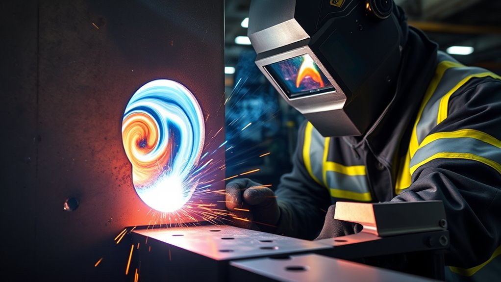
KPAW is most valuable when the joint is repeatable, full penetration is required, and mechanized travel can hold a narrow process window.
Aerospace and High-Integrity Tanks
Variable-polarity PAW has documented historical use on aluminum aerospace tanks and related structures. Other plasma-welding variants may be selected for stainless, nickel, or titanium aerospace components when the process has been qualified for the specific alloy and design.
Tube Mills and Longitudinal Seams
Tube, pipe, bellows, and cylindrical components are strong candidates because the seam can be positioned accurately under a fixed torch. Manufacturers may use KPAW to reduce the number of passes and increase line speed compared with conventional TIG.
Pressure Vessels and Process Equipment
Stainless and corrosion-resistant vessels, tanks, heat-exchanger components, and chemical-processing equipment may use plasma welding where full penetration, repeatability, and a narrow seam are important.
Pipe and Orbital Welding
Keyhole plasma orbital welding can join carbon steel, stainless steel, nickel alloys, and titanium pipe. Position changes around the circumference affect gravity, keyhole shape, and pool closure, so pulsed current and position-specific programs may be necessary.
Nuclear and Energy Fabrication
KPAW may be used in qualified nuclear, power-generation, and energy applications when the process, operator, equipment, filler, inspection plan, and acceptance criteria meet the governing code and project requirements.
Marine and hull-related fabrication may also use plasma welding for selected components, but process choice depends on plate thickness, steel grade, access, position, code, repairability, and production economics. KPAW should not be described as a universal submarine-hull process.
Common KPAW Defects and Troubleshooting
Most KPAW defects come from losing the balance between arc energy, plasma momentum, travel speed, molten-pool support, and shielding.
| Problem | Likely Causes | Corrective Direction |
|---|---|---|
| Incomplete penetration or keyhole collapse | Insufficient current or plasma flow, excessive speed, excessive thickness, wrong torch height, poor alignment, or a worn nozzle | Return to the qualified procedure, verify calibration and consumables, and adjust only through controlled coupon testing |
| Excessive root reinforcement or burn-through | Excessive current or plasma flow, low travel speed, oversized gap, poor backing, or inadequate pool support | Check fit-up and backing, then rebalance current, speed, and plasma flow within the approved range |
| Undercut or underfill | Excessive arc force or speed, inadequate filler, incorrect wire position, or unstable top-surface flow | Verify filler addition, wire placement, travel speed, torch position, and gas-flow balance |
| Porosity or oxidation | Contaminated joint, moisture, gas leaks, turbulence, poor shielding coverage, or insufficient root protection | Clean and dry the joint, leak-test the system, verify gas purity and flow, and improve shielding coverage |
| Double arcing or nozzle erosion | Nozzle bore too small, excessive current or plasma flow, damaged insulation, contamination, poor cooling, or nozzle contact | Stop welding, inspect the torch, confirm coolant flow, and install the correct clean consumables |
| Terminal crater, pore, or open keyhole | Arc stopped before the pool closed, inadequate filler, abrupt gas or current reduction, or no run-off provision | Qualify a controlled downslope and filler sequence, overlap the seam, or use a run-off tab |
| Variable penetration along the seam | Changing gap, mismatch, torch height, travel speed, gas flow, heat sinking, or nozzle condition | Improve fixturing and joint tracking, calibrate the system, and monitor consumable wear and parameter data |
Do not correct a production defect by changing several variables at once. Record the original values, inspect the equipment and joint first, change one controlled factor, and confirm the result with macro examination or the required nondestructive testing.
Limitations and Challenges of KPAW
KPAW offers high penetration and productivity, but it is less forgiving than many general-purpose welding processes.
Higher Equipment and Integration Cost
The system may require a dedicated torch, plasma console, cooling unit, separate gas circuits, automated motion, joint tracking, fixtures, wire control, and process monitoring. This can be difficult to justify for short runs or frequently changing parts.
Narrow Process Window
A small change in root gap, nozzle wear, torch height, gas flow, or speed can move the process from full penetration to undercut, excessive penetration, or keyhole collapse.
Mechanization Is Usually Needed
TWI notes that keyhole parameters and filler addition must be carefully balanced, which makes the technique primarily suitable for mechanized welding. Manual plasma welding exists, but sustained production keyhole welding normally benefits from programmed travel and gas control.
Joint Fit-Up Requirements
KPAW may eliminate edge preparation in a suitable thickness range, but it does not eliminate precision. Inconsistent gaps and edge mismatch can destabilize the molten pool or change the root bead.
Position and Gravity Effects
Flat-position seams are easier to control. Vertical, overhead, horizontal, and orbital joints may require pulsed current, lower pool volume, filler changes, or separate programs for different positions.
Torch and Consumable Maintenance
The copper nozzle, tungsten position, internal insulation, cooling passages, collets, seals, and gas paths must remain clean and correctly assembled. Nozzle erosion changes the arc and can shift a previously stable procedure out of tolerance.
Procedure Qualification and Inspection
A visually smooth bead does not prove complete fusion or an acceptable root. Production procedures may require macro sections, tensile or bend testing, radiography, ultrasonic testing, penetrant testing, leak testing, or other examination according to the governing code.
Comparing KPAW to Other Welding Techniques
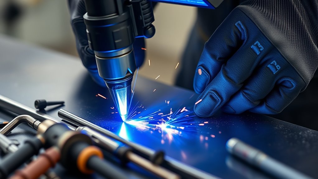
| Process | Main Strength | Main Limitation | Best Fit |
|---|---|---|---|
| KPAW | Deep, narrow penetration with possible single-pass square-butt welding | Narrow process window, precise fit-up, specialized torch, and mechanization | Repeatable longitudinal, orbital, vessel, tube, and high-integrity seams |
| TIG/GTAW | Excellent control, clean welds, and broad manual usefulness | Lower penetration and slower multi-pass welding on thicker joints | Thin material, repair, root passes, complex shapes, and lower-volume work |
| MIG/MAG/GMAW | High deposition rate, good productivity, and greater gap-filling ability | Requires filler wire and may produce more spatter or a wider weld profile | General fabrication, fillets, structural work, and joints needing added metal |
| Laser welding | Very high speed, narrow welds, and deep penetration | Higher capital cost, beam-safety controls, and demanding fit-up | High-volume precision production with strong automation support |
| Friction stir welding | Solid-state joining with low fusion-related porosity and distortion | Requires strong clamping, backing support, tool access, and specialized machinery | Long aluminum seams and other applications suited to solid-state joining |
Compared with TIG, KPAW generally offers deeper penetration, higher travel speed, and a narrower heat-affected zone. TIG remains easier to apply manually and can tolerate a wider variety of low-volume repair situations.
Compared with MIG/MAG, KPAW can make autogenous full-penetration seams without continuously depositing filler. MIG/MAG is usually more flexible for fillet welds, variable gaps, structural fabrication, and applications requiring a high deposition rate.
Laser welding can exceed KPAW in speed and energy concentration but usually requires a larger capital investment and strict laser-safety infrastructure. KPAW can occupy the middle ground between conventional arc welding and beam welding for repeatable medium-thickness seams.
Friction stir welding is fundamentally different because it joins material below the melting point. It is especially important for aluminum structures, but it requires substantial clamping, backing, and tool access. KPAW remains useful where a fusion process, nonrotating torch, or particular joint geometry is preferred.
KPAW Safety and Operator Qualification
Warning: KPAW exposes workers to intense ultraviolet and infrared radiation, hot metal, welding fumes, electrical current, pressurized gases, hot-work fire hazards, and automated machine movement. Use trained personnel, appropriate eye and face protection, flame-resistant clothing, gloves, ventilation or fume extraction, electrical isolation, machine guarding, and a site-approved hot-work procedure.
OSHA’s general welding requirements call for suitable helmets or hand shields during arc welding, protective clothing, fire precautions, and adequate ventilation under applicable workplace conditions.
Essential Safety Controls
- Use a welding helmet and filter shade appropriate for the actual current and operation.
- Protect nearby workers with noncombustible welding screens.
- Use local exhaust ventilation where needed to keep fumes out of the breathing zone.
- Assess material-specific hazards, especially when welding stainless steel, nickel alloys, coated metal, or contaminated surfaces.
- Remove flammable materials and provide a fire watch when the hot-work assessment requires one.
- Check torch cooling, cable insulation, work-return connections, interlocks, and emergency stops.
- Secure cylinders and verify that regulators, hoses, flashback protections, and gas systems are suitable for the gases used.
- Follow special controls for hydrogen-containing mixtures and never improvise a gas blend.
- Guard mechanized travel, positioners, clamps, and robotic cells against crushing and unexpected movement.
- Use confined-space permits, atmospheric testing, ventilation, attendant procedures, and rescue planning when applicable.
Training and Qualification
Operators need process-specific training in torch assembly, gas control, parameter programming, joint fit-up, consumable inspection, defect recognition, emergency shutdown, and safe handling of the selected gases and materials.
There is no universal credential called a KPAW certification. Qualification depends on the governing contract, code, employer, quality system, and jurisdiction. ISO 14732:2025 specifies qualification requirements for welding operators and weld setters involved in mechanized and automatic welding. Other projects may use AWS, ASME, API, aerospace, nuclear, or customer-specific requirements.
When KPAW Is the Right Choice
KPAW is a strong candidate when most of the following conditions apply:
- The joint is a repeatable butt seam rather than a changing repair or open fillet.
- Full penetration is required and can be verified.
- The material and thickness fall within a proven process range.
- Joint edges can be machined, formed, and fixtured consistently.
- Mechanized or automated travel is available.
- Reduced pass count or joint preparation can justify the equipment and development cost.
- The production volume supports procedure qualification and dedicated tooling.
- The shop can maintain gas quality, cooling, torch consumables, and parameter calibration.
- Inspection methods are available to confirm penetration and internal quality.
TIG or MIG/MAG may be more practical for short repairs, irregular joints, large fit-up variations, field work, fillet welds, or production that cannot support dedicated KPAW tooling. Laser or friction stir welding may be better when their speed, material response, or solid-state advantages justify the higher equipment and fixture requirements.
Frequently Asked Questions
What materials are best suited for keyhole plasma arc welding?
Stainless steel is one of the most established KPAW materials. Carbon steels, low-alloy steels, nickel alloys, and titanium can also be suitable with the correct procedure and shielding. Aluminum is normally treated as a specialized variable-polarity plasma application rather than an automatically easy material.
How thick can KPAW weld in one pass?
The limit depends on the material, torch, power source, joint, position, and qualified procedure. TWI cites up to about 10 mm for stainless steel but says approximately 6 mm is a more usual single-pass limit. Thicker sections may need a prepared groove, filler metal, or multiple passes.
Does keyhole plasma welding require filler metal?
Not always. Accurately fitted square-butt joints can be welded autogenously, but filler may be added to control reinforcement, prevent underfill, adjust weld chemistry, meet mechanical-property requirements, or fill the keyhole during termination.
Can KPAW be automated for large-scale production?
Yes. Mechanized seam welders, orbital systems, robots, programmable power sources, joint tracking, and closed-loop gas controls can provide repeatable travel and parameter control. Automation is especially useful because keyhole stability can be sensitive to small process changes.
How does KPAW affect energy use and the environment?
A suitable single-pass procedure may reduce arc time, filler use, edge preparation, and rework compared with a multi-pass process. That does not automatically make every KPAW operation more sustainable. Total impact also depends on electricity, shielding gas, cooling, extraction, consumables, scrap, and production efficiency.
What safety precautions are necessary for KPAW operators?
Operators need suitable arc-rated eye and face protection, flame-resistant clothing, gloves, ventilation or fume extraction, electrical protection, hot-work controls, safe gas handling, machine guarding, and training on the specific equipment. Confined spaces and hazardous coatings require additional controls.
Is specialized training or certification required?
Process-specific training is necessary. Formal qualification is required when the governing contract, employer, application standard, code, or quality system calls for it. ISO 14732:2025 covers qualification of operators and setters for mechanized and automatic welding, but there is no single universal credential named KPAW certification.
Conclusion
Keyhole plasma arc welding can produce deep, narrow, full-penetration welds with fewer passes and less joint preparation than conventional TIG in a suitable application. Its strongest uses are repeatable butt seams that can be accurately fixtured and welded with mechanized or automated equipment.
The process is not defined by a universal current, gas-flow rate, speed, or 10 mm thickness rule. A reliable KPAW procedure must balance material, thickness, nozzle bore, current, plasma flow, shielding, travel speed, filler, fit-up, startup, and termination. When those controls, safety systems, operator qualifications, and inspection requirements are in place, KPAW can offer excellent productivity and weld quality. When joint variation or low production volume makes that control impractical, TIG, MIG/MAG, laser, or friction stir welding may be a better choice.
Sources
- TWI: Plasma Arc Welding — process modes, current ranges, materials, gases, nozzle guidance, thickness capability, and mechanized keyhole welding.
- Fronius: Plasma Welding — equipment principles, application-specific preparation ranges, speed comparisons, and plasma-versus-TIG characteristics.
- NASA Technical Reports Server: Method for Defect-Free Keyhole Plasma Arc Welding — coordinated startup, steady-state, filler, gas-flow, and termination control.
- NASA Technical Memorandum: Variable-Polarity PAW for the Space Shuttle External Tank — documented aluminum aerospace application.
- OSHA 29 CFR 1910.252 — welding eye protection, protective clothing, ventilation, fire prevention, and confined-space controls.
- ISO 14732:2025 — qualification testing for welding operators and weld setters in mechanized and automatic welding.