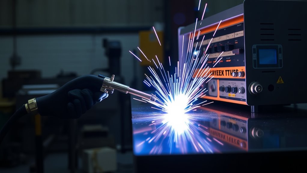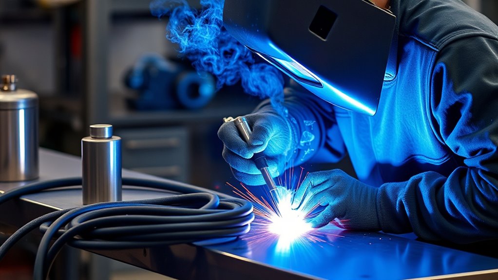
Plasma arc welding (PAW) uses a non-consumable tungsten electrode and a water-cooled constricting nozzle to produce a narrow, stable arc. The focused heat can deliver precise welds, deep penetration, and repeatable results on suitable metals, but only when the torch, gases, current, travel speed, joint fit-up, and safety controls match a qualified procedure.
Quick Answer
Plasma arc welding constricts an arc through a fine nozzle, creating a concentrated plasma stream between a tungsten electrode and the workpiece. The process offers precise heat control and can produce narrow, deep welds. Reliable results depend on correct electrode alignment, gas selection, cooling, fit-up, current, and travel speed.
Key Takeaways
- PAW is related to TIG welding, but a cooled nozzle constricts the arc and raises its energy density.
- The system normally uses separate plasma and shielding-gas circuits, plus a dedicated torch, power source, work lead, and cooling unit.
- Microplasma, melt-in, and keyhole modes cover different current levels, material thicknesses, and penetration needs.
- Gas type and flow are procedure-specific; hydrogen-containing mixtures are suitable only for approved alloys and procedures.
- PAW is sensitive to electrode recess, nozzle condition, joint fit-up, torch angle, travel speed, and gas flow.
- Welding fumes, ultraviolet radiation, electric shock, hot metal, fire, and oxygen displacement require formal controls and trained operators.
At a Glance
| Best For | Precision welding, controlled penetration, thin components, suitable full-penetration seams, and mechanized production |
| Difficulty | Advanced; hands-on training and a written welding procedure are strongly recommended |
| Main Equipment | PAW torch, tungsten electrode, constricting nozzle, compatible power source, gas controls, cooling system, work lead, fixtures, and PPE |
| Common Gases | Argon is common; helium and approved argon-helium or argon-hydrogen mixtures may be used when the alloy, torch, and procedure allow them |
| Main Trade-Off | Greater process control and repeatability, but higher equipment cost and tighter setup tolerances than basic TIG welding |
Understanding the Plasma Arc Welding Process

To understand the plasma arc welding process, start with the torch. PAW places a non-consumable tungsten electrode inside a fine-bore, water-cooled nozzle. The nozzle constricts the arc and the plasma gas flowing around it, creating a narrow, energy-dense column. This is the main difference from the wider, open arc used in TIG welding. Fronius provides a useful manufacturer diagram of the plasma welding principle.
A low-current pilot arc is commonly established between the electrode and nozzle. It ionizes the plasma gas and creates a conductive path. In transferred-arc welding, the main arc then runs between the tungsten electrode and the workpiece. The workpiece becomes part of the welding circuit, allowing concentrated heat to enter the joint.
Transferred and Non-Transferred Arcs
Transferred-arc PAW is the usual arrangement for fusion welding because the main arc transfers to the workpiece. A non-transferred arc remains between the electrode and nozzle and is used more often for heating, spraying, or specialized applications. Do not confuse the non-transferred pilot arc used to start a transferred weld with a process that remains non-transferred during operation.
Shielding gas flows around the outside of the constricting nozzle to protect the molten weld pool and hot metal from the atmosphere. Poor shielding can cause porosity, oxidation, discoloration, contamination, or loss of mechanical and corrosion properties, especially on stainless steel, nickel alloys, aluminum, and titanium.
PAW may be used with or without filler metal. Autogenous welding joins the prepared base-metal edges without added filler. Filler may be needed to control chemistry, reinforce the joint, fill a groove, or complete later passes. The correct choice comes from the welding procedure specification rather than a general rule.
Note: Plasma arc welding is not plasma cutting. PAW controls the arc and molten pool to join metal. Plasma cutting uses a high-velocity plasma jet to melt and eject material from a cut path.
Key Components and Equipment Used in Plasma Arc Welding
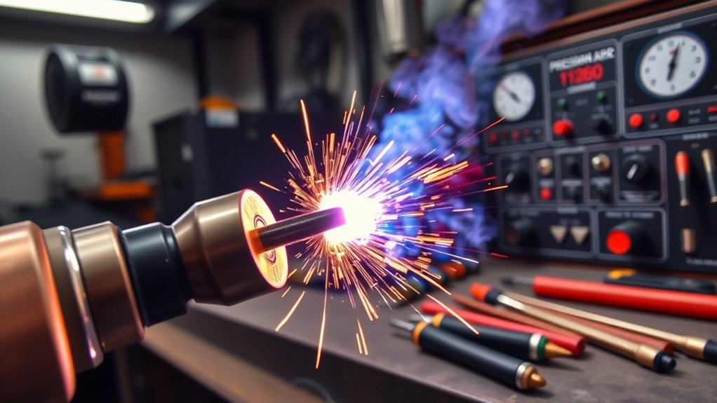
Each part of a PAW system affects arc stability, penetration, weld quality, and safety. The torch must keep the electrode centered in the nozzle while controlling plasma gas, shielding gas, and coolant. The power source must support the process, current range, starting method, and polarity required by the machine and procedure.
Direct current electrode negative (DCEN) is common for many PAW applications. Aluminum and some specialized jobs may require equipment designed for variable-polarity or another approved waveform. Never assume that a TIG power source, torch, or polarity setting is suitable merely because PAW and TIG both use tungsten electrodes.
Many torches are water-cooled because the nozzle is exposed to intense heat. Confirm coolant flow, temperature, and leak-free hoses before striking an arc. Follow the torch manual for coolant type and conductivity; unsuitable coolant can damage components or cause electrical leakage.
| Component | Function | What to Check |
|---|---|---|
| Plasma Torch | Holds the electrode and directs plasma and shielding gases | Correct assembly, insulation, seals, torch angle, and cooling |
| Tungsten Electrode | Carries current and supports the arc | Specified alloy, diameter, tip shape, cleanliness, centering, and recess |
| Constricting Nozzle | Focuses the arc and plasma gas | Correct orifice size; no erosion, double arcing, blockage, or spatter |
| Power Source and Controls | Provides welding current, starting sequence, upslope, downslope, and timing | Compatible mode, polarity, current range, leads, grounding, and program |
| Plasma-Gas Circuit | Ionizes and constricts the arc | Correct gas, regulator, flow control, purity, pressure, and leak-free lines |
| Shielding-Gas Circuit | Protects the weld pool and hot metal | Correct gas and flow; no drafts, leaks, turbulence, or contaminated hoses |
| Cooling System | Removes heat from the torch and nozzle | Coolant level, flow, temperature, conductivity, hoses, and alarms |
| Work Lead and Fixture | Completes the circuit and holds joint alignment | Clean contact, tight connection, correct clamp location, and stable fit-up |
Products Worth Considering

APPLICATION: Apply to YESWELDER CUT-65DS/CUT-55DS PRO/CUT-55NHF/CUT-55NHF PLUS plasma cutters. Replacement for the S45 Plasma Cutting Torch.

AG60 Plasma Cutter Torch Body / Head compatible with standard of AG60 torch for 60A Plasma Cutting Machine. (i.e. CUT50, CUT60, CUT70.)

Wide Vision and Size: experience convenience with our welding glasses, measured at about 6.3 x 2.95 inches/ 16 x 7.5 cm (L x W), with a 180° viewing angle, you can enjoy the convenience of peripheral vision; The Shade 5 IR lens delivers a clear view, enhancing your performance and efficiency during various types and phases of welding
The Role of Plasma and Shielding Gases
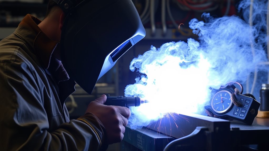
PAW normally uses two gas functions. The plasma gas passes around the electrode and through the nozzle orifice, where it becomes ionized and helps constrict the arc. The shielding gas flows through the outer torch passage and protects the weld pool and hot metal.
Argon is widely used because it supports reliable starting and a stable arc. Helium or argon-helium mixtures can increase heat transfer in approved procedures. Small hydrogen additions are used in some qualified procedures for selected stainless, nickel, or cobalt alloys, but hydrogen is not a universal performance booster. Haynes International notes that small hydrogen additions can raise arc energy in certain autogenous keyhole procedures, while excessive hydrogen can cause porosity. See its PAW process guidance.
Warning: Do not select a hydrogen-containing gas by habit. Aluminum is highly sensitive to hydrogen-related porosity, and titanium requires high-purity inert shielding. Use only the gas listed by the equipment manufacturer and the approved welding procedure for the exact alloy.
Flow rate is also procedure-specific. Too little flow can allow air into the weld zone. Too much flow can create turbulence and draw surrounding air into the gas shield. Nozzle size, current, torch geometry, joint shape, travel speed, backing gas, and shop drafts all affect the correct setting. Use the machine manual, flowmeter range, and welding procedure specification rather than a broad generic liters-per-minute value.
| Gas Choice | Typical Role | Important Limitation |
|---|---|---|
| Argon | Common plasma and shielding gas; stable starting and control | Purity and flow still must match the procedure |
| Helium or Argon-Helium | Can increase heat transfer or alter bead shape | May require different starting, voltage, and flow settings |
| Argon-Hydrogen | Specialized use on approved alloys and procedures | Can cause porosity, cracking, or property loss on unsuitable metals |
| Backing or Purge Gas | Protects the root side of full-penetration or reactive-metal welds | Must prevent air entry without pressurizing a closed volume |
In plasma arc welding, gas flow is a process variable—not merely a shielding accessory. It changes arc constriction, penetration, keyhole stability, contamination risk, and nozzle life.
Optimizing Setup for Effective Plasma Arc Welding
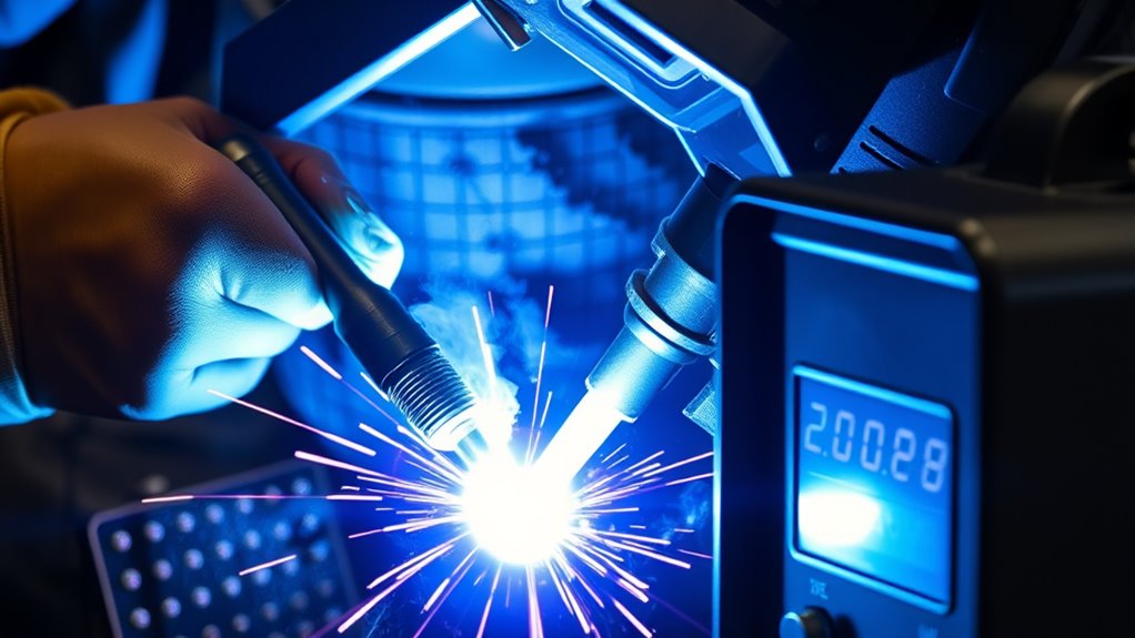
Good PAW results begin before the arc starts. A stable procedure controls electrode position, nozzle size, gas type and flow, current, travel speed, torch height, torch angle, joint gap, and cooling. Changing one variable often changes the effect of several others.
Electrode alignment and recess are especially important. The electrode must be centered within the nozzle, and its setback from the orifice must match the torch manual. An off-center or incorrectly recessed electrode can make the arc wander, cause uneven penetration, overheat the nozzle, or trigger double arcing.
The joint must also be clean and repeatable. Remove oil, paint, moisture, scale, oxide, and unsuitable coatings by an approved method. Use dedicated clean tools for contamination-sensitive metals. Hold the parts with fixtures that maintain the required root opening, mismatch, and alignment throughout the weld.
Products Worth Considering

[Achieve Precise Cuts] PT31 Plasma Cutting Consumables – Your Essential Tool for Efficient Cutting! Whether you're working with sheet metal, steel, or any other material, superior cutting performance ensure clean, accurate, and smooth cuts.
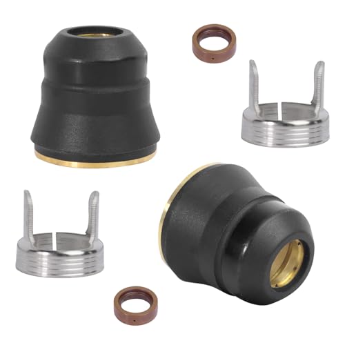
Wide Application: This tip kit replacement is compatible with Harbor Freight Titanium Plasma cutters including models TI-PC45, IPT-45, 56255, 56811/65, Torch TI-PC65, IPT-65, and 58895. It is designed to fit a comprehensive range of systems from the Titanium Plasma 45 to the Titanium 65 Plasma Cutter, ensuring coverage for various cutting tool models

Package includes: 5pcs shield cup, 10pcs ring, 15pcs electrode, 30pcs nozzle
Critical Setup Variables
- Electrode: Install the specified tungsten type, diameter, tip shape, centering, and recess.
- Nozzle: Match the orifice to the current range and mode; replace eroded or damaged parts.
- Plasma Gas: Set the approved gas, purity, pressure, preflow, flow, and postflow.
- Shielding Gas: Confirm the approved gas and coverage without turbulence or drafts.
- Current Program: Set pilot current, main current, upslope, downslope, pulse parameters, and crater-fill sequence as required.
- Travel: Maintain the specified speed, torch-to-work distance, angle, and centerline position.
- Fit-Up: Control gap, edge preparation, mismatch, tack placement, and fixture restraint.
- Cooling: Verify coolant flow and all machine interlocks before welding.
Pro Tip: When a previously stable weld changes, inspect the tungsten, electrode recess, nozzle orifice, gas lines, work connection, and coolant flow before rewriting the current program. Consumable wear can imitate a parameter problem.
Basic Plasma Arc Welding Workflow
This workflow is a general setup sequence, not a substitute for the machine manual, welding procedure specification, employer safety program, or code requirements.
- Review the job documents. Confirm the base-metal grade, thickness, joint design, filler, polarity, gas, current program, travel speed, inspection level, and acceptance criteria.
- Make the area safe. Remove combustibles, install screens, verify ventilation, secure cylinders, inspect electrical leads, and follow any hot-work or confined-space permit requirements.
- Prepare the joint. Clean the metal with an approved method and set the required gap, alignment, backing, purge arrangement, and tack sequence.
- Assemble the torch. Install the correct electrode and nozzle, set electrode recess, tighten components to the manual, and inspect seals and insulation.
- Connect utilities. Attach the work lead to clean metal, connect plasma and shielding gases to the correct circuits, and verify coolant level and flow.
- Load the qualified settings. Enter the approved current, gas, timing, pulse, upslope, downslope, crater-fill, and travel parameters.
- Run a test coupon. Use material and joint geometry representative of the production weld. Check bead shape, penetration, keyhole closure, discoloration, and defects before welding the part.
- Weld with controlled motion. Hold the torch at the specified angle and distance, stay centered on the joint, and maintain steady travel.
- Complete postflow and shutdown. Keep gas coverage during the required postflow, allow the torch to cool, close cylinders as required, relieve pressure safely, and isolate power before maintenance.
- Inspect and document. Perform the required visual and nondestructive examinations, record settings, and quarantine any weld that falls outside acceptance limits.
Warning: Do not “dial in” a structural, pressure, aerospace, medical, or other critical weld directly on the production part. Use qualified procedures, representative test coupons, required operator qualifications, and the inspection rules for the governing code or customer specification.
Common Plasma Arc Welding Modes
PAW can be adjusted for different heat input, arc force, and penetration levels. Terminology varies by manufacturer, but the most common categories are microplasma, melt-in, and keyhole welding.
Microplasma Welding
Microplasma welding uses low current and a small, stable arc. It is useful for thin sheet, wire, bellows, small components, delicate assemblies, and precision repair. The constricted arc can remain stable at low current, but the narrow process window still requires clean parts, accurate fixturing, and controlled travel.
Melt-In Mode
Melt-in mode creates a weld pool without intentionally driving a keyhole through the joint. It is closest in purpose to TIG welding, although the arc is more constricted. It is useful for thin-to-medium sections, root passes, fillets where the torch can access the joint, and applications that value controlled bead shape.
Keyhole Mode
Keyhole mode uses enough arc energy and plasma force to form a small opening through the joint. Molten metal flows around the opening and closes behind the torch, creating a full-penetration seam. Haynes describes the required balance among current, gas flow, travel speed, torch position, and downslope in its keyhole PAW guidance.
Keyhole mode works best with controlled joint preparation, consistent thickness, accurate fit-up, stable mechanized travel, and a proven exit sequence. At the end of the weld, current and plasma-gas flow may need controlled downslope so the keyhole closes without leaving a crater or open hole.
Warning: Keyhole welding is not a beginner setting. Wrong fit-up, current, gas flow, torch position, or travel speed can cause burn-through, undercut, incomplete fusion, an unstable keyhole, or failure to close the keyhole at the weld end.
Materials, Joints, and Procedure Selection
PAW can weld many ferrous and nonferrous alloys, but “weldable by PAW” does not mean that every machine, polarity, gas, or procedure suits every alloy. Confirm the exact grade, product form, thickness, heat treatment, service conditions, and governing code before selecting the process.
| Material Group | Why PAW May Fit | Key Procedure Concern |
|---|---|---|
| Stainless Steel | Controlled penetration, narrow seams, and mechanized repeatability | Heat tint, purge quality, ferrite or corrosion requirements, and Cr(VI) fume controls |
| Nickel and Cobalt Alloys | Autogenous keyhole potential on suitable joints and thicknesses | Alloy-specific filler, cleanliness, hot cracking, gas chemistry, and heat input |
| Titanium and Reactive Metals | Precise heat control on clean, well-shielded joints | High-purity inert shielding, trailing coverage, root purge, cleanliness, and color acceptance |
| Aluminum Alloys | Possible with equipment and procedures designed for aluminum | Oxide removal, hydrogen porosity, polarity or waveform capability, and alloy crack sensitivity |
| Carbon and Low-Alloy Steel | Precision seams and automated applications | Preheat, hydrogen control, hardenability, filler selection, and code qualification |
| Copper Alloys | Concentrated heat may help on selected parts | High thermal conductivity, alloy-specific fumes, preheat, gas, and cracking risk |
Square-groove butt joints are often associated with autogenous keyhole welding, but joint design must come from procedure testing. Fillet joints, lap joints, variable gaps, and poor torch access may favor TIG, laser, electron-beam, or another process. PAW is strongest when the joint can be held accurately and the important variables can be repeated.
Applications and Benefits of Plasma Arc Welding
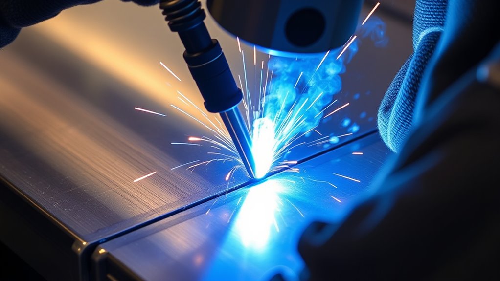
PAW is used where concentrated heat, repeatability, and controlled penetration justify the added equipment and setup effort. Suitable applications include longitudinal seams, tubing, bellows, sensor housings, instrument parts, aerospace hardware, selected medical-device components, and automated production assemblies. Actual suitability depends on the product specification and validated process—not the industry label alone.
In aerospace and high-performance manufacturing, PAW can be useful on stainless steel, titanium, and nickel alloys when the procedure, shielding, operator qualification, and inspection plan meet the applicable requirements. A concentrated arc may reduce the amount of surrounding metal heated compared with a slower, wider process, but distortion depends on total heat input, restraint, joint design, and weld sequence.
Mechanized PAW can reduce variation in torch height, travel speed, and joint tracking. That makes it attractive for repeat production. It does not make the process self-correcting: worn consumables, gas drift, fixture changes, material variation, or coolant problems can still produce repeated defects.
Manual PAW remains useful for specialized work, but its narrow process window and equipment complexity usually make it less common than TIG for general repair and fabrication.
Advantages and Limitations of Plasma Arc Welding
PAW offers important technical advantages, but the benefits depend on a compatible joint and a controlled procedure.
Main Advantages
- Concentrated arc: The constricting nozzle creates a narrow, energy-dense heat source.
- Controlled penetration: Melt-in and keyhole modes cover different fusion requirements.
- Arc-length tolerance: The stiff arc can be less sensitive than TIG to small torch-height changes within the qualified window.
- Repeatability: Mechanized motion and controlled gas circuits support consistent production welds.
- Autogenous capability: Suitable joints may be welded without filler, reducing groove volume and added material.
- Potentially lower distortion: Faster travel or a narrower heated zone may reduce distortion on a properly designed procedure.
- Low spatter: PAW uses a non-consumable electrode and can produce clean weld surfaces when setup and shielding are correct.
Main Limitations
- Higher equipment cost: The process adds a specialized torch, precise gas controls, cooling, and often automation.
- Setup sensitivity: Electrode recess, centering, nozzle wear, gas flow, and cooling must stay within a narrow range.
- Joint fit-up demands: Gaps, mismatch, thickness variation, and poor alignment can destabilize keyhole welding.
- Training requirement: Operators and technicians need process-specific instruction and qualification where required.
- Consumable maintenance: A damaged nozzle or contaminated electrode can change arc shape and penetration.
- Access limits: Torch size and nozzle geometry may not suit tight fillets, corners, or field repairs.
- Not always economical: TIG, MIG, laser, resistance welding, or another process may be simpler for the part and production volume.
Plasma Arc Welding vs TIG Welding
PAW and TIG both use a non-consumable tungsten electrode and external shielding gas. TIG exposes the electrode and uses an open arc between the electrode and workpiece. PAW places the electrode inside the torch and constricts the arc through a cooled nozzle. ESAB summarizes these process differences in its GTAW versus PAW comparison.
| Factor | Plasma Arc Welding | TIG Welding |
|---|---|---|
| Arc Shape | Constricted by a nozzle; narrow and stiff | Open arc; wider and more exposed |
| Gas System | Separate plasma and shielding-gas functions | Primarily one shielding-gas circuit |
| Penetration Modes | Microplasma, melt-in, and keyhole | Primarily melt-in fusion |
| Setup Tolerance | Tight consumable, gas, cooling, and fit-up control | Simpler torch setup but still sensitive to technique and shielding |
| Automation | Well suited to repeatable mechanized seams | Also automatable and widely available |
| Equipment Cost | Generally higher and more specialized | Generally lower and easier to source |
| Best Fit | Precision production, narrow seams, controlled or keyhole penetration | General high-quality welding, repair, varied joints, and field work |
Common Defects and Troubleshooting Tips
Use the weld appearance, sound, penetration profile, machine data, and inspection results to troubleshoot. Change one controlled variable at a time and preserve the approved procedure window.
Porosity
Porosity often points to contaminated metal, moisture, gas leaks, poor purge, insufficient shielding, excessive turbulent flow, or an unsuitable gas mixture. Check joint preparation, cylinders, regulators, hoses, torch seals, preflow, postflow, and shop drafts before changing current.
Arc Instability
An unstable or wandering arc may come from incorrect electrode recess, poor centering, a contaminated tungsten tip, a damaged nozzle, wrong plasma-gas flow, inadequate cooling, an unstable pilot arc, or a loose work connection. Shut down and inspect the torch rather than continuing until the nozzle fails.
Lack of Fusion
Lack of fusion can result from low current, excessive travel speed, poor joint preparation, torch misalignment, an incorrect work angle, excessive mismatch, or loss of keyhole stability. On mechanized seams, verify joint tracking and actual travel speed as well as programmed values.
Excessive Distortion
Distortion may result from excessive total heat input, slow travel, poor fixturing, an unbalanced weld sequence, too many repair passes, or a joint design that is unsuitable for PAW. Review current, voltage, travel speed, restraint, tack sequence, and heat distribution together.
Undercut, Burn-Through, and Keyhole Defects
Undercut or burn-through can come from excessive current, plasma-gas flow, travel speed, root gap, or torch misalignment. An open end crater may indicate that current and gas were stopped too quickly. Incomplete penetration can come from the opposite conditions or from a nozzle that no longer produces the expected arc shape.
| Symptom | Check First | Then Verify |
|---|---|---|
| Pores or pinholes | Cleanliness, moisture, leaks, purge, and shielding | Gas composition, turbulence, filler condition, and base-metal defects |
| Arc wanders | Electrode centering, recess, and nozzle condition | Work lead, plasma flow, coolant, pilot circuit, and magnetic arc blow |
| Incomplete penetration | Current, travel speed, torch centerline, and joint gap | Nozzle orifice, gas flow, thickness, fit-up, and actual machine output |
| Undercut or burn-through | Current, gas flow, speed, and root opening | Torch angle, mismatch, edge preparation, and keyhole stability |
| Heavy discoloration | Shielding and postflow | Gas purity, leaks, backing purge, drafts, and heat input |
Inspection and Preventive Maintenance
Inspect the weld to the drawing, welding procedure, and governing acceptance standard. Visual inspection should check bead profile, undercut, overlap, cracks, arc strikes, crater condition, root appearance, discoloration, and dimensional distortion. Critical work may also require liquid penetrant, radiographic, ultrasonic, leak, pressure, metallographic, or mechanical testing by qualified personnel.
Preventive maintenance keeps a qualified procedure repeatable. Track electrode life, nozzle wear, gas-filter condition, coolant conductivity and temperature, hose condition, regulator performance, work-lead resistance, and fixture wear. Record unexpected parameter drift and replace damaged parts with manufacturer-approved components.
- Inspect the electrode and nozzle at the interval specified by the torch manufacturer.
- Keep separate, clean consumables for contamination-sensitive alloys when the procedure requires it.
- Check gas lines and torch seals for leaks; never use an open flame for leak testing.
- Keep the work clamp contact area clean and secure.
- Test interlocks, flow alarms, emergency stops, and cooling-system protection.
- Lock out and isolate electrical, gas, pneumatic, and cooling energy before internal maintenance.
Essential Safety Precautions for Plasma Arc Welding
PAW exposes operators and nearby workers to ultraviolet and infrared radiation, hot metal, electric shock, fire, compressed gas, fumes, gases, and moving automation. OSHA lists welding hazards that include metal fumes, UV radiation, burns, eye injury, and electrical shock. Review its welding hazard and control guidance before developing a workplace procedure.
- Wear complete PPE: Use safety glasses with side protection, a welding helmet with the correct filter shade, flame-resistant clothing, dry welding gloves, and protective footwear.
- Control fumes at the source: Use local exhaust ventilation positioned to capture the plume without disturbing shielding gas. Outdoor work does not automatically provide adequate ventilation.
- Evaluate the material: Review the safety data sheets and coatings. Stainless steel welding can generate hexavalent chromium, while paints, platings, cleaners, and residues can create additional toxic exposures.
- Prevent oxygen displacement: Argon and helium can displace air, especially in pits, tanks, vessels, and other enclosed spaces. Follow confined-space rules and atmospheric testing requirements.
- Protect others: Install welding screens and control access so nearby people cannot view the arc or contact hot parts.
- Prevent fire: Remove combustibles, control sparks and hot metal, use permits and a fire watch when required, and keep the correct extinguisher available.
- Secure gas cylinders: Keep cylinders upright and restrained, protect valves, use the correct regulators, and separate them from damage and heat.
- Prevent electric shock: Keep gloves and clothing dry, inspect cables and insulation, use a sound work connection, ground equipment as required, and follow the manufacturer’s shutdown instructions.
- Verify cooling: Do not weld with a water-cooled torch unless coolant flow and leak protection are operating correctly.
- Control automation: Guard robot and carriage travel, use emergency stops, and prevent unexpected startup during setup or maintenance.
Minimum Lens Shades for PAW
OSHA’s eye-protection table lists minimum protective shades by PAW current. Start with a shade that is too dark to see the weld zone, then move to a lighter shade only when needed and never below the applicable minimum. Confirm employer rules and the latest equipment and consensus-standard guidance.
| PAW Arc Current | OSHA Minimum Protective Shade |
|---|---|
| Less than 20 A | Shade 6 |
| 20–100 A | Shade 8 |
| More than 100–400 A | Shade 10 |
| More than 400–800 A | Shade 11 |
See OSHA 29 CFR 1910.133 for the federal eye- and face-protection requirements and shade table. OSHA also explains that welding fumes may contain metals and process gases, and that ventilation or respiratory protection may be required in its welding fume control fact sheet.
Warning: Never weld a sealed, pressurized, previously flammable, or unknown container without a documented cleaning, testing, venting, and hot-work procedure. Never weld near chlorinated-solvent vapors or on an unidentified coating. Heat and ultraviolet radiation can create toxic gases, fire, explosion, or pressure failure.
Frequently Asked Questions
What safety precautions are essential for plasma arc welding?
Use the correct helmet shade, safety glasses, flame-resistant clothing, gloves, footwear, local exhaust ventilation, welding screens, fire controls, secured cylinders, sound electrical connections, and operating torch cooling. Evaluate coatings and alloy fumes, and follow confined-space, hot-work, lockout, and respiratory-protection rules when applicable.
How does plasma arc welding differ from TIG welding?
Both processes use a non-consumable tungsten electrode. TIG uses an open arc, while PAW constricts the arc through a cooled nozzle and normally uses separate plasma and shielding-gas functions. PAW can provide a stiff, concentrated arc and keyhole penetration, but its equipment and setup are more complex.
What materials can be welded using plasma arc welding?
PAW can be used on selected stainless steels, carbon and low-alloy steels, nickel and cobalt alloys, titanium, aluminum alloys, and copper alloys. The exact machine, polarity, gas, joint, filler, heat treatment, and procedure must be qualified for the specific alloy and service.
Is special training required to operate plasma arc welding equipment?
Yes. Operators need training in torch assembly, electrode recess, gas control, cooling, current programming, fit-up, keyhole behavior, troubleshooting, inspection, and safety. Code or customer-controlled work may also require a qualified welding procedure and documented welder or welding-operator qualification.
How do environmental factors affect plasma arc welding quality?
Drafts can disrupt shielding, while moisture, dirt, oil, coatings, contaminated gas, and unstable temperature can contribute to porosity, oxidation, arc instability, or inconsistent penetration. Protect the weld zone from uncontrolled airflow while keeping fume extraction effective.
What gas is commonly used for plasma arc welding?
Argon is common for plasma and shielding functions because it supports stable starting and control. Helium, argon-helium, or limited argon-hydrogen mixtures may be used in approved procedures. Gas selection must match the alloy, torch, polarity, mode, and welding procedure.
Is plasma arc welding good for beginners?
It is usually not the easiest first welding process. PAW adds tight torch assembly, gas, cooling, and parameter controls. A beginner can learn it through supervised training, but many welders first build puddle control and safety skills with TIG, MIG, or stick welding.
What polarity is used for plasma arc welding?
DC electrode negative is common for many PAW procedures. Aluminum and specialized applications may require equipment designed for variable-polarity or another approved waveform. Always use the polarity specified by the machine manufacturer and qualified welding procedure.
Can plasma arc welding be done manually?
Yes. Manual PAW is possible for suitable work, especially microplasma and specialized repairs. Mechanized or robotic systems are common when keyhole stability, travel speed, torch position, and production repeatability are critical.
Conclusion
Plasma arc welding is a precise fusion process built around a constricted arc, separate gas functions, a carefully assembled torch, and tightly controlled movement. Its microplasma, melt-in, and keyhole modes can handle very different jobs, from thin precision parts to suitable full-penetration seams.
The process delivers its best results when the operator follows a qualified procedure, controls electrode recess and nozzle condition, protects both sides of sensitive welds, verifies cooling and gas flow, and inspects the finished joint. PAW is not automatically better than TIG or another process, but it is a powerful choice when its concentration, penetration control, and repeatability match the part.
Sources
- Fronius — Plasma Welding Principle and System Overview — supports the constricted-arc design, separate plasma and shielding gases, and comparison with TIG.
- Haynes International — Plasma Arc Welding — supports transferred-arc PAW, melt-in and keyhole modes, DCEN guidance, gas selection, and parameter interaction for nickel- and cobalt-base alloys.
- American Welding Society — Welding Handbook Chapter on Plasma Arc Welding — identifies PAW equipment, materials, process variations, applications, procedures, weld quality, costs, and safety as core process topics.
- OSHA — Welding, Cutting, and Brazing Hazards and Solutions — supports controls for fumes, ultraviolet radiation, burns, eye injury, and electrical hazards.
- OSHA 29 CFR 1910.133 — Eye and Face Protection — provides minimum protective lens shades for plasma arc welding by current range.
- OSHA — Controlling Hazardous Fume and Gases During Welding — supports ventilation, fume control, confined-space precautions, inert-gas asphyxiation risks, and hexavalent chromium warnings.