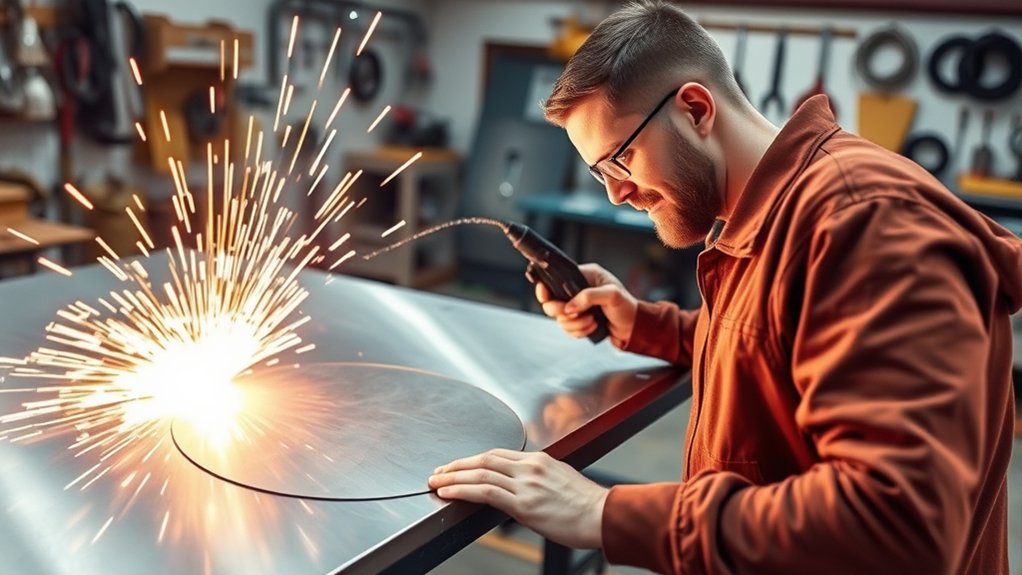
Plasma cutter speed is not one fixed number. The correct travel speed depends on the exact cutter, amperage, consumable, gas, metal, thickness, torch height, and whether the cut is handheld or mechanized. The safest way to get a clean edge is to begin with the manufacturer’s cut chart, make a short test cut, and adjust in small steps.
Quick Answer
Plasma cutting speed can range from a few inches per minute on thick plate to several hundred IPM on thin sheet. There is no universal speed chart. Use the chart for your exact machine, material, thickness, amperage, consumable, and gas, then fine-tune the setting with test cuts.
Key Takeaways
- Material thickness, amperage, consumables, gas, torch height, and machine motion all affect travel speed.
- A severance rating is a maximum-thickness capability, not a faster or cleaner cutting mode.
- Low-speed dross is usually thick and bubbly; high-speed dross is usually a smaller, hard bead with strong arc lag.
- Change one variable at a time and record settings that work for each material batch and thickness.
- Never treat a generic internet speed range as a substitute for the manufacturer’s current cut chart.
At a Glance
| Time Required | About 10–20 minutes to verify settings with scrap test cuts |
| Difficulty | Moderate; basic machine setup and cut inspection skills are required |
| Tools Needed | Plasma cutter, correct consumables, clean gas supply, work clamp, PPE, scrap coupons, and a way to measure or control travel speed |
| Cost | Usually limited to scrap material, gas, electricity, and normal consumable wear when the cutter is already owned |
Warning: Plasma cutting creates intense arc radiation, hot metal, sparks, electrical hazards, and airborne metal fumes. Read the machine manual, use suitable eye and face protection, flame-resistant clothing, hearing protection, dry gloves, fire controls, and effective ventilation before making any test cut.
Understanding Plasma Cutting Speeds

Plasma cutting speed is normally listed in inches per minute (IPM) or millimeters per minute (mm/min). The number tells you how quickly the torch should move along the programmed path or hand-cut line after the arc has pierced the workpiece.
The speed can be very high on thin sheet and very low near a machine’s maximum thickness. For example, the current Hypertherm Powermax45/65/85/105 SYNC Cut Charts Guide lists best-quality settings from 350 IPM on some thin-gauge materials down to single-digit IPM on thick plate. That spread is why a broad claim such as “plasma cutters run at 20–100 IPM” is not dependable.
Rated Cut, Recommended Cut, Production Cut, and Severance
Manufacturers use several capacity terms, and they do not mean the same thing:
- Best-quality or recommended speed: A starting setting intended to balance edge angle, dross, and surface finish.
- Highest-production speed: A faster setting intended to increase output, sometimes with a trade-off in edge quality.
- Rated cut: A manufacturer-defined capacity benchmark. Some handheld brands use 15 IPM as the reference speed for rating maximum mild-steel thickness.
- Severance cut: The thickest material the machine can separate under stated conditions. It is normally slow and requires more cleanup.
Do not confuse the 15 IPM rating convention used by some manufacturers with a universal best speed for 1/2-inch steel. Also, a severance cut does not run faster than a quality cut; it pushes the machine near its maximum thickness and usually moves much more slowly.
Note: Handheld capacity charts and mechanized cut charts serve different purposes. A CNC chart may include cut height, pierce height, delay, arc voltage, kerf width, and separate best-quality and highest-production speeds that do not apply directly to freehand cutting.
Factors Affecting Speed in Plasma Cutting
Material thickness and the selected cutting process are the first variables to check, but they are not the only ones. Two plasma cutters set to the same amperage can use different speeds because their torches, nozzles, gas delivery, arc characteristics, and cut charts differ.
Material and Thickness
Thicker metal normally requires slower travel because the arc must remove molten material through a deeper kerf. Material type also changes the result, but there is no safe rule that aluminum is always faster than mild steel or that stainless is always slowest. On one current 45-amp air-plasma chart, 1/2-inch aluminum is faster than mild steel, while other thicknesses and processes show different relationships. Use the chart instead of relying on melting point or thermal conductivity alone.
Amperage and Consumable Size
A higher-amperage process can support faster cutting or greater thickness, but more amperage is not automatically better. Oversizing the nozzle or current for thin material can widen the kerf, increase bevel, and reduce detail. Choose the cartridge, nozzle, and amperage range specified for the material thickness.
Gas Type, Pressure, and Air Quality
Gas selection changes arc energy, cut chemistry, edge finish, and speed. According to Hypertherm’s plasma gas selection guidance, clean, dry air is versatile for mild steel, stainless steel, and aluminum, while oxygen is commonly used on mechanized mild-steel systems for high speed and clean edges. Nitrogen, F5, argon-hydrogen, and water-shield processes are application-specific and must be supported by the equipment.
Moisture, oil, dirt, low pressure, restricted flow, or an undersized compressor can weaken the plasma jet and make a correct chart speed behave like an excessive speed. Fix the gas supply before changing travel speed.
Torch Height, Angle, and Work Lead
There is no universal 1/8-inch standoff for every torch. Some handheld consumables are designed for drag cutting, while mechanized processes use a charted cut height and a higher initial pierce height. Hypertherm’s torch-height guidance explains that arc voltage is used on mechanized systems to maintain the specified torch-to-work distance.
Keep a handheld torch square to the work unless the manual calls for a lead angle. Attach the work clamp to clean metal with a secure connection. A poor work connection can cause unstable transfer and misleading cut symptoms.
Consumable Condition, Motion, and Duty Cycle
A worn or damaged nozzle changes the arc shape and can create bevel or dross even when the programmed speed is correct. On CNC equipment, loose mechanics, poor acceleration, vibration, and inaccurate torch-height control can also make the actual path speed differ from the commanded speed. Long cuts may be limited by the power source duty cycle, so check the manual before planning continuous production.
Comparing Plasma Cutting Speeds to Other Methods
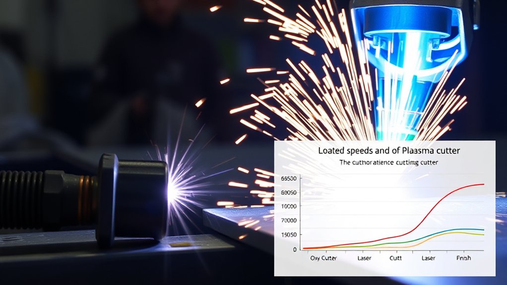
Plasma is generally faster than oxy-fuel on thin and medium carbon-steel plate, and it can cut conductive metals that ordinary oxy-fuel cutting cannot, including stainless steel and aluminum. Oxy-fuel remains useful for very thick carbon steel, heating, and work where low equipment cost or multiple torches matter.
Laser usually has the advantage on thin sheet, tiny features, and the narrowest kerf. Modern high-definition plasma becomes especially competitive as plate gets thicker. Hypertherm’s current comparison guidance places plasma’s strongest speed and cost advantage over fiber laser at roughly 12–16 mm (about 1/2–5/8 inch) and above, but the crossover depends on laser power, plasma amperage, material, assist gas, feature size, and required tolerance.
Do not compare the processes with one fixed IPM or kerf number. A valid comparison must use the same metal, thickness, part geometry, quality target, piercing requirements, machine class, and operating conditions.
The correct plasma speed is the fastest setting that still produces full penetration, acceptable bevel, manageable dross, and the edge quality the job requires.
How Cutting Speed Changes Cut Quality
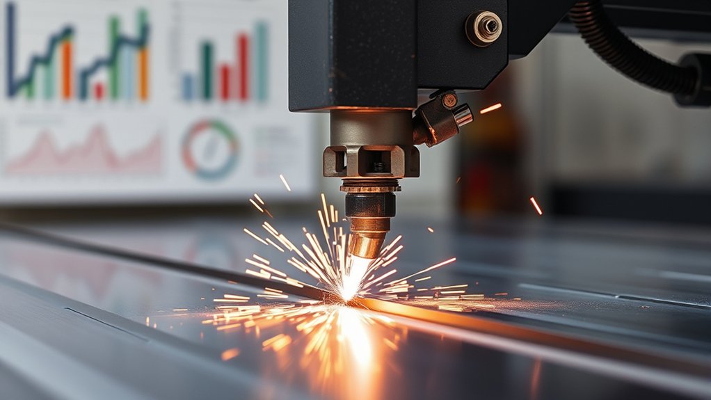
Travel speed changes arc lag, kerf shape, dross, heat input, and edge angle. Moving faster can reduce heat input only while the arc still penetrates cleanly. Once the torch outruns the process, the edge gets worse instead of better.
| Condition | What You May See | First Adjustment |
|---|---|---|
| Too slow | Wide kerf, rounded top edge, heavy top spatter, and thick bubbly low-speed dross | Increase speed in small steps after confirming amperage and height |
| Correct range | Full penetration, small manageable dross, stable sparks below the plate, and acceptable bevel | Keep the setting and record it for the same setup |
| Too fast | Strong trailing arc, sparks spraying backward or upward, incomplete penetration, bevel, and a narrow hard bead of high-speed dross | Reduce speed in small steps and inspect the nozzle and standoff |
At extremely low speed, the transferred arc can extinguish because it no longer has enough new metal to cut. At extremely high speed, the arc may fail to penetrate or become unstable. Hypertherm recommends correcting dross by checking consumables and changing speed in small increments rather than making large, random adjustments.
Example Plasma Cutter Speed Chart
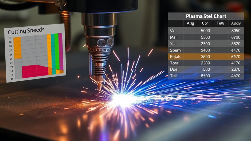
The following numbers are model-specific examples from the June 2024 Powermax45 SYNC mechanized cut charts using a 45-amp standard cartridge and air. They are not universal settings for every 45-amp plasma cutter.
| Material | Thickness | Best Quality | Highest Production |
|---|---|---|---|
| Mild steel | 10 gauge | 95 IPM | 181 IPM |
| Mild steel | 1/4 inch | 46 IPM | 74 IPM |
| Mild steel | 3/8 inch | 33 IPM | 38 IPM |
| Mild steel | 1/2 inch | 18 IPM | 24 IPM |
| Stainless steel | 1/4 inch | 30 IPM | 59 IPM |
| Stainless steel | 1/2 inch | 12 IPM | 19 IPM |
| Aluminum | 1/4 inch | 70 IPM | 104 IPM |
| Aluminum | 1/2 inch | 21 IPM | 26 IPM |
These chart values were developed with new consumables and specified power, gas, and site conditions. The guide describes best-quality speed as the starting point for the best angle, least dross, and best surface finish. Its highest-production settings can be roughly 20%–30% faster on many processes, but they do not always produce the best edge.
Products Worth Considering

The suitable plasma torch: Plasma spring guide AG60 / SG55 WSD60 plasma cutting torch
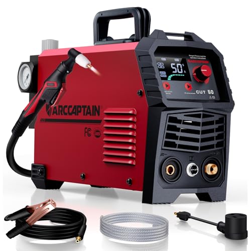
【Powerful Cutting Ability】Switch effortlessly between 110V and 220V for home or workshop use. Achieve professional 1/2" clean cuts on steel, aluminum, and copper with advanced LGBT technology. Perfect for DIY projects and heavy-duty tasks. Recommended maximum cutting thickness: 12mm @ 35A / 110V / 55 PSl; 18mm @ 50A / 220V / 75 PSI. Note: Requires compressed air (compressor sold separately).

[Achieve Precise Cuts] PT31 Plasma Cutting Consumables – Your Essential Tool for Efficient Cutting! Whether you're working with sheet metal, steel, or any other material, superior cutting performance ensure clean, accurate, and smooth cuts.
How to Read a Manufacturer Cut Chart
- Match the exact system and torch. Do not use a chart for a different model just because the amperage is similar.
- Select the material and thickness. Confirm gauge conversions because sheet gauge varies by metal type.
- Install the listed consumable. Fine-feature, drag, mechanized, and high-amperage consumables use different parameters.
- Use the specified gas and pressure. Clean, dry air is essential on air-plasma systems.
- Enter cut height, pierce height, and delay. These are separate settings on mechanized systems.
- Start with best-quality speed. Move toward production speed only after the edge meets the job’s requirements.
- Apply the listed arc voltage only with a compatible torch-height control. Adjust voltage to maintain physical height, not as an independent speed cure.
Common Mistakes With Cutting Speed
The most common mistake is changing speed before confirming the rest of the setup. A worn nozzle, wet air, incorrect cartridge, poor work connection, wrong torch height, or low gas flow can imitate a speed problem.
Incorrect Speed Consequences
When the torch is too slow:
- Low-speed dross builds up. The bottom edge develops a thick, porous, or bubbly deposit.
- The kerf widens. Excess heat and a broad arc can round the top edge and increase distortion.
- Top spatter increases. Molten metal can collect along the top surface.
- The arc may eventually extinguish. At an extreme, there is not enough fresh metal entering the arc to sustain the transferred cut.
When the torch is too fast:
- Penetration becomes incomplete. Sparks may spray backward or upward instead of exiting below the plate.
- The arc lags hard behind the torch. The cut face develops excess bevel and a narrow kerf.
- High-speed dross forms. A small, hard bead can cling to the bottom edge and be difficult to remove.
- Corner and hole quality falls. The motion system may not maintain the commanded speed through small features.
Balancing Speed and Quality
Start with the manufacturer’s best-quality values. Inspect the cut before chasing a faster cycle time. If output matters more than finish, test the production setting and measure whether the extra cleanup, bevel, or dimensional change is acceptable.
Change one variable at a time. If speed, amperage, height, and pressure all change together, you will not know which adjustment helped. Hypertherm’s plasma cutting mistake guide identifies cutting too fast or too slow as a major source of dross and kerf problems.
Material-Specific Speed Adjustments
- Mild steel: Air works well on portable systems, while mechanized oxygen processes can improve speed and edge quality when the system supports them.
- Stainless steel: Use the chart for the specified air, nitrogen, F5, or multi-gas process. Gas choice changes color, oxidation, dross, and speed.
- Aluminum: Use approved air, nitrogen, or multi-gas settings. Do not assume that the same thickness always runs faster than steel.
- Copper and brass: Confirm that the machine manufacturer provides a supported procedure. Conductive nonferrous metals may require system-specific testing and adequate power.
How to Dial In the Best Plasma Cutting Speed
- Identify the metal and measure its true thickness. Remove scale only where the work clamp and height sensing require clean contact.
- Open the current manual or cut chart for the exact machine. Select material, thickness, process, gas, amperage, and consumable.
- Inspect and install the correct consumables. Replace a nozzle with an enlarged, notched, or oval orifice.
- Verify the gas supply. Confirm the required flow and pressure, drain moisture, and make sure filters are serviceable.
- Set the torch correctly. For CNC work, enter the listed cut height, pierce height, delay, and initial arc voltage. For handheld work, use drag or standoff technique only as directed by the manual.
- Begin at the best-quality speed. Make a straight test cut on scrap from the same material batch.
- Read the cut. Check penetration, spark direction, lag lines, bevel, top rounding, kerf, and dross.
- Adjust in small steps. A 5 IPM change is useful for many medium-speed processes; use smaller percentage changes when the chart speed itself is low.
- Repeat and record. Save the final speed with the amperage, consumable, gas, pressure, cut height, material grade, and thickness.
Pro Tip: Tune long straight cuts first. Small holes, sharp corners, and short contours involve acceleration limits and may need separate CNC rules instead of one global speed reduction.
Products Worth Considering

Package Include: 10 Shield Cups, 50 Nozzles, 20 Swirl Baffle, and 30 Electrodes.

High-Quality Material:Made of high quality material to ensure a longer lifespan and superior performance.

10 pcs TIPS (Extended) /10 pcs ELECTRODE (Extended) /10 pcs SHIEDED-CUP/10 pcs GAS RING
Handheld Speed Control
For freehand cutting, brace your body, use a straightedge or template when possible, and move continuously. Watch the sparks below the plate without placing your face in the fume plume. If sparks trail sharply backward, slow down. If the torch dwells and creates a wide molten slot, speed up after confirming full penetration.
CNC Holes, Corners, and Small Features
A CNC table may command the correct straight-line speed but slow heavily in a small circle or corner. Too much slowdown increases dross and taper. Use the table manufacturer’s hole-cutting rules, lead-ins, lead-outs, acceleration settings, and torch-height lockout features. Do not copy straight-cut speed directly into every small-feature toolpath.
Plasma Cutting Safety Before You Test Speed
Speed tuning still involves live cutting, so treat every test coupon as hot work. OSHA identifies metal fumes, ultraviolet radiation, burns, eye injury, electrical shock, and fire as major welding and cutting hazards. Its welding, cutting, and brazing guidance recommends suitable work practices, ventilation, and personal protective equipment.
- Ventilate the breathing zone. Plasma cutting melts metal and produces airborne fumes. Stainless steel, galvanized steel, painted metal, and coated parts may require stronger controls and a formal exposure assessment.
- Protect eyes and skin. Use the lens shade and protective clothing required by the machine manual and applicable safety rules.
- Control fire hazards. Clear combustibles, keep an appropriate extinguisher nearby, and account for sparks traveling through gaps or to lower levels.
- Keep the system dry and grounded. Do not handle the workpiece or service consumables while the circuit is energized.
- Do not cut unknown containers. Tanks, drums, and closed vessels can contain flammable or toxic residues even when they appear empty.
- Use only approved gases. Never improvise with oxygen or a fuel gas in a system not designed for it.
Warning: Aluminum cutting near water can create an explosion hazard if hydrogen accumulates. Do not cut aluminum alloys underwater or on a water table unless the table and ventilation system are designed for it and a qualified risk-control plan prevents hydrogen buildup. Never cut aluminum-lithium alloys in the presence of water.
Frequently Asked Questions
Can plasma cutters cut underwater without a speed reduction?
Sometimes, but not as a universal rule. Certain automated systems can use the same chart speed underwater for some materials and thicknesses, while other processes require a reduction or an air curtain. Follow the underwater cut chart for the exact system. Aluminum and hydrogen-containing gases add serious explosion hazards near water.
How does plasma cutter speed vary with different gases?
Gas changes arc energy, chemistry, dross, edge finish, and travel speed. Oxygen is widely used for fast, clean mechanized mild-steel cutting. Air is versatile and economical. Nitrogen, F5, argon-hydrogen, and water-shield processes are used for specific stainless-steel or aluminum applications. Use only gases and settings approved by the manufacturer.
Are there speed limitations for handheld plasma cutters?
Yes. A handheld operator must maintain a steady torch angle, distance, and travel rate, which becomes difficult at very high or very low speeds. Use guides when possible and do not assume a mechanized chart can be followed accurately by hand.
How does operator skill affect plasma cutting speed?
Skill affects how consistently a handheld torch follows the line, remains square, and maintains the required distance. An experienced operator can hold the charted range more closely and recognize bad spark direction, dross, or incomplete penetration before wasting a full part.
Does ambient temperature affect plasma cutter speed?
Ambient temperature is usually not the first travel-speed variable to change while the machine remains within its rated operating range. Heat can reduce duty cycle, while cold and humidity can affect condensation and compressed-air quality. Follow the operating limits in the manual and correct power or gas problems before changing speed.
What speed should I use for 1/2-inch mild steel?
Use the chart for your exact cutter. As one model-specific mechanized example, Hypertherm lists 18 IPM for best quality and 24 IPM for highest production on 1/2-inch mild steel with a Powermax45 SYNC at 45 amps using air. Another machine may require a different setting.
How can I tell that I am cutting too fast?
Common signs include sparks spraying backward or upward, a strongly trailing arc, incomplete penetration, a narrow kerf, excess bevel, and a small hard bead of dross along the bottom. Check nozzle wear and torch height, then reduce speed in small steps.
Should I adjust amperage or speed first?
Start with the charted consumable and amperage, then tune speed. Change amperage only within the approved range and without exceeding the consumable rating. If the charted setup cannot produce a clean cut, inspect gas supply, consumables, work connection, and torch height before adding current.
Conclusion
Plasma cutting speed is a system setting, not a universal rule. Begin with the current chart for your exact power source, torch, consumable, gas, material, and thickness. Distinguish best-quality, production, rated-cut, and severance values. Then make a short test cut, inspect penetration and dross, adjust one variable at a time, and record the successful setup.
Faster is useful only when the edge still meets the job’s needs. Clean gas, sound consumables, correct torch height, stable motion, and safe work practices matter just as much as the IPM number.
Sources
- Hypertherm Powermax45/65/85/105 SYNC Cut Charts Guide — model-specific speeds, cut heights, pierce settings, kerf widths, and chart definitions.
- Hypertherm: 10 Common Plasma Arc Cutting Mistakes — symptoms of cutting too fast or too slow.
- Hypertherm Plasma Gas Selection Guide — gas choices for mild steel, stainless steel, and aluminum.
- Hypertherm Torch Height Control Guide — cut height, pierce height, and arc-voltage control.
- Hypertherm: Cutting Aluminum on a Water Table — hydrogen-accumulation and aluminum-water safety.
- OSHA Welding, Cutting, and Brazing Hazards and Solutions — fume, radiation, burn, electrical, and PPE hazards.