Welding subframe connectors can make an older unibody car feel tighter and more predictable, but the job is only safe when the connector kit, vehicle structure, support method, and weld procedure all agree. Treat this as structural fabrication, not a casual patch. Read the kit instructions first, support the car exactly as specified, expose sound bare steel, control fire hazards, test your welder on matching scrap, and weld only the locations shown by the connector manufacturer.
Quick Answer
To weld subframe connectors, support the car in the position required by the kit, remove nearby fire and electrical hazards, grind every weld zone to sound bare steel, test-fit and clamp both connectors, tack them, recheck body alignment, then complete the specified weld pattern. Inspect, prime, seal, and repaint every exposed area afterward.
Key Takeaways
- Use the instructions for your exact connector kit and vehicle. Weld locations, support points, gaps, and reinforcement plates are not universal.
- Keep the body level and unstressed. Many kits call for the car’s weight to be on the tires or supported under suspension or chassis points named by the manufacturer.
- Do not weld over rust, paint, undercoating, seam sealer, or weak floor metal. Repair damaged structure first.
- Remove carpet and nearby combustibles, protect fuel and brake lines, disconnect vehicle power as the service manual directs, and maintain a fire watch after welding.
- Tack first, verify fit and door gaps, then follow the kit’s exact weld pattern. More weld is not always better.
- Restore corrosion protection with compatible primer, seam sealer, topcoat, and cavity protection where needed.
At a Glance
| Time Required | About 3 to 7 hours for a clean, underfloor weld-in kit; rust repair, custom fitting, or through-floor designs can take much longer |
| Difficulty | Advanced DIY for an experienced welder; professional installation is the safer choice if the floor is rusty, thin, repaired, or made from unfamiliar high-strength material |
| Tools Needed | Kit-specified MIG or TIG welder, grinder, wire wheel, clamps, measuring tools, rated ramps, stands, or drive-on lift, welding PPE, fire-resistant blankets, lighting, and fire extinguisher |
| Cost | The connector kit, gas, wire, abrasives, coatings, and shop labor vary widely by vehicle, region, rust condition, and connector design; get a vehicle-specific quote |
Before You Weld: Confirm the Kit and Vehicle Are Suitable
This guide is mainly for aftermarket weld-in connectors on older mild-steel unibody cars. It is not a universal procedure for repairing a damaged removable subframe, engine cradle, suspension crossmember, rocker reinforcement, or modern crash structure. Those parts may use aluminum, high-strength steel, or ultra-high-strength steel that can lose strength when heated.
Start with the connector manufacturer’s instructions and the vehicle’s service or body-repair information. Confirm the correct part number, right and left sides, transmission and exhaust clearance, convertible bracing, seat-brace hardware, fuel-line routing, and every required reinforcement plate. Do not copy a weld pattern from a different car simply because the connectors look similar.
Note: A weld-in subframe connector installation is different from repairing a bent or cracked factory subframe. If the factory component is damaged, follow the OEM procedure. Some manufacturers require replacement rather than welding or heating the part.
Why You Need Subframe Connectors for Your Car’s Stability
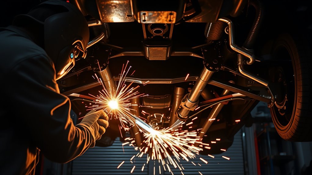
Many unibody performance cars have separate front and rear rail sections joined by a comparatively thin floor structure. A well-designed connector bridges those sections and adds a stiffer load path through the body. This can reduce unwanted twist during acceleration, braking, cornering, and lifting.
Reduced chassis flex may improve steering response, suspension consistency, door fit, body-gap stability, and the way the car reacts to higher torque, sticky tires, or firmer suspension parts. The improvement depends on the vehicle, connector design, metal condition, and weld quality. A connector cannot compensate for rotten rails, cracked torque boxes, damaged rocker structures, or poor previous repairs.
Some designs also tie into seat braces, rocker reinforcements, or other floor structures. Through-the-floor connectors may provide a more direct structural path, but they require cutting and interior fabrication. Underfloor connectors are less intrusive, while bolt-in kits are easier to install but may not provide the same permanent connection as a correctly welded kit.
A subframe connector is only as strong as the metal, fit, and welds that attach it to the car.
What Tools Do You Need for Welding Subframe Connectors?
Good lighting, stable vehicle support, clean metal, and strong clamping matter as much as the welder. Gather everything before you raise the car so you do not have to improvise while the connectors are partly fitted.
Products Worth Considering

COMPATIBILITY: Designed for Lincoln Magnum 100L (K530 series) and Tweco Mini/#1 welding torches. This kit is also a direct fit for YESWELDER FLUX-135PRO Old Version/MIG-140DS PRO/YWM-160/MIG-165DS PRO/MIG-185DS PRO/MIG-205DS PRO/MIG-250PRO/MCT-520.

220W Rapid Heating:The plastic welding machine has a power of 220 watts and a 110V-US plug, which has higher output current and faster heating speed. Using heat to embed nails or plastic rods into plastic will not cause damage to the car or plastic surface, and is very sturdy. Not only are there two repair methods to choose from: welding rods and hot nails, but there is also an overheat protection device to ensure your safety
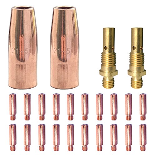
Mig Welding gun accessory 0.035" kit with contact tip,gas nozzle,gas diffuser for Lincoln Magnum 100L & Tweco Mini/#1.
Essential Welding and Fitting Tools
| Tool | Purpose |
|---|---|
| Kit-approved MIG or TIG welder | Joins the connector, reinforcement plates, and vehicle structure using the process required by the kit. |
| Angle grinder with flap disc and wire wheel | Removes paint, powder coat, rust, seam sealer, and undercoating without deeply gouging thin factory metal. |
| C-clamps, locking pliers, and pole or screw jacks | Holds the connector and plates tightly against the intended contact surfaces. |
| Straightedge, tape measure, marker, and level | Checks side-to-side placement, fore-and-aft alignment, body attitude, and weld locations. |
| Rated ramps, stands, or drive-on lift | Supports the vehicle at the exact points and attitude required by the connector instructions. |
| Scrap steel matching both thicknesses | Lets you confirm wire speed, voltage, travel, penetration, and burn-through risk before touching the car. |
MIG Wire, Gas, and Machine Setup
Many mild-steel connector kits specify gas-shielded MIG welding because it is controllable, productive, and practical under a car. Some kits allow TIG, while others specifically require MIG. Follow the kit first.
For mild-steel automotive work, ER70S-6 solid wire and a 75% argon/25% carbon-dioxide shielding mix are common choices. A 0.023- or 0.024-inch wire can make thin factory sheet easier to control, while 0.030-inch wire covers a broader range that may include thicker connector tubing. The correct choice still depends on the thinnest vehicle metal, connector thickness, joint type, machine output, and manufacturer instructions.
Use the polarity listed for the wire, confirm gas flow with the torch triggered, trim the liner and contact tip correctly, and keep the work clamp on clean metal close to the weld area. Do not copy another person’s voltage and wire-speed numbers without testing. Extension-cord length, input voltage, machine design, wire diameter, and joint position all change the result.
Safety Equipment Necessities
- Auto-darkening welding helmet: Use a suitable shade and keep clear safety glasses underneath.
- Flame-resistant gloves and clothing: Cover your neck, arms, torso, legs, and feet. Overhead sparks find gaps quickly.
- Grinding protection: Wear safety glasses, a face shield, and hearing protection when grinding or wire-wheeling.
- Ventilation: Remove coatings before heating them and use local exhaust or strong cross-ventilation that does not disturb shielding gas.
- Fire protection: Keep a suitable extinguisher within reach and use fire-resistant blankets or shields around lines, hoses, glass, upholstery, and wiring.
- Dedicated fire watch: Have another person watch the interior and hidden side of the floor during welding and continue checking for smoldering material after the last arc.
Warning: Heat and sparks can pass through floor seams and ignite carpet, jute padding, seam sealer, sound deadener, wiring, fuel vapor, or undercoating that you cannot see from below. Remove or positively shield the hazards, keep an extinguisher ready, and monitor the area for at least 30 minutes after welding.
Preparation and Finishing Materials
Keep a degreaser that leaves no residue, clean shop towels, weld-through coating approved for the planned joint, rust-inhibiting or epoxy primer, seam sealer, chassis topcoat, and cavity wax ready. Follow each coating’s technical data sheet for surface preparation, drying time, topcoating, and whether it can remain in the direct weld zone.
Weld-through primer is mainly for inaccessible mating surfaces between overlapping pieces. It does not replace cleaning, final primer, seam sealer, paint, or cavity protection. Some products instruct you to remove the coating from a MIG plug-weld site for the best result, so do not spray every bare area and assume you can weld through any thickness of coating.
How to Prepare Your Car for Subframe Connector Installation
Support the Vehicle Without Twisting the Body
Place the car on a hard, level surface and use a drive-on lift, rated wheel ramps, or rated stands at the points named by the connector manufacturer. Some instructions call for the tires to carry the car’s weight. Others allow stands under the rear axle housing and front suspension or crossmember points. The goal is to keep the body in its normal, untwisted attitude while still giving you safe access.
Set the parking brake when appropriate, chock the wheels that remain on a rolling surface, and verify that every support is stable before getting underneath. Never work under a vehicle held only by a hydraulic jack.
Before fitting the connectors, measure from repeatable chassis points, check that the rocker panels appear level, and open and close the doors. Record any existing uneven gaps so you do not mistake an old body problem for an installation problem.
Pro Tip: Take clear photos of the support points, fuel and brake line routing, door gaps, and connector position before the first tack. They give you a fast reference if anything moves or must be reassembled later.
Remove Fire, Electrical, and Line Hazards
Remove seats, carpet, underlay, sound deadener, trim, and wiring from the hot side of the floor as needed. Unclip or move fuel and brake lines only as the service information and kit instructions allow. Protect anything that cannot be removed with a metal shield and fire-resistant blanket, while leaving enough room to see whether heat is reaching it.
Turn the ignition off and follow the vehicle service manual for battery disconnection, memory retention, supplemental-restraint precautions, and module protection. Keep the welding return path short by attaching the work clamp to clean metal near the weld. Do not place the clamp so welding current must travel through bearings, hinges, control modules, or sensitive electrical connections.
Hybrid, battery-electric, fuel-cell, and some late-model vehicles add high-voltage and pyrotechnic hazards. Do not begin structural welding on those vehicles without the exact OEM depowering and repair procedure and the qualifications required for that system.
Clean and Inspect Every Welding Area
Degrease first so the grinder does not spread oil into the metal. Then remove paint, powder coat, rust, undercoating, seam sealer, galvanizing, and debris from each marked weld zone until you reach clean, sound metal. Clean the connector at every specified weld location too.
Inspect the front and rear rails, floorpan, seat braces, torque boxes, rocker reinforcements, and previous repairs. Pitting, pinholes, cracks, delamination, or metal that collapses under light probing must be repaired before the connector goes on. Welding a strong tube to weak sheet metal only moves the failure point.
Dry-fit the connector after cleaning. If the floor or rail was bent by improper jacking, correct it only as the connector and vehicle instructions permit. Do not force the connector into place with welding heat.
Step-by-Step Guide to Welding Subframe Connectors
- Read and inventory the kit: Identify the right and left connectors, front and rear ends, seat braces, plates, spacers, fasteners, and vehicle-specific steps. Stop if any required piece is missing.
- Stabilize the car: Support it at the kit-specified points, level it, chock it, and check the doors and body gaps before welding.
- Make the area fire-safe: Remove interior combustibles, protect or move fuel and brake lines, disconnect vehicle power as directed, position a fire watch, and place an extinguisher within reach.
- Inspect and repair the structure: Clean enough area to judge the metal. Repair rust, cracks, thin sections, or damaged mounting points before fitting the connector.
- Test-fit both sides: Position the connectors against the intended rails and braces. Confirm right-to-left orientation, exhaust and driveline clearance, seat hardware, parking-brake cables, and line routing.
- Mark every weld zone: Trace only the areas shown in the instructions. If a kit specifies a maximum gap, use that value. A 1/8-inch gap appears in some kit instructions, but it is not a universal standard.
- Prepare bare metal: Remove coatings from the marked weld zones on the vehicle and connector. Apply compatible weld-through coating only to hidden mating surfaces and only as the kit and coating data sheet direct.
- Clamp the connector tightly: Use clamps, locking pliers, or support jacks to close the joint without distorting the floor. Custom-fit tabs or plates as instructed rather than bridging a poor fit with oversized weld metal.
- Test the welder on coupons: Reproduce the joint using scrap close to the factory metal and connector thickness. Check for stable arc behavior, fusion into both pieces, and no burn-through. Break or cut test coupons when practical so appearance is not your only test.
- Tack in the specified sequence: Place small tacks at the front, rear, braces, and plates in the order shown by the manufacturer. Do not fully weld one end before confirming the entire connector still fits.
- Recheck alignment: Confirm the connector location, support stability, door operation, body gaps, line clearance, and exhaust clearance. Cut the tacks and reposition the part if anything is wrong.
- Complete the required weld pattern: Weld the locations, lengths, and directions shown in the kit instructions. Use short, controlled passes where heat management is needed, alternate between separated areas, and allow brief cooling periods. Bias the arc toward the thicker connector only enough to obtain fusion, then wash into the thinner vehicle metal without dwelling on it.
- Do not add unapproved welds: Avoid welding across end caps, bending-load paths, drain holes, or areas the manufacturer leaves unwelded. Do not preheat mild-steel connectors unless the exact procedure calls for it.
- Let the assembly cool naturally: Do not quench the welds with water or compressed air. Keep watching the interior, seams, and hidden cavities for smoke or smoldering material.
- Inspect, finish, and reassemble: Repair unacceptable defects, clean the weld area, restore primer, seam sealer, topcoat, and cavity protection, then reinstall all lines, clips, heat shields, interior parts, and battery connections.
Warning: Do not grind structural welds flush for appearance unless the connector manufacturer specifically requires it. Aggressive grinding can thin the weld throat, remove fusion at the toes, and weaken the surrounding sheet metal.
Welding Challenges and How to Solve Them
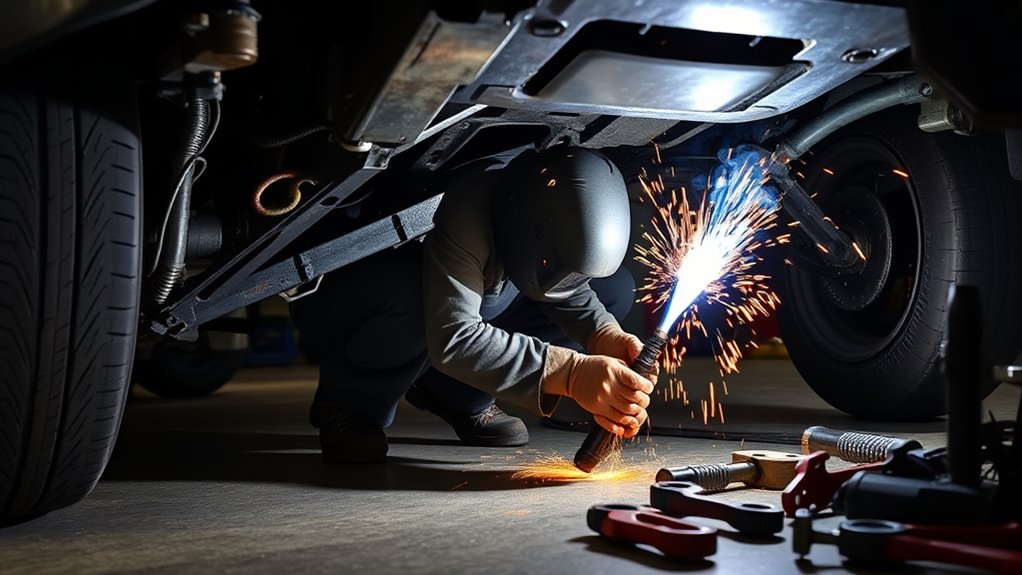
The connector tube is often thicker than the factory floor or rail, so the joint can burn through on one side while remaining cold on the other. Fit-up, torch position, clean metal, and a tested machine setup are more important than making a wide bead.
| Problem | Likely Cause | How to Fix It |
|---|---|---|
| Porous or dirty welds | Paint, rust, primer buildup, oil, undercoating, wind, or poor gas coverage | Stop, grind to clean metal, check gas flow and leaks, shield drafts, and retest on scrap. |
| Burn-through on the floor or rail | Too much heat, long dwell time, oversized wire, weak metal, or a large gap | Stop and reassess metal condition. Reduce heat input, shorten the arc-on time, improve fit, use suitable wire, and direct more of the arc toward the thicker connector. |
| Cold lap or lack of fusion | Low voltage or wire speed, fast travel, poor torch angle, dirty metal, or an underpowered machine | Grind out the defective section, correct the setup on coupons, and confirm the welder can handle the connector thickness and joint position. |
| Connector will not sit tight | Wrong side, bent floor, coating buildup, interference, or missing kit-specific trimming | Recheck orientation and instructions, remove interference, correct damaged metal, and custom-fit only the tabs or areas the manufacturer allows. |
| Doors or body gaps change | The car shifted, a support settled, or the body was twisted when tacked | Stop welding. Verify support points and level, compare the pre-weld measurements, and remove tacks if necessary before continuing. |
| Heavy smoke or burning odor | Hidden seam sealer, carpet padding, cavity wax, wiring, or undercoating is heating | Stop immediately, inspect both sides and cavities, extinguish any ignition, remove more material, improve shielding, and do not resume until the area is fire-safe. |
| Cracking near a weld later | Wrong weld location or direction, poor fusion, stress concentration, over-welding, or excessive grinding | Stop driving aggressively, inspect the surrounding structure, and have the repair reviewed against the kit and vehicle procedure by a qualified fabricator. |
Note: Some kits require continuous welds in selected areas, some call for stitch welds, and some use plug welds, plates, or seat braces. Follow the drawing for your kit rather than applying one pattern everywhere.
How to Inspect the Welds Before Coating
Let the assembly cool enough to inspect safely, then use bright light and a mirror to view every side you can reach. A sound-looking weld should tie into both pieces without obvious cracks, long undercut, open pinholes, missed edges, or metal rolled over the joint without fusion.
Check the beginning and end of each required weld, the corners of reinforcement plates, brace legs, plug welds, and any areas partly hidden by the floor. Compare the completed work with the manufacturer’s photos and weld map. Do not assume a smooth bead is strong. If you cannot judge penetration or the vehicle metal kept burning away, stop and have the work inspected by an experienced structural or motorsports fabricator.
After the visual check, confirm that the doors, seats, exhaust, parking-brake cables, fuel and brake lines, and suspension components still clear and operate correctly. Verify that no line clip, heat shield, fastener, or drain path was left loose or blocked.
Post-Welding Care for Your Subframe Connectors
- Finish the fire watch: Inspect the interior, underbody, seams, and cavities repeatedly for smoke, heat, or odor for at least 30 minutes after the last weld, and longer when hidden combustible material may remain.
- Repair defects before coating: Grind only enough to expose a confirmed defect, then reweld using the corrected setup. Do not cosmetically flatten acceptable structural welds.
- Clean the area: Remove spatter, loose scale, grinding dust, soot, and residue without thinning the weld or vehicle metal.
- Prime exposed steel: Apply a compatible rust-inhibiting or epoxy primer to all accessible bare steel according to the product instructions.
- Seal panel overlaps: Apply automotive seam sealer where the original construction or connector design needs it. Do not cover drain holes.
- Apply topcoat and cavity protection: Use a durable chassis coating outside and cavity wax inside enclosed rails or overlaps when appropriate.
- Restore every removed item: Refit line clips, wiring retainers, heat shields, seats, carpet, braces, and hardware. Reconnect the battery and initialize systems according to the service manual.
- Reinspect after use: Check the welds, coatings, nearby lines, fasteners, and clearances after the first short drive and during normal underbody inspections, especially on cars exposed to rain, road salt, track use, or hard launches.
Choosing Weld-In, Bolt-In, or Through-the-Floor Connectors
| Connector Type | Main Advantage | Main Limitation |
|---|---|---|
| Bolt-in | No welding and easier removal | Performance depends on the kit, fastener clamping, hole condition, and regular hardware inspection. |
| Underfloor weld-in | Permanent connection with limited interior cutting | Requires safe overhead welding, sound factory rails, careful line protection, and full corrosion restoration. |
| Through-the-floor | Can create a direct structural path and integrate with cages or reinforced floors | Requires cutting, interior fabrication, sealing, and more advanced planning. It may affect seating, carpet, and ground clearance. |
Choose the design made for your exact vehicle and intended use. A street car with an intact floor may need a different solution from a convertible, drag car, road-race build, or car with a roll cage. Connector design, attachment area, and installation quality matter more than the label alone.
Products Worth Considering

BBK is your Number One Aftermarket Performance Brand in the USA - American Designed and Built

BBK is your Number One Aftermarket Performance Brand in the USA - American Designed and Built

BBK is your Number One Aftermarket Performance Brand in the USA - American Designed and Built
Frequently Asked Questions
Can a car subframe be welded?
An aftermarket connector may be designed to weld to specific unibody rails, but that does not mean every damaged factory subframe or suspension cradle is repairable by welding. Materials and crash functions vary. Follow the OEM body-repair procedure for the damaged part; some subframes must be replaced rather than heated or repaired.
What is the best welder for subframe connectors?
Use the process required by the connector manufacturer and a machine with enough output and duty cycle for the thickest part of the joint while still controlling the thin factory metal. Gas-shielded MIG is common for mild-steel kits. Do not choose a welder only by brand or input voltage; verify its rated thickness range and prove the setup on matching coupons.
Can you use flux-core wire for subframe connectors?
Only use it if the kit manufacturer permits it and the wire, machine, joint, and operator are suitable. Self-shielded flux-core usually creates more smoke and spatter and can be harder to control on thin factory sheet. Many connector instructions call for gas-shielded MIG, and some specifically require it.
Are subframe connectors worth it?
They can be worthwhile on many older unibody performance cars, convertibles, high-torque builds, and cars with sticky tires or firm suspension. A correctly designed and installed kit may reduce flex and improve consistency. It will not fix rust, cracked mounting points, poor alignment, or damaged structure.
How much does it cost to weld subframe connectors?
There is no dependable flat price. Labor changes with the vehicle, kit design, rust, interior removal, exhaust interference, surface preparation, coating work, and local shop rates. Ask for a quote that states whether fitting, rust repair, line protection, seam sealing, paint, and reassembly are included.
Should subframe connectors be welded with the suspension loaded?
Many kits require the car’s weight to be on the tires or supported under named suspension and chassis points so the body stays in its normal attitude. Follow the exact kit instructions. The important point is to avoid welding the connector while the body is twisted or sagging in an unintended way.
Can you weld subframe connectors with the car on jack stands?
Yes, when the kit allows it and the rated stands are placed at the specified points on a hard, level surface. Some instructions name the rear axle housing and front crossmember or K-member. Never work under a car supported only by a jack, and verify that all stands remain loaded and stable before tacking.
Can you bolt in subframe connectors instead of welding them?
Yes, if you buy a kit engineered and supplied as a bolt-in system. Do not convert a weld-in kit by drilling random holes. Follow the bolt-in instructions, use the supplied hardware and reinforcement, torque it correctly, and inspect the holes and fasteners at the recommended intervals.
Do you have to remove the carpet before welding subframe connectors?
Remove or pull back carpet, padding, sound deadener, wiring, and other combustible material anywhere heat can transfer through the floor. A person should watch the interior while welding. Simply wetting the carpet or relying on a blanket underneath it is not a safe substitute for exposing the hot side of the panel.
Conclusion
Subframe connectors can improve the way an older unibody car carries load, but the result depends on disciplined preparation. Keep the body properly supported, confirm the exact kit and vehicle procedure, remove fire hazards, weld only to sound bare metal, test the setup, tack before committing, and follow the specified weld map.
After the metal cools, inspect every joint and restore the corrosion protection inside and outside the structure. If the vehicle has serious rust, unfamiliar structural materials, high-voltage systems, or a damaged factory subframe, use an experienced professional with access to the OEM repair information.
Sources
- Maximum Motorsports MMFL-5 Installation Instructions — supports vehicle-loading, bare-metal preparation, fit-up, tacking, fuel-line protection, weld locations, and coating steps for a representative weld-in kit.
- Global West Early Mustang Subframe Connector Instructions — supports the structural purpose of connectors, kit-specific MIG or TIG requirements, cleaning, welding, carpet heat control, and painting.
- OSHA 29 CFR 1910.252, Welding, Cutting, and Brazing — supports combustible removal, fire protection, ventilation, PPE, and post-weld fire-watch guidance.
- Miller, Successfully Welding Sheet Metal with MIG and TIG — supports common mild-steel wire sizes, ER70S-6, shielding gas, polarity, and thin-metal heat control.
- 3M Weld-Thru II Coating 05917 Technical Data — supports use on mating surfaces and the instruction to clear the direct MIG plug-weld site for best results.
- Honda 2015 TLX Body Repair News — supports the warning that some modern subframes and high-strength structures must not be repaired or heated outside the OEM procedure.