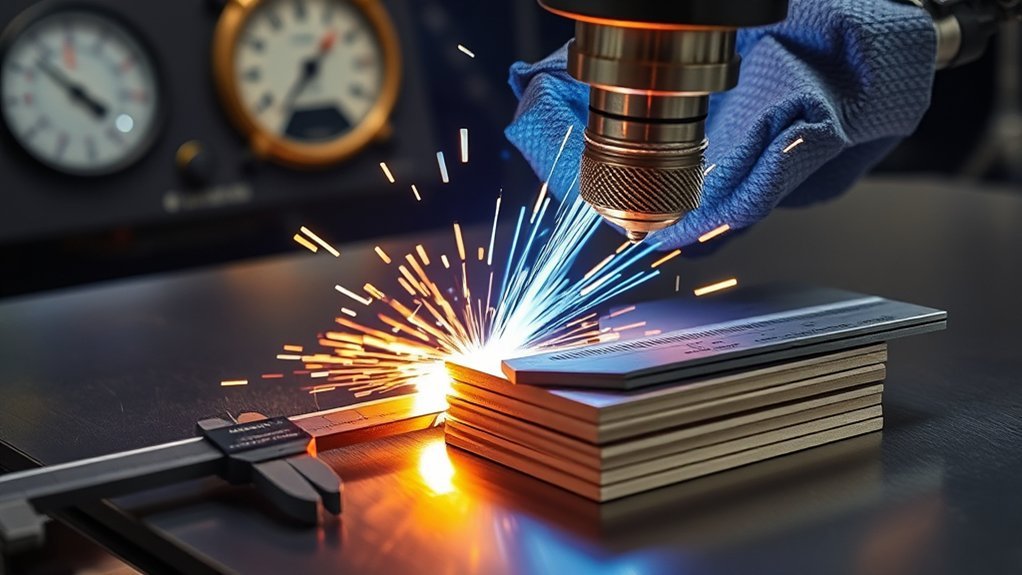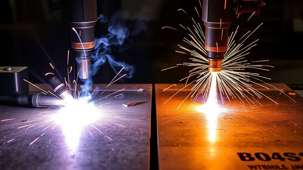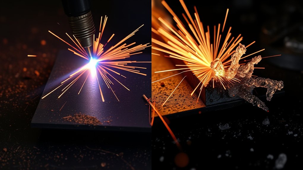
Matching plasma cutter amperage to metal thickness is not as simple as assigning one amp setting to each plate size. The correct setting depends on your exact machine, consumables, material, cutting method, air supply, travel speed, and the edge quality you need. Start with the manufacturer’s cut chart, then confirm the result on scrap before cutting the finished part.
Quick Answer
Use the cut chart for your exact plasma cutter, torch, consumable, material, and thickness. As a planning guide, current professional air-plasma systems may provide recommended capacities near 5/8 inch at 45 A, 3/4 inch at 65 A, 1 inch at 85 A, and 1-1/4 inches at 105 A.
Key Takeaways
- Amperage alone does not determine maximum thickness or cut quality.
- Use only the cut chart for the exact machine, torch, consumable, gas, and material.
- Do not confuse a recommended cut with a pierce limit or a slow sever cut.
- Edge-start material that exceeds the machine’s rated pierce capacity.
- Clean, dry air, correct torch height, proper speed, and sound consumables matter as much as current.
- Make a short test cut and inspect dross, bevel, kerf width, and spark direction before production.
At a Glance
| Time Required | 10–20 minutes for chart selection, setup, and a test cut |
| Difficulty | Moderate |
| Tools Needed | Operator manual, cut chart, thickness gauge or caliper, scrap coupon, air filtration, and required PPE |
| Cost | Usually limited to scrap material, compressed air, and normal consumable wear |
Warning: Plasma cutting exposes the operator to electric shock, ultraviolet and visible radiation, hot metal, sparks, fire, noise, and metal fumes. Identify all coatings before cutting, provide effective ventilation, keep combustibles away, and never cut a sealed or previously used container unless it has been professionally made safe.
How to Match Plasma Amperage to Thickness
- Identify the material and actual thickness. Confirm whether the workpiece is mild steel, stainless steel, aluminum, expanded metal, coated metal, or another conductive alloy. Measure it instead of relying on appearance.
- Find the exact manufacturer cut chart. Match the power supply, torch, consumable or cartridge, material, gas, amperage process, and manual or mechanized application.
- Choose the required cut level. Decide whether the job needs the best edge quality, the fastest production speed, a through-plate pierce, an edge start, or only a rough sever cut.
- Install the charted consumable. Do not use a nozzle, tip, electrode, shield, or cartridge intended for a different current or process.
- Confirm utilities and duty cycle. Check input voltage, phase, circuit capacity, air pressure, airflow, filtration, and the duty-cycle rating at the selected current.
- Make a test cut. Use scrap from the same material and thickness. Inspect the cut before committing finished stock.
Pro Tip: Record the machine, consumable, material, thickness, amperage, speed, cut height, pierce height, delay, gas pressure, and result for every successful setup. A shop-specific settings log saves more time than repeatedly guessing from a generic chart.
Products Worth Considering

Package Include: 10 Shield Cups, 50 Nozzles, 20 Swirl Baffle, and 30 Electrodes.

[Achieve Precise Cuts] PT31 Plasma Cutting Consumables – Your Essential Tool for Efficient Cutting! Whether you're working with sheet metal, steel, or any other material, superior cutting performance ensure clean, accurate, and smooth cuts.

High-Quality Material:Made of high quality material to ensure a longer lifespan and superior performance.
The Variables That Determine Real Cutting Thickness
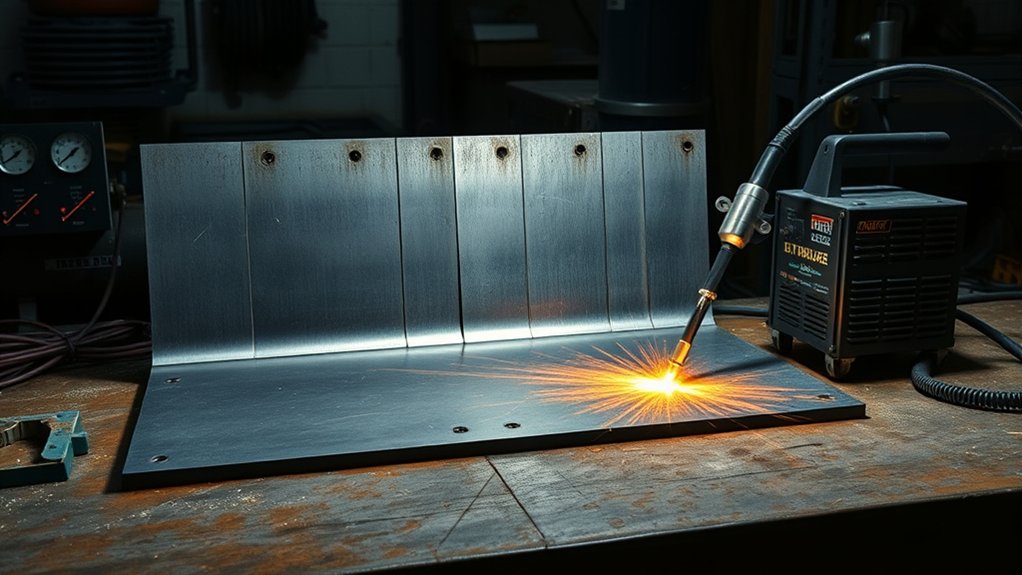
Material thickness is only one part of the setup. The following variables work together to determine whether the torch produces a clean cut, a rough sever, or no full penetration at all:
- Output amperage: Higher current can provide more cutting energy, but the torch and consumable must be designed for that current.
- Material and alloy: Mild steel, stainless steel, and aluminum respond differently to heat and process gas.
- Cut-quality target: A machine can often sever thicker material than it can cut cleanly or pierce reliably.
- Consumable process: Fine-cut, drag-cut, mechanized, unshielded, and cartridge processes have different charts.
- Travel speed: Moving too slowly widens the kerf and creates low-speed dross. Moving too quickly can leave high-speed dross or fail to penetrate.
- Cut and pierce height: Incorrect height changes bevel, kerf width, arc stability, and consumable exposure to spatter.
- Gas quality and flow: Moisture, oil, leaks, restrictions, low pressure, or inadequate compressor volume shorten consumable life and weaken the plasma jet.
- Input power and duty cycle: The available output and continuous cutting time depend on the machine’s input voltage, phase, ambient rating, and electrical supply.
- Material condition: Heavy scale, paint, plating, rust, warp, or poor work-clamp contact can affect starting and cut consistency.
For CNC cutting, torch height control, table motion, torch squareness, lead-ins, cut direction, and kerf compensation add further variables. Hypertherm’s cut-quality guidance recommends checking the process, consumables, gas, height, speed, table motion, and material together rather than changing amperage alone.
Quick Reference: Plasma Power-Class Planning
The table below uses current Hypertherm Powermax SYNC equipment as a real-world example. It is useful for planning a machine purchase, but it is not a substitute for the cut chart supplied with another model or brand.
| Power Class | Current Manufacturer Example | Rated Pierce | Hand Sever Example |
|---|---|---|---|
| 45 A | 5/8 in recommended at 20 IPM | 1/2 in | 1-1/8 in at 5 IPM |
| 65 A | 3/4 in recommended at 20 IPM; 1 in at 10 IPM | 5/8 in | 1-1/4 in at 5 IPM |
| 85 A | 1 in recommended at 20 IPM; 1-1/4 in at 10 IPM | 3/4 in | 1-1/2 in at 5 IPM |
| 105 A | 1-1/4 in recommended at 20 IPM; 1-1/2 in at 10 IPM | 7/8 in | 2 in at 5 IPM |
Note: Recommended capacity, pierce capacity, and sever capacity are different ratings. A machine may edge-start and slowly sever plate that is too thick to pierce or cut with production-quality edges.
Products Worth Considering

CNC Function: The STC850P MAX plasma cutter machine is equipped with blowback technology and Non-HF (non-high frequency) pilot arc, which are compatible with CNC systems. This setup minimizes the risk of high-frequency signal interference, thereby improving cutting stability. The non-touch blow-back pilot arc initiation ensures that the arc starts without the need for physical contact with the metal. The plasma cutter features two connection ports: a 2-pin connector for arc voltage output at 1:1 ratio and 5-pin connector for signal control. This design facilitates seamless integration with CNC cutting tables

Drag-Cut Control & Steady Tracking for HVAC and Metal Art: Smooth touch-and-go nozzle gliding directly on thick plates eliminates hand fatigue for fabricators tracing steel straightedges, cutting custom ventilation stencils, and guiding intricate metal art graphics without arc sputtering
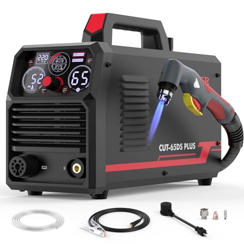
4 FUNCTIONS IN 1 MACHINE: Plate cutting, grid cutting, gouging, and marking give you more ways to handle fabrication, repair, and shop work. Plate Cutting delivers clean cuts on steel, stainless steel, and other conductive metals. Grid Cutting helps maintain a stable arc across grating and perforated metal. Gouging removes welds, rust, and damaged material. Marking creates clear guide lines for layout, hole positioning, and assembly.
Example 45 A Mild-Steel Cut Speeds
The following mechanized values illustrate why one generic speed range is not enough. They come from a 45 A air-plasma chart for one current machine and cartridge process. Another machine may require different values.
| Mild-Steel Thickness | Best-Quality Speed | Highest-Production Speed | Starting Method |
|---|---|---|---|
| 10 gauge | 95 IPM | 181 IPM | Pierce |
| 1/4 in | 46 IPM | 74 IPM | Pierce |
| 3/8 in | 33 IPM | 38 IPM | Pierce |
| 1/2 in | 18 IPM | 24 IPM | Pierce |
| 5/8 in | 13 IPM | 16 IPM | Edge start |
| 3/4 in | 7 IPM | 7 IPM | Edge start |
Use the current version of the manufacturer’s chart from its official document library. For Hypertherm SYNC systems, the relevant cut-chart guide is identified as document 810500MU.
Power Class Ranges
Choose a power class from the thickest material you cut routinely, not the thickest piece you may encounter once a year. A unit that works near its maximum rating every day will cut more slowly and place greater demands on the compressor, electrical supply, and consumables.
For sheet metal and light brackets, a 30–45 A class machine may provide enough control and capacity. General fabrication commonly falls in the 45–65 A range. Shops that routinely process plate near 3/4 inch to 1 inch may benefit from 65–85 A equipment. Thicker production work may require 105 A or a higher industrial class.
Those are purchasing ranges, not universal settings. You may use a lower-current process on a larger power supply when the cut chart calls for it.
How Gas Choice Affects the Cut
Most portable air-plasma cutters are designed primarily for clean, dry compressed air. Some systems also permit nitrogen, F5, oxygen, water shielding, or argon-hydrogen processes, but only with approved torches, gas circuits, and consumables.
- Compressed air: Economical and versatile for mild steel, stainless steel, and aluminum. It can leave an oxidized edge on stainless and aluminum.
- Oxygen: Common in industrial multi-gas systems for high-speed, low-dross mild-steel cutting. Do not use oxygen in an air-plasma machine unless the manufacturer specifically approves it.
- Nitrogen: Can improve edge appearance and reduce oxidation on stainless and aluminum. It does not automatically eliminate dross.
- F5: A mixture of 95% nitrogen and 5% hydrogen that can produce a shinier stainless edge on compatible systems, usually at a slower speed.
- Argon-hydrogen mixtures: Used on suitable industrial equipment for thick stainless or aluminum. They require systems specifically designed for the gas.
See Hypertherm’s current plasma gas selection guide before changing from the gas listed in your manual.
Quality Cut vs. Pierce and Sever Limits
A recommended cut is a thickness the manufacturer expects the machine to cut with useful speed and acceptable quality. A pierce rating is the maximum thickness that can be started through the plate under stated conditions. A sever rating is a slow maximum-thickness cut that may have heavy dross, wider kerf, more bevel, and rough edges.
Do not use the sever rating as the routine production rating. If the finished part needs square edges, close tolerances, small holes, or minimal cleanup, stay within the charted quality range.
Quality-cut settings prioritize edge finish and manageable dross, while sever settings prioritize getting through the material.
Mild Steel Amperage Guidance
Mild steel, including A36 and similar low-carbon plate, is the most predictable material for air-plasma cutting. Clean compressed air is the standard process on many portable machines. Industrial multi-gas systems may use oxygen to increase mild-steel speed and reduce dross.
The correct amperage is the charted process that gives the required edge quality at a stable speed—not simply the highest current the machine can produce.
For sheet and thin plate, lower-current or fine-cut consumables often produce a narrower kerf and better feature detail. For thicker plate, select a process that remains within the machine’s recommended capacity and duty cycle.
- Remove loose scale where the work clamp or height-sensing system needs electrical contact.
- Place the work clamp on clean metal and as close to the cutting area as practical.
- Square a machine torch to the plate in both directions.
- Use the charted cut height, pierce height, pierce delay, and speed.
- Use a lead-in long enough for the arc to stabilize before entering the finished profile.
- For CNC exterior contours, confirm the cut direction specified for the torch and consumable so the best edge stays on the part.
Stainless Steel Amperage Guidance
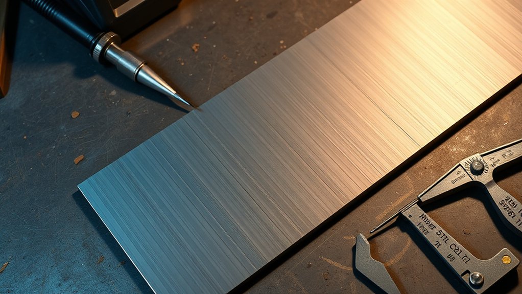
Air plasma cuts common austenitic stainless grades such as 304 and 316, but the cut edge normally develops a dark oxide layer. The amount of dross, discoloration, and bevel depends on the alloy, thickness, gas, current, consumables, height, and speed.
Air vs. Nitrogen
Air is usually the simplest and least expensive option. Nitrogen can reduce oxidation and improve edge color, but on some air-plasma processes it produces more dross. It should not be described as a universal quality upgrade.
F5 can produce a bright silver stainless edge with compatible Powermax systems. It costs more and generally requires a slower cutting speed. Multi-gas industrial systems may use other mixtures for thicker stainless.
Follow the manufacturer’s stainless-steel gas recommendations and confirm that the exact torch and consumables are approved for the gas.
Stainless Edge Quality and Dross
| Process | Typical Advantage | Important Trade-Off |
|---|---|---|
| Air | Low operating cost and broad compatibility | Dark, oxidized cut edge |
| Nitrogen | Less oxidation and improved edge color | May create more dross and costs more than air |
| F5 on approved systems | Shiny silver edge | Slower process with limited equipment compatibility |
If a stainless part will be welded, painted, passivated, or used in a corrosion-sensitive application, account for the oxide or nitride layer during post-cut preparation.
Aluminum Amperage Guidance
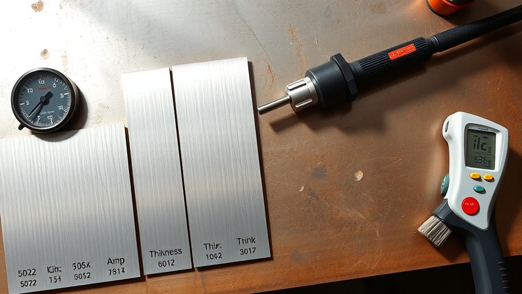
Common aluminum alloys such as 5052 and 6061 can be cut with air plasma. Aluminum transfers heat rapidly, so speed, pierce delay, and height errors can quickly enlarge the kerf or produce heavy spatter.
Compressed air is economical and works well for many portable systems. Nitrogen-based processes may improve edge appearance and reduce oxidation. Suitable industrial systems may use nitrogen with water shielding or approved argon-hydrogen mixtures for thicker aluminum.
Do not use oxygen as a general aluminum plasma gas. Hypertherm’s current aluminum cutting guidance recommends nitrogen-based or approved multi-gas processes when edge quality is the priority.
- Use the exact aluminum cut chart rather than a mild-steel chart with a speed adjustment.
- Keep pierce delay no longer than the chart requires.
- Watch for molten aluminum collecting under the cut or around slats.
- Test 5052 and 6061 separately when tight tolerances or cosmetic edges matter.
- Remove oxide and contamination as required before critical welding.
Choosing a Power Class for Your Work Mix
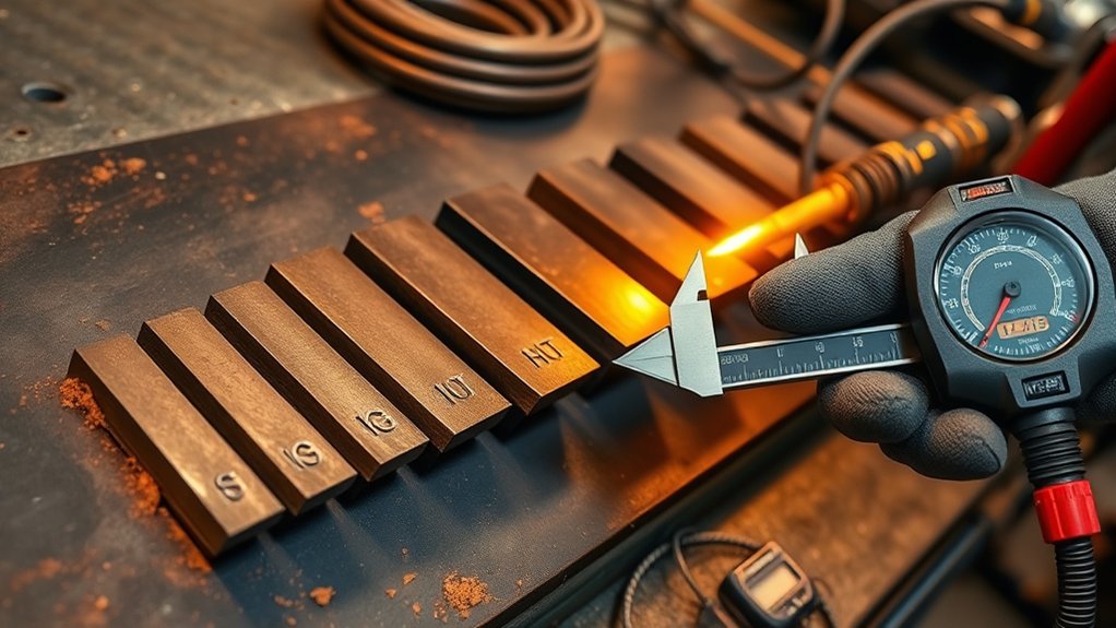
Base the purchase on the thickest material you cut routinely and the speed you need. Do not size a machine only from its advertised sever rating.
- Mostly sheet metal: Favor stable low-current operation, fine-feature consumables, and good speed control.
- Routine 1/4- to 1/2-inch fabrication: A professional 45–65 A class often provides useful capacity, depending on the model.
- Routine 1/2- to 3/4-inch plate: Compare 65–85 A systems using their recommended speed and pierce ratings.
- Routine plate near 1 inch: Compare 85–105 A equipment, compressor requirements, phase availability, and duty cycle.
- Production beyond 1 inch: Consider whether a larger air-plasma, high-definition plasma, oxyfuel, laser, or waterjet process better matches the part requirements.
Moving one power class above the minimum may provide faster production and more duty-cycle margin, but it does not mean every job should be cut at maximum current. Use the lower-current process listed for thin material when it gives better detail or kerf control.
Piercing vs. Edge-Starting
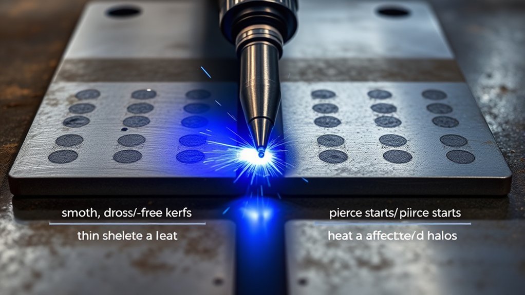
A pierce starts through the face of the plate. An edge start begins with the torch positioned so the arc can exit past the material edge. Piercing exposes the nozzle or cartridge to molten spatter, especially on thick plate.
Use a pierce when the cut chart lists a pierce height and delay for the material. This is required for internal holes and other closed features.
Use an edge start when the material exceeds the charted pierce capacity or when the cut chart specifically calls for one. Edge starting is most often associated with thicker plate, not thin sheet.
Do not assume the correct pierce height is always 1.5 or 2 times the cut height. Standard, fine-feature, and specialty processes can use very different ratios. Enter the charted pierce height, delay, cut height, and lead-in values.
Note: On a CNC table, do not begin motion before the arc has fully penetrated the plate. Moving too early can send molten metal back toward the torch and damage the consumable.
Tip Size, Kerf Width, and Air Settings
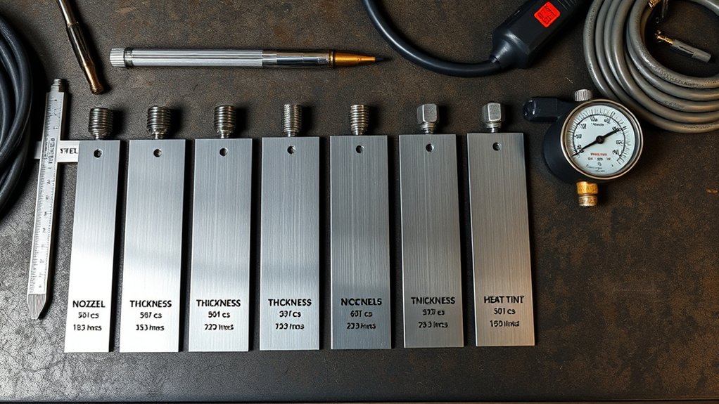
The nozzle, tip, or one-piece cartridge shapes and constricts the plasma arc. It must match the amperage and process listed in the manual. A mismatched or worn consumable can cause poor arc control, excessive bevel, low speed, wide kerf, and premature failure.
Hypertherm identifies incorrect consumable selection as a leading cause of poor cut speed and quality. Use the specified part numbers and inspect the electrode, nozzle opening, shield, O-rings, and swirl components before troubleshooting the machine.
Do not use one fixed pressure rule for every cutter. Some modern systems set operating pressure automatically. Others require a manual pressure adjustment. Measure inlet pressure while gas is flowing, because a static gauge reading can hide undersized hoses, clogged filters, regulator restrictions, or inadequate compressor volume.
For comparison, current 65 A and 85 A Powermax SYNC specifications list approximately 7.5 SCFM at 85 psi for cutting, while the current 105 A system lists approximately 9.1 SCFM at 90 psi. Other systems may require different values.
- Use clean, dry, oil-free air or the approved bottled gas.
- Drain the compressor and separator regularly.
- Use adequately sized hose, filters, dryers, and fittings.
- Check pressure during gas flow, not only while the torch is idle.
- Never substitute an unapproved combustible or oxidizing gas.
Setup Details That Improve Cut Quality
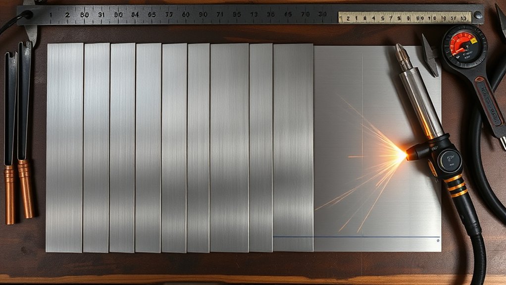
After choosing the charted amperage, verify the full setup before changing current again.
- Confirm the material and thickness.
- Install the correct consumable and operating mode.
- Inspect consumables for wear or damage.
- Check the air filter, dryer, regulator, hose, and flow capacity.
- Attach the work clamp to clean metal.
- Square the torch and level or support warped plate.
- Enter the charted speed, cut height, pierce height, delay, voltage, and kerf value.
- Cut a straight test line and a sample feature.
- Inspect the edge before making small, documented adjustments.
Plasma Cut Troubleshooting
| Symptom | Likely Checks | First Correction |
|---|---|---|
| Heavy rounded dross | Speed too slow, torch too low, excess current, hot plate | Return to charted speed and height; allow the plate to cool |
| Thin hard dross or incomplete cut | Speed too fast, current too low, low air flow, worn consumable | Verify the chart, pressure under flow, and consumable condition |
| Excessive bevel | Incorrect height, torch not square, worn nozzle, wrong cut direction | Square the torch and restore charted height |
| Wide kerf or rounded top edge | Torch too high, speed too slow, current process too large | Check height and select the lower-current charted process if available |
| Arc will not transfer | Poor work connection, paint or scale, air fault, torch lock, excessive standoff | Clean and reconnect the work clamp; check machine fault indicators |
| Short consumable life | Moisture or oil, excessive piercing, wrong height, wrong parts, low flow | Service the air system and verify every cut-chart parameter |
Change one variable at a time. If you change current, speed, height, and pressure together, you will not know which change improved or damaged the cut.
Practical Thickness Targets by Shop Type
- Automotive body and restoration: Prioritize low-current stability, narrow kerf, and heat control for thin sheet. A 30–45 A class may be appropriate, but the available low-current process matters more than the maximum rating.
- General fabrication: Shops cutting brackets, tabs, frames, and mounting plates from sheet through approximately 1/2 inch often compare 45–65 A equipment.
- Farm, maintenance, and repair: Select enough recommended capacity for the thickest routine repair, plus suitable input power and a portable compressor arrangement.
- CNC production: Consider machine interface support, torch-height control, mechanized cut charts, duty cycle, pierce capacity, consumable cost, and hole quality—not only hand-cut capacity.
- Heavy fabrication: Routine work near or above 1 inch may justify 85–105 A or larger equipment, depending on speed, edge tolerance, production volume, and available three-phase power.
Plasma Cutting Safety
Use the safety instructions supplied with the machine and follow applicable workplace rules. At minimum:
- Eye and face protection: For OSHA-covered work where the plasma arc is clearly visible, OSHA lists a minimum Shade 8 for light plasma-arc cutting below 300 A. Use properly marked safety glasses with side protection under the helmet or face protection as required.
- Clothing: Wear flame-resistant clothing, leather gloves, closed footwear, and protection from molten spray.
- Hearing: Wear hearing protection when required by the equipment instructions or a noise assessment.
- Ventilation: Use effective local exhaust. Stainless-steel plasma fumes may contain hexavalent chromium and other hazardous particles. Review the NIOSH-backed plasma-fume research.
- Coatings: Identify paint, galvanizing, plating, primers, oils, and unknown residues before heating them.
- Fire prevention: Remove combustibles, control sparks below and behind the work, keep an appropriate extinguisher nearby, and follow required fire-watch procedures.
- Containers: Never cut a tank, drum, pipe, or vessel that may contain flammable, pressurized, or toxic material unless a qualified procedure has made it safe.
- Electrical safety: Keep the machine properly grounded, inspect leads and torch parts, avoid wet conditions, and disconnect input power before internal service.
- Gas safety: Use only gases approved for the system and secure compressed-gas cylinders correctly.
Frequently Asked Questions
How do duty cycle and amperage affect continuous production cutting?
A 60% duty-cycle rating generally means the machine can cut at the stated output for six minutes in a ten-minute test period before it must cool. The rating applies at specified input power and ambient conditions. Lowering current may increase duty cycle, but the exact continuous-output point must come from the machine specifications.
What safety gear is essential when increasing amperage?
Use marked safety glasses with side protection, an appropriate shaded cutting helmet or face shield, flame-resistant clothing, leather gloves, closed footwear, and hearing protection. Provide effective ventilation and use respiratory protection when required by the material hazard assessment and applicable safety program.
How does 120 V or 240 V input affect maximum output?
Input voltage alone does not create a universal output limit. Some dual-voltage cutters reduce maximum current on 120 V, while other professional systems require 200–240 V or three-phase power. Check the data plate, circuit requirements, input-current table, and duty-cycle chart for the exact model.
Can CNC cutting speed be estimated from amperage and thickness?
Use the manufacturer’s mechanized cut chart as the starting value. Then verify actual table speed, torch height, arc voltage, kerf compensation, and consumable condition. Do not transfer a hand-cut speed or another brand’s chart directly to the CNC program.
How do altitude and humidity affect plasma cutting?
High humidity adds moisture to the compressed-air system and can shorten consumable life. Use adequate drainage, filtration, and drying. High-altitude operation can affect cooling, compressor output, and machine ratings, so consult the model’s environmental and derating instructions instead of applying a generic correction.
Can I use one plasma amperage chart for every brand?
No. Torch design, output voltage, consumable geometry, gas flow, control software, duty cycle, and manufacturer definitions vary. Use a generic chart only to compare equipment classes. Use the exact manufacturer chart to set up a cut.
Why did dross increase after I raised the amperage?
The higher-current process may require a different consumable, speed, pressure, and cut height. If only the current was increased, the torch may be moving too slowly or using the wrong nozzle. Return to a complete cut-chart process and test one adjustment at a time.
Conclusion
Match plasma amperage to thickness by following the exact cut chart, not a universal amp-to-inch formula. Select the charted consumable, gas, speed, height, and starting method; confirm input power, duty cycle, and air flow; then make a test cut. Keeping recommended, pierce, edge-start, and sever limits separate will produce faster cuts, more consistent kerfs, longer consumable life, and less grinding.
Sources
- Hypertherm Document Library — current operator manuals, mechanized-cutting guides, and cut-chart documents
- Hypertherm Powermax45 SYNC Specifications — 45 A recommended, pierce, sever, input-power, and duty-cycle ratings
- Hypertherm Powermax65 SYNC Specifications — 65 A capacity, airflow, pressure, and duty-cycle data
- Hypertherm Powermax85 SYNC Specifications — 85 A capacity, airflow, pressure, and duty-cycle data
- Hypertherm Powermax105 SYNC Specifications — 105 A capacity, airflow, pressure, and duty-cycle data
- OSHA 29 CFR 1910.133: Eye and Face Protection — minimum filter-shade guidance for plasma-arc cutting