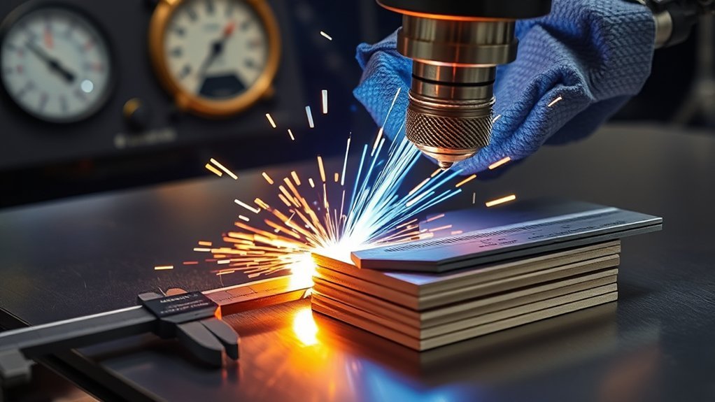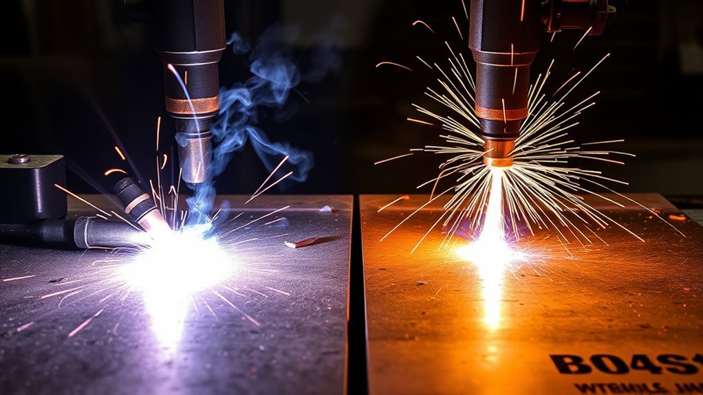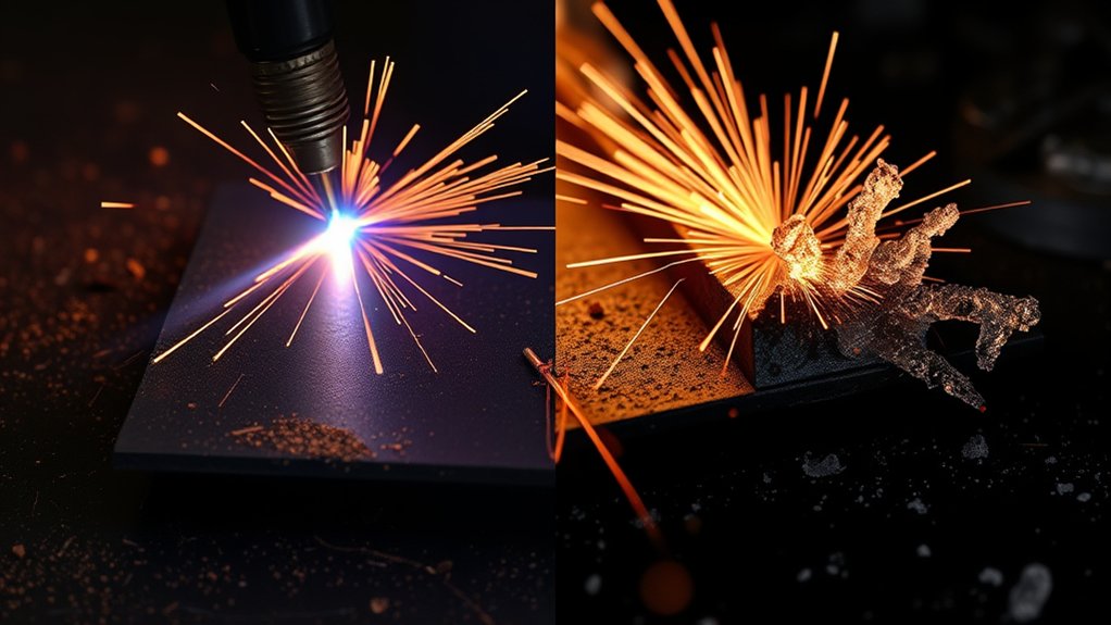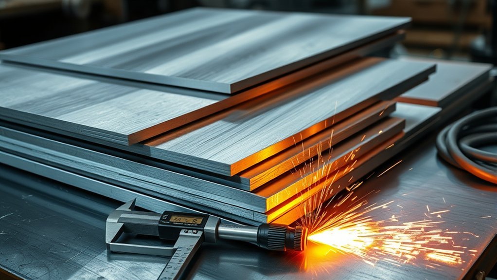
You need the right plasma cutter amps for aluminum thickness before you can tune kerf, bevel, dross, and edge quality. Start with the material thickness, choose the correct consumables, set the amperage from your machine’s cut chart, then adjust travel speed and torch height with a test coupon. For many air-plasma machines, 1/8 in aluminum starts around 25–35 A, 1/4 in around 45–60 A, 3/8 in around 60–80 A, and 1/2 in often needs 80–100+ A for cleaner work. Treat these as starting points, not universal settings.
Quick Answer
For aluminum plasma cutting, start around 25–35 A for 1/8 in, 45–60 A for 1/4 in, 60–80 A for 3/8 in, and 80–100+ A for 1/2 in. Confirm the final amperage, speed, pierce height, and gas in your plasma cutter’s manual before cutting finished parts.
Key Takeaways
- Amperage must rise with aluminum thickness, but the exact setting depends on your machine, torch, consumables, gas, and cut-quality goal.
- Too little amperage or too much speed leaves dross, bevel, and uncut spots. Too much amperage or slow travel widens the kerf and overheats the edge.
- Use dry air only when your machine calls for it. Use nitrogen or other gases only when your plasma system supports those gases.
- Run a test coupon first, measure the kerf, inspect the edge, and adjust one variable at a time.
At a Glance
| Time Required | 10–20 minutes to set up, test cut, inspect, and tune before cutting finished parts |
| Difficulty | Moderate; easy to start, but clean aluminum edges need careful tuning |
| Tools Needed | Plasma cutter, correct consumables, dry air or approved gas, ground clamp, calipers, scrap coupons, PPE, and fire extinguisher |
| Cost | Usually limited to consumable wear, gas or air drying, and scrap used for test cuts |
Warning: Plasma cutting is hot work. Wear eye and face protection with the proper shade, remove or shield combustibles, ventilate fumes, and control aluminum dust. OSHA guidance for cutting and welding includes eye protection, ventilation, fire prevention, and following manufacturer instructions for the equipment.
Why Amperage Matters When Cutting Aluminum
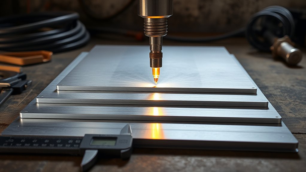
Amperage controls how much cutting energy reaches the aluminum. Set it too low, and the plasma arc may lag, leave dross, or fail to cut through. Set it too high without enough travel speed, and the kerf gets wider, the edge rounds over, and thin aluminum can warp.
The best aluminum cut is not made by amperage alone. It comes from the right balance of amps, travel speed, torch height, gas flow, clean consumables, and good grounding.
Aluminum moves heat quickly, so it can fool you. A setting that looks hot enough at the start of the cut may still leave dross if your travel speed, torch height, or air quality is off. That is why the best workflow is simple: start with the machine’s cut chart, run a test coupon, inspect the edge, then adjust one variable at a time.
For safety and setup, follow the printed or digital instructions for your exact plasma cutter. OSHA’s arc welding and cutting rules also state that manufacturer instructions for operation should be strictly followed. This matters because a 45 A handheld cutter, a 65 A shop machine, and a high-definition CNC system may all use different settings on the same aluminum thickness.
Matching Amps to Aluminum Thickness
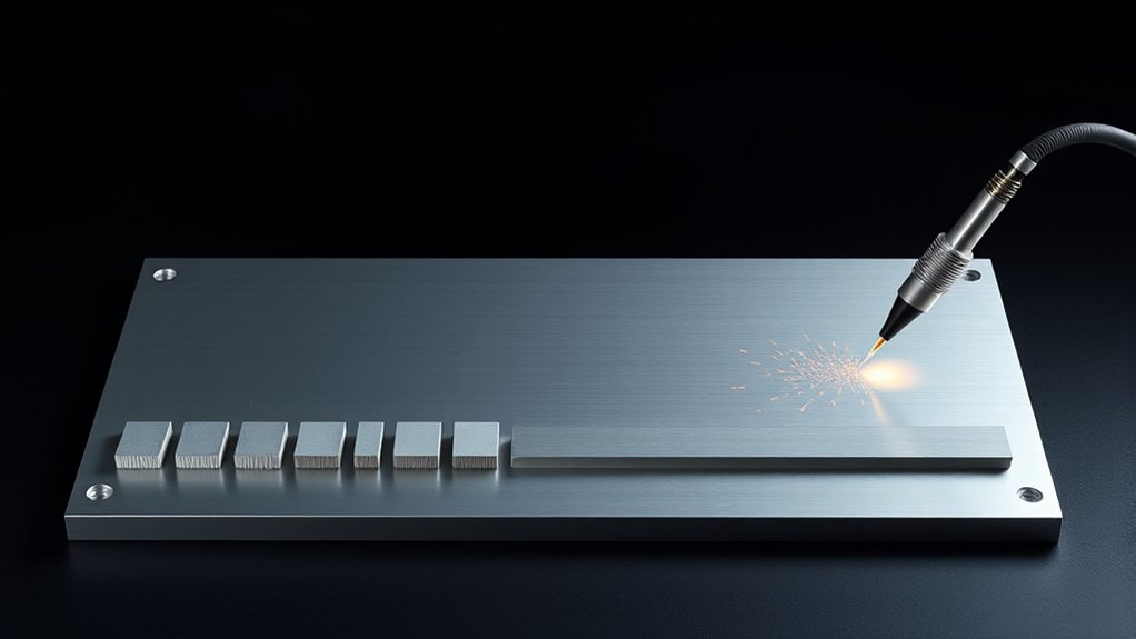
Use the table below as a starting point for common aluminum thicknesses. It is not a replacement for your machine manual. Different torches, nozzles, shield caps, air pressure, and CNC height controls can change the correct number.
| Aluminum Thickness | Starting Amps | Manual Speed Starting Point | What to Watch |
|---|---|---|---|
| 24 ga to 1/16 in | 20–30 A | Fast, steady travel | Warping, top-edge melt, and too-wide kerf |
| 1/8 in (3.2 mm) | 25–35 A, sometimes 40 A | Moderate travel | Cold dross if too slow or too low on amps |
| 1/4 in (6.4 mm) | 45–60 A | Moderate to slow travel | Bevel, heavy bottom dross, or incomplete cut |
| 3/8 in (9.5 mm) | 60–80 A | Slow, controlled travel | Arc lag and dross if the machine is undersized |
| 1/2 in (12.7 mm) | 80–100+ A for cleaner cuts | Slow travel, often better on CNC | Duty cycle, cut capacity, bevel, and bottom dross |
Thin sheet up to 1/8 in usually needs lower amperage and quick, steady motion. Mid-thickness aluminum around 1/4 in often lands in the 45–60 A range. Once you move into 3/8 in and 1/2 in aluminum, clean results usually need more amperage, a machine with enough duty cycle, and a slower travel speed.
If the kerf widens, the top edge rounds over, or the plate shows heat tint and distortion, reduce amperage or increase speed slightly. If the cut does not go through, the arc trails far behind the torch, or heavy dross sticks to the bottom, increase amperage, slow down, or check whether the machine is large enough for that thickness.
Note: A small plasma cutter may “sever” thick aluminum but still leave a rough edge. A severance rating is not the same as a clean-cut rating.
Recommended Cut Charts by Thickness Range
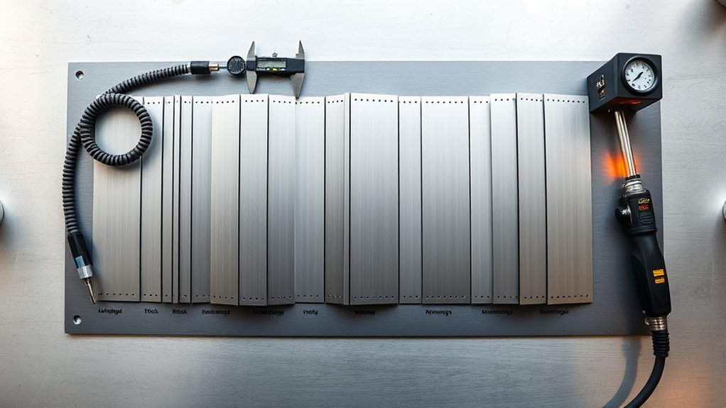
A good aluminum cut chart does more than list amperage. It should also show the consumable set, gas or air pressure, cut height, pierce height, pierce delay, and travel speed. If your plasma cutter manual gives different settings from the starting ranges here, use the manual first.
Products Worth Considering

Package Include: 10 Shield Cups, 50 Nozzles, 20 Swirl Baffle, and 30 Electrodes.

[Achieve Precise Cuts] PT31 Plasma Cutting Consumables – Your Essential Tool for Efficient Cutting! Whether you're working with sheet metal, steel, or any other material, superior cutting performance ensure clean, accurate, and smooth cuts.

High-Quality Material:Made of high quality material to ensure a longer lifespan and superior performance.
Thin-Gauge Starting Points
For thin aluminum, such as 24 ga to 1/16 in sheet, start low and move fast enough to avoid heat buildup. A range of 20–30 A is common for very thin material, but the correct setting depends on the torch and nozzle size.
Keep the torch height steady. On a drag-cap handheld setup, use the correct drag shield. On a mechanized table, set the cut height from the chart and make sure the torch height control is not diving into the sheet. Thin aluminum can warp fast, so test on scrap before cutting a finished panel.
Check the edge after the first cut. If the top edge is melted and the kerf is wide, you are too hot or too slow. If the arc skips, leaves rough uncut spots, or creates a ragged edge, you may be moving too fast or using the wrong consumables.
Mid-Thickness Performance
Mid-thickness aluminum, especially 1/8 to 1/4 in, is where many shop plasma cutters work well. Start around 25–35 A for 1/8 in and 45–60 A for 1/4 in, then tune speed from the edge quality.
Your goal is a clean cut face with light dross that chips off easily. If the bottom dross is hard and heavy, the cut may be too cold, too fast, or too far from the work. If the top edge is rounded and the kerf is oversized, the cut may be too hot or too slow.
For better accuracy, measure the kerf on a test coupon with calipers. Then use that number for kerf compensation in your CNC software or layout work. Do not assume the same kerf value will hold across different thicknesses or consumables.
Heavy Plate Parameters
For 3/8 to 1/2 in aluminum, the machine’s real cut capacity matters. A smaller plasma cutter may get through 1/2 in aluminum slowly, but it may leave a rough, beveled edge. Cleaner cuts usually need a stronger machine, the correct high-amperage consumables, and slower, steadier travel.
Start around 60–80 A for 3/8 in and 80–100+ A for 1/2 in when your plasma cutter supports those settings. Watch the duty cycle. Long cuts at high current can overheat a small power supply and cause shutdown or poor arc stability.
Use a lead-in when possible so the pierce mark stays away from the finished edge. On thick aluminum, piercing directly on the cut line can damage the edge and shorten consumable life.
Speed, Amperage, and Heat-Affected Zone
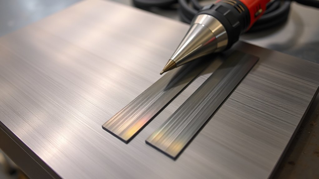
Amperage and speed work together. Amperage supplies the heat. Travel speed controls how long that heat stays in one area. The right balance gives you full penetration with a narrow kerf and a small heat-affected zone.
If you move too slowly, the aluminum edge overheats. You may see a wider kerf, rounded top edge, more warping, or soft, smeared dross. If you move too quickly, the arc trails behind, the bottom may not cut through, and the edge can show strong bevel or rough striations.
Optimal Travel Speed
Do not use one travel speed for every thickness. Thin aluminum needs faster motion. Thick aluminum needs slower motion so the arc can fully cut through. CNC systems can run much faster than hand cutting because they hold torch height and speed more consistently.
- Set the amperage and consumables from your machine’s cut chart.
- Start with the listed travel speed, or use a moderate manual speed if you are hand cutting.
- Watch the sparks under the plate. A good cut usually sends sparks through the bottom with only a slight trailing angle.
- Inspect the bottom dross and bevel after the cut cools.
- Adjust speed in small steps before changing several settings at once.
Amps-To-Thickness Pairing
Set amperage by thickness first. Then use speed to fine-tune the cut. A 1/8 in aluminum sheet does not need the same current as 1/2 in plate. A 1/2 in plate needs enough current to maintain a strong arc through the full thickness.
Use lower amperage when edge detail and narrow kerf matter more than speed. Use higher amperage when thickness and productivity matter, but only if your machine and consumables are rated for it. Running above the correct consumable rating can quickly damage the nozzle and electrode.
Minimizing HAZ Width
To reduce the heat-affected zone, do not simply lower the amperage. If you go too low, you may have to slow down so much that heat input gets worse. A better plan is to use the correct amperage for the thickness, keep the torch height steady, and move at the fastest speed that still gives a full, clean cut.
Pro Tip: Mark every test coupon with thickness, amps, speed, gas, consumables, and cut height. Those notes become your own shop cut chart.
Voltage and Torch Height for Consistent Bevel
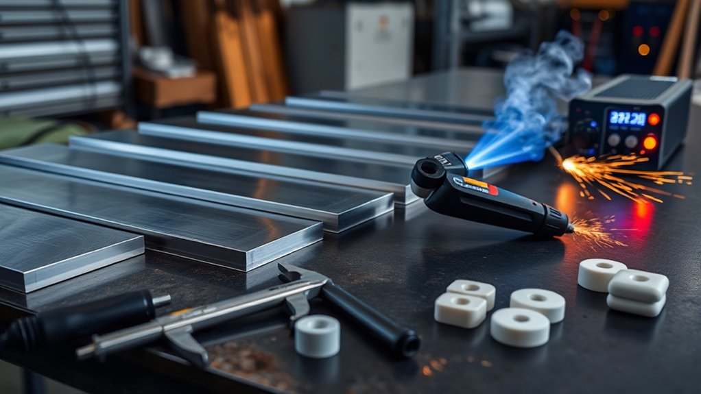
Torch height has a direct effect on bevel and kerf. If the torch is too high, the arc spreads before it reaches the aluminum. That can widen the top of the cut and create more bevel. If the torch is too low, the nozzle or shield can drag, spatter can damage consumables, and the arc can become unstable.
On a handheld plasma cutter, use the drag shield, standoff guide, or recommended hand position for your torch. On a CNC table, set the cut height from the cut chart and confirm the torch height control is reading arc voltage correctly.
Arc voltage is often used on CNC tables to maintain torch-to-work distance during the cut. Higher voltage usually means a longer arc and a higher torch. Lower voltage usually means a shorter arc and a lower torch. Because every system is different, make voltage changes in small steps and confirm the result on the cut face.
After a test cut, inspect both sides of the kerf. If one side has a different bevel than the other, check cut direction, torch squareness, worn consumables, table slats, and material warpage before blaming amperage alone.
Pierce Height and Delay to Protect Consumables
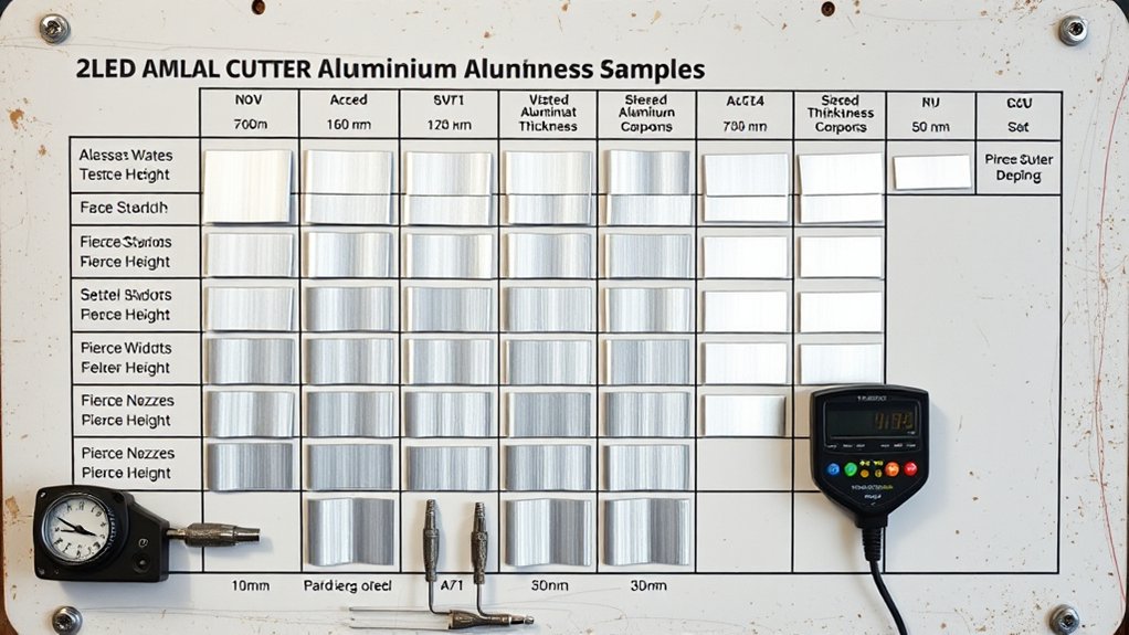
Piercing aluminum is hard on consumables because molten metal can blow back toward the torch. For this reason, the pierce height is usually higher than the cut height. Many systems use a pierce height around 1.5–2 times the cut height, but you should follow the cut chart for your exact torch.
Optimal Pierce Height
A good pierce height gives the molten aluminum room to escape without blasting the nozzle. Too low, and you may see spatter stuck to the shield, nozzle pitting, or short consumable life. Too high, and the pierce can be wide, rough, or slow to transfer into a clean cut.
On thicker aluminum, use a lead-in whenever possible. Start the pierce away from the final edge, let the arc stabilize, then move into the profile. This helps protect the finished part from a large pierce crater.
Dialing Pierce Delay
Pierce delay is the pause that lets the arc punch through before motion begins. Too short, and the machine starts moving before the pierce is complete. Too long, and the pierce crater grows wider than needed.
Use the delay listed in your cut chart as the first setting. Then inspect the pierce hole. A clean pierce should be as small as practical, fully through the material, and free from heavy upward blowback. If you change amperage, thickness, consumables, or gas, retest the delay.
Kerf Width Compensation for Accurate Parts
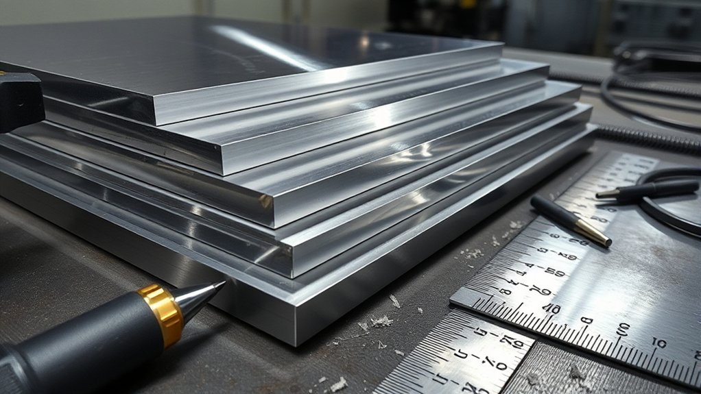
The plasma arc removes a narrow path of metal. That path is the kerf. If you do not account for kerf width, your finished aluminum part can come out undersized on outside cuts or oversized on inside holes.
- Cut a test slot: Use the same aluminum thickness, amperage, speed, consumables, and gas you plan to use on the job.
- Deburr lightly: Remove loose dross without grinding away the cut edge.
- Measure the kerf: Use calipers to measure the slot width or compare the part and drop size.
- Set compensation: Offset the toolpath by half the kerf width for inside or outside profiles.
- Validate: Cut one small test part and measure the critical features before running a full sheet.
Kerf changes when you change thickness, amperage, speed, torch height, or consumables. Worn nozzles can also widen the kerf, so do not keep using the same compensation number after the cut quality starts to drift.
Gas Selection and Flow for Clean Aluminum Cuts
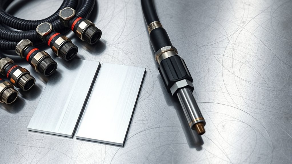
Gas choice affects arc stability, edge finish, dross, and consumable life. Many handheld plasma cutters are designed to use clean, dry compressed air. Higher-end or high-definition systems may use nitrogen or other approved gas mixes for aluminum, but only when the system manual allows it.
The most important rule is simple: do not guess gas pressure or flow. Set pressure and flow from the machine manual. Too little flow can make the arc unstable, increase dross, and damage consumables. Too much flow can also disturb the arc and hurt edge quality.
| Gas / Air Setup | Best Use | Important Note |
|---|---|---|
| Clean, dry compressed air | Most handheld and shop air-plasma machines | Use a dryer or filter. Moisture hurts cut quality and consumable life. |
| Nitrogen | Some mechanized or high-definition aluminum cutting systems | Use only if your machine and consumables are rated for it. |
| Other approved gas mixes | Specialty CNC or high-definition systems | Follow the manufacturer chart exactly. |
Check air quality before chasing amperage problems. Water, oil, or dirt in the air line can create poor starts, rough edges, and early electrode wear. Drain the compressor, service filters, and check for leaks before cutting an important part.
Sample Settings: Thin Sheet to Thick Plate
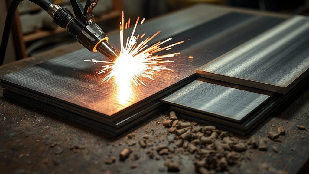
Use these sample settings to get close, then verify with your machine chart. The final numbers may change with alloy, plate condition, torch style, consumables, gas, and whether you are cutting by hand or CNC.
- 24 ga sheet: Start around 20–30 A. Move fast enough to avoid warping and top-edge melt. Keep the torch height steady.
- 1/8 in aluminum: Start around 25–35 A, or up to 40 A if your cut chart calls for it. Look for a narrow kerf and light dross.
- 1/4 in aluminum: Start around 45–60 A. Slow down enough for full penetration, but not so much that the top edge rounds over.
- 3/8 in aluminum: Start around 60–80 A if your machine supports it. Watch for arc lag and bottom dross.
- 1/2 in aluminum: Use 80–100+ A for cleaner cuts when available. Smaller machines may sever this thickness slowly, but the edge may need cleanup.
Before cutting finished parts, make one straight test cut and one shape with a corner or hole. Straight cuts show speed and dross problems. Corners and holes show whether the amperage, lead-in, kerf compensation, and height control are working together.
Products Worth Considering

Perfect Compatibility : Specifically designed for LTP5000D and LTPDC2000D plasma cutting machines, ensuring a seamless fit and optimal performance.

⚡【Precision Compatibility】 Exact fit for YESWELDER CUT 55DS Pro & 65DS (2019-2024 models). Replaces OEM# IPT40-55DS/65DS.

SET INCLUDES-2-Plasma Cutting Tips, diameter: 0. 26 mm
Troubleshooting Cut Quality and Dross
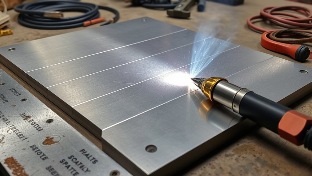
When an aluminum plasma cut looks bad, diagnose it in order. Do not change every setting at once. Start with consumables and air quality, then move to amperage, speed, height, and grounding.
| Problem | Likely Cause | Fix |
|---|---|---|
| Heavy bottom dross | Too little heat, too much speed, wrong height, or poor air flow | Check air, slow down slightly, confirm amps, and inspect consumables |
| Rounded top edge | Too much heat or too slow | Increase speed or reduce amperage within the cut-chart range |
| Strong bevel | Torch too high, worn nozzle, wrong direction, or arc lag | Set correct height, replace consumables, and verify cut direction |
| Uncut islands | Travel too fast, amperage too low, or poor work clamp connection | Slow down, raise amps if rated, and attach the clamp to clean metal |
| Excess top spatter | Pierce height too low, pierce delay wrong, or wet air | Use charted pierce settings and service the air dryer |
Also clean the aluminum before cutting. Remove heavy oxide, paint, oil, tape residue, and dirt. A stainless wire brush used only on aluminum, a clean abrasive pad, or light sanding can improve starts and reduce contamination. Wipe the surface dry before cutting.
Safety Checks Before Cutting Aluminum
Plasma cutting creates intense light, hot sparks, molten metal, fumes, noise, and fire risk. Use a welding helmet or face shield with a filter shade suitable for plasma arc cutting, safety glasses with side protection, flame-resistant clothing, leather gloves, and hearing protection. OSHA lists minimum protective shades for plasma arc cutting and requires protection from flying particles, molten metal, and injurious light radiation.
Clear the hot-work area before cutting. Where practical, move combustibles at least 35 ft away, or shield them with flame-resistant covers. Keep a fire extinguisher nearby and watch for sparks that travel under benches, behind panels, or into dust collection areas.
Use ventilation. Aluminum cutting can produce fumes, and any cutting or welding in confined spaces needs special controls. Never use oxygen for ventilation. If you are cutting painted, coated, dirty, or unknown aluminum, stop and identify the coating first because heating coatings can produce hazardous fumes.
Control aluminum dust and chips. OSHA notes that aluminum can become explosible in dust form under the right conditions. Do not let fine aluminum dust build up around sparks, grinders, or plasma cutting areas. Use proper housekeeping and dust collection methods for combustible metal dust.
Frequently Asked Questions
How does ambient temperature affect aluminum plasma cutting performance?
Ambient temperature can affect air density, moisture in the air system, and machine cooling. The bigger issue is usually air quality and duty cycle. In hot or humid conditions, drain the compressor, check filters, and watch for moisture-related rough edges or short consumable life.
What PPE is best for high-reflectivity aluminum cutting?
Use a welding helmet or face shield with the correct plasma cutting shade, safety glasses with side protection, flame-resistant clothing, leather gloves, and hearing protection. Add respiratory protection only when ventilation and exposure conditions call for it. Follow your shop safety program, OSHA rules, and the plasma cutter manual.
Can power supply duty cycle limit long continuous aluminum cuts?
Yes. Duty cycle tells you how long the plasma cutter can run at a given output before it needs cooling time. Long cuts at high amperage can trigger thermal shutdown or unstable cutting on an undersized machine. Check the duty cycle at the amperage you plan to use.
How do you manage the aluminum oxide layer without chemical cleaners?
Remove heavy oxide mechanically with a clean stainless wire brush, abrasive pad, or light sanding. Use tools dedicated to aluminum so you do not embed steel particles in the surface. Wipe the panel dry before cutting, and avoid oily rags or solvent residue near hot work.
Are there safety concerns with aluminum dust and ventilation?
Yes. Fine aluminum dust can be a combustible dust hazard, and plasma cutting fumes need ventilation. Keep the area clean, avoid dust buildup, use suitable dust-control equipment, and follow your safety program for combustible metal dust and respiratory protection.
Why does aluminum leave more dross than steel on my plasma cutter?
Aluminum conducts heat quickly and forms oxide on the surface, so it can be sensitive to speed, air quality, and torch height. Check consumables, use clean dry air, clean the surface, and tune speed before making large amperage changes.
Can you cut aluminum with regular compressed air?
Yes, many handheld plasma cutters are designed to cut aluminum with clean, dry compressed air. The key is air quality. Moisture, oil, and dirt in the air line can cause rough cuts and fast consumable wear. Use nitrogen or other gases only if your plasma system supports them.
Conclusion
Plasma cutting aluminum starts with the right amperage for the thickness, but clean results come from the full setup. Use low amperage and fast travel on thin sheet, mid-range current for 1/8–1/4 in work, and stronger machines for 3/8–1/2 in plate. Then tune speed, torch height, pierce settings, gas or air quality, and kerf compensation with a test coupon. When in doubt, follow the cut chart, change one variable at a time, and keep safety controls in place.
Sources
- OSHA 1910.133 — Eye and face protection — backs protective shade and eye/face protection guidance for plasma arc cutting.
- OSHA 1910.252 — Welding, cutting, and brazing general requirements — backs hot-work fire prevention, PPE, and ventilation guidance.
- OSHA 1910.254 — Arc welding and cutting — backs following manufacturer instructions and safe equipment operation.
- OSHA Combustible Dust: An Explosion Hazard — backs the warning that aluminum dust can be explosible in dust form.
- MillerWelds Manuals & Parts — supports using the owner’s manual for unit-specific setup, safety, troubleshooting, and maintenance details.