Any heavy-gauge cable won’t do. Undersizing causes voltage drop, heat buildup, and tripped breakers. You need to match amperage, duty cycle, and run length to the right AWG. A 30 A cutter doesn’t get treated the same as a 40 A unit over long runs. This guide gives you clear, code-aligned methods to pick the right conductor for safe, reliable plasma cutting.
Quick Answer
- Match wire gauge to your cutter’s max amperage and the distance from power source (40 A at 25 ft needs 10 AWG minimum; 60 A at 50 ft needs 6 AWG).
- Increase wire size for longer runs to keep voltage drop under 3% (add about one gauge size per 50 ft).
- Use copper for best conductivity and lower resistance. Aluminum needs a larger gauge to match copper’s performance.
- Check NEC ampacity tables and apply temperature derating factors before final selection.
- Always run a dedicated ground conductor at the same gauge as your power feed.
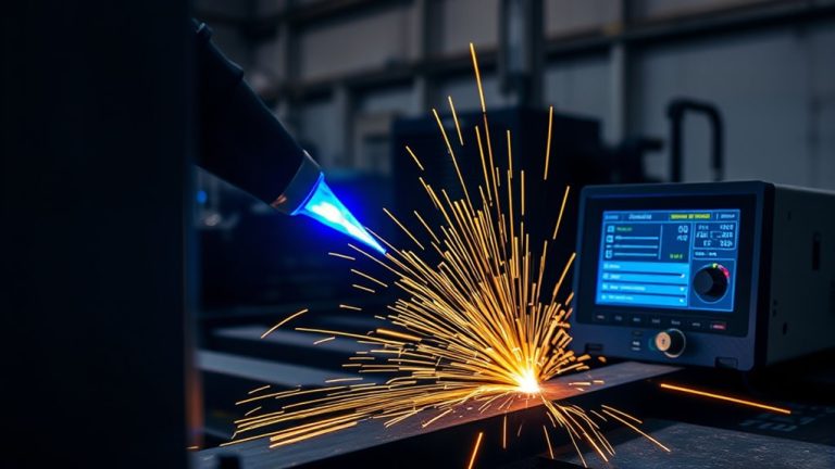
How Plasma Cutter Amps and Duty Cycle Affect Wire Size
Plasma cutters draw substantial current. Match your wire size to the cutter’s amperage and duty cycle to avoid overheating and voltage drop.
Start with amperage. Higher amperage requires thicker conductors to safely carry continuous current without excessive heat. A 40 A cutter typically needs at least 8 AWG for short runs to prevent overheating and maintain performance.
Factor in duty cycle next. Longer duty cycles mean the cutter runs longer before cooling. This increases sustained heating in both the torch and supply wiring. You may need a heavier gauge to handle that sustained load.
For longer runs (beyond about 50 feet), increase gauge further to counter voltage drop.
Consult ampacity charts and manufacturer guidance to select the proper conductor. This ensures compliance with electrical standards and reliable cutter operation.
Products Worth Considering

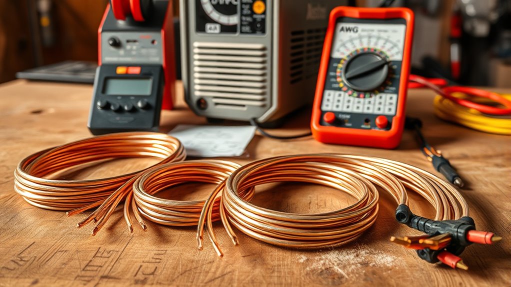
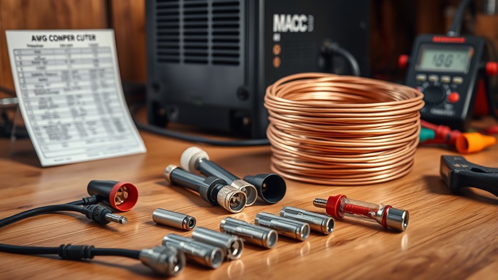
【8.29 mm² Tinned copper core】8 AWG Gauge Silicone Wire consists of 1650 strands of 0.08mm copper wire, conductor diameter: 3.0mm, outer diameter: 6.0mm, insulating silicone thickness: 1.34mm, conductor resistance: 4.0 Ω/km, current 66A.

【Material 】Cable cutters are manufactured from 65# manganese steel with precision dual ground cutting blades.

Stripping Capability: The wire stripper can be used to cut and stripper/crimp 6-12 AWG (6/8/10/12) stranded wire. Cleanly shears 8-32 and 10-32 screws, with holes for looping and bending wire
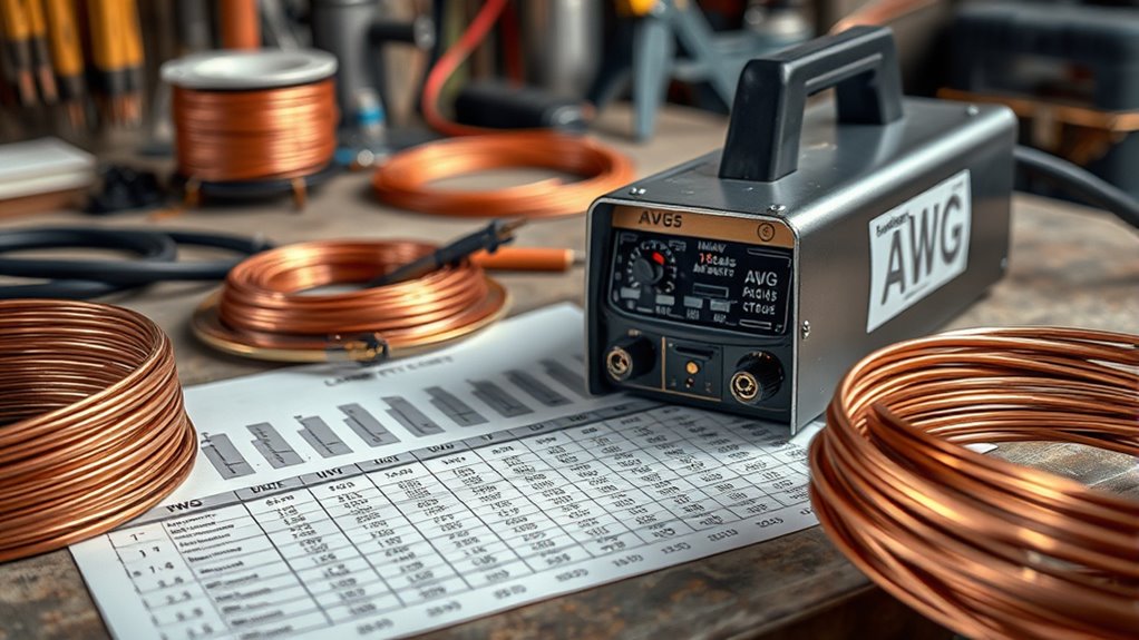
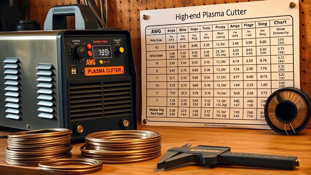
AWG Chart: Recommended Wire Sizes by Current and Run Length
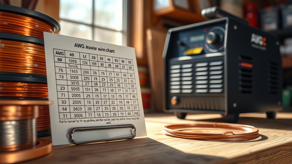
This AWG chart helps you match cutter amperage to the proper conductor size.
Increasing run length forces you to use a heavier gauge to limit voltage drop. For example, 30 A needs 10 AWG up to about 25 ft but 8 AWG at 50 ft.
Also factor in NEC’s 3% voltage-drop guidance plus insulation and temperature effects when finalizing wire selection.
Products Worth Considering

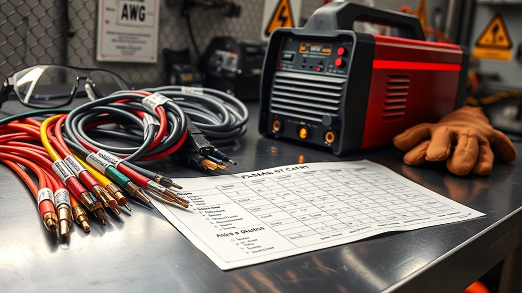
FORGED STEEL BLADES: Precision ground edges for clean cuts through copper and aluminum cables.
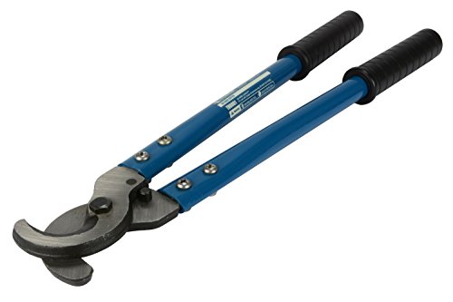
Effortlessly cuts Copper & Aluminum electrical wire up to 4/0 gauge

Dual Measurement System: Features both American Wire Gauge (AWG) sizes 0-36 and SAE sizes from 0.005" to 0.325", eliminating the need for separate gauges
Amps vs. Gauge
Choosing the right wire gauge comes down to matching your cutter’s amperage and run length. This minimizes voltage drop and meets NEC ampacity requirements.
Balance amps and resistance. Higher current increases heating and voltage loss. Select a gauge that keeps resistance low and stays within NEC ampacity tables.
- For 40 amps and short runs (≤25 ft) use 10 AWG minimum. It limits resistance and preserves cutter performance.
- For 60 amps up to 50 ft choose 6 AWG to reduce voltage-drop risk and meet ampacity expectations.
- Verify conductor ampacity vs. device rating and local code. If in doubt, upsize gauge to guarantee safe, reliable operation.
Length and Voltage Drop
Long runs require progressively larger AWG to keep voltage drop under the commonly accepted 3% limit. Use an ampacity/voltage-drop chart to match current and run length. This ensures the cutter gets adequate voltage and the conductor doesn’t overheat.
Size conductors so voltage drop and distance don’t compromise cutting performance or electrical safety. A 20 A cutter at 50 ft calls for at least 10 AWG. A 30 A cutter at 100 ft should use 8 AWG.
Consult the ampacity chart for other combinations of current and run length. Adjust for ambient temperature or conduit fill.
Always verify that chosen wire meets both ampacity and maximum voltage-drop criteria before installation.
Voltage Drop and Why Distance Changes Your Gauge Choice
Wire resistance eats voltage over distance. Performance drops if you don’t size conductors to limit voltage loss to about 3% for a plasma cutter.
Base voltage calculations on load amperage and run length. Wire resistance per foot multiplies with current to produce drop. NEC guidance tells you to evaluate ampacity and length together, not ampacity alone.
- Calculate: Determine cutter amps and round-trip feet. Use wire resistance to compute volts lost. Keep loss ≤3% of supply voltage.
- Select gauge: Longer runs require lower AWG (thicker wire) to reduce resistance. A 30 A cutter at 50 ft often needs 10 AWG versus 12 AWG for short runs.
- Verify: Confirm selected wire meets ampacity, temperature rating, and NEC voltage-drop recommendations to prevent underperformance or nuisance faults.
Follow precise voltage calculations and resistance data tables when choosing conductor size. Don’t rely on amp rating alone.
Copper Vs Aluminum: Material Considerations for Plasma Cutter Leads
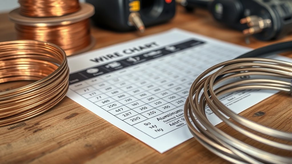
Favor copper for plasma leads when conductivity and low resistance are priorities. It carries current more efficiently than aluminum.
If weight and flexibility matter (for example on portable rigs), aluminum can be attractive. But you’ll need a larger gauge to match copper’s ampacity.
Always match material choice to the installation. Balance required gauge, heat risk, and handling needs.
Conductivity and Resistance
Both copper and aluminum will carry current to a plasma cutter. But copper’s superior conductivity and lower resistance make it the better choice for high-current leads.
Copper offers roughly 100% base conductivity versus about 61% for aluminum. This means lower resistance, reduced voltage drop, and less heating under load.
- Conductivity: Copper’s low resistivity (~0.0000017 Ω/m) yields more efficient current transmission than aluminum (~0.0000028 Ω/m).
- Ampacity: You can use 10 AWG copper at 30 A. Aluminum requires a larger gauge (typically 8 AWG) to match performance.
- Durability: Copper resists corrosion and physical damage better. It maintains conductive integrity in demanding fabrication environments.
Weight and Flexibility
Pay attention to weight and flexibility when handling leads for a plasma cutter. They directly affect portability and ease of routing.
Copper is heavier but more conductive and generally stiffer. Aluminum is lighter and easier to maneuver but needs a larger diameter to match copper’s ampacity.
Copper’s higher density increases pack weight but reduces required cross-section for given amps. This improves heat management and current transfer.
Aluminum gives flexibility benefits in handheld setups and reduces transport strain. But its lower tensile strength and larger required diameter can complicate routing and attachment hardware.
Choose copper where ampacity, heat control, and mechanical durability matter. Choose aluminum only when low weight and cost override those standards.
Grounding, Connectors, and Practical Installation Tips
A solid electrical system starts with proper grounding. Run a dedicated ground conductor at least the same gauge as your power feed. Bond it to the cutter chassis and local earth, complying with NEC requirements. This reduces shock risk.
Use connectors with proper ratings. Connector ratings must meet or exceed the cutter’s continuous and peak amperage to prevent overheating.
- Choose connectors rated ≥ the machine’s amps (many use 40 A minimum). Use crimp or screw types rated for heat. Inspect for corrosion.
- Keep feed length short to limit voltage drop. Match gauge to ampacity and run the ground parallel to the hot conductors, using proper strain relief.
- Follow NEC wiring methods. Secure enclosures. Torque terminals to manufacturer specs. Document installations for future service.
Maintain high-quality terminations and periodic checks. Poor connectors increase resistance, heat, and failure risk.
Calculating Wire Size Step-by-Step for Your Setup
Now that your grounding and connectors are sorted, calculate the wire size by starting with the cutter’s maximum amperage rating from the manufacturer.
Use this step-by-step method:
Note the rated amps. Measure one-way distance to the power source. Consult an ampacity chart for AWG versus amperage and distance. Adjust for wire insulation and ambient temperature.
If temperature or insulation reduces ampacity, pick the next larger AWG. Confirm compliance with local electrical codes.
| Step | Action | Example |
|---|---|---|
| 1 | Record cutter max amps | 40 A |
| 2 | Measure distance | 50 ft |
| 3 | Check ampacity chart | 6 AWG recommended |
| 4 | Adjust for insulation/temp | Use larger gauge if needed |
| 5 | Verify code compliance | Local rules met |
Apply conservative margins for voltage drop and heat. Document your choices and keep manufacturer data and code references with the installation records.
Common Mistakes and Safety Rules When Sizing Plasma Cutter Cables
Ignoring proper cable sizing risks overheating, excessive voltage drop, and code violations. These mistakes can cause equipment failure or fire.
Avoid common mistakes and follow safety guidelines. Never undersize wire for the cutter’s amp draw (a 50 A unit needs 6 AWG). Don’t ignore run length. Increase wire size about 10% per 50 ft to limit voltage drop.
Never undersize conductors. Match cutter amps (50 A ≈ 6 AWG) and upsize about 10% per 50 ft for voltage drop.
- Check ampacity and NEC: Follow manufacturer specs and NEC ampacity tables. Select conductor and insulation rated for the environment (90°C where required). Document calculations.
- Inspect and maintain: Routinely examine cables for frays, damaged insulation, or overheating discoloration. Replace compromised cables immediately to prevent shock or failure.
- Install correctly: Use proper terminations. Secure routing to avoid mechanical damage. Ground per code.
Adhere to these safety guidelines to minimize risk, maintain performance, and stay code-compliant.
Frequently Asked Questions
Can I Use Extension Cords Safely With a Plasma Cutter?
You can, but only with properly sized, heavy-duty extension cords matched to cutter amperage and length. Use grounded, welded-plug cords. Minimize voltage drop. Avoid coils. Inspect regularly and follow safe usage standards and manufacturer recommendations.
How Does Ambient Temperature Affect Wire Ampacity for Cutters?
Ambient temperature reduces wire ampacity. You’ll de-rate capacity as heat rises because wire conductivity worsens and heat dissipation shrinks. Follow standards. Apply specified correction factors. Choose larger AWG or improved cooling accordingly.
Are Inverter Plasma Cutters Different for Wire Sizing?
Yes, but verify specifics. Inverter plasma cutters often raise efficiency and alter power requirements. Size wire to the actual input current, duty cycle, and local code for safe, standards-focused installation.
What Wire Insulation Type Is Best for Plasma Cutter Leads?
Use high-temperature, oil-resistant EPDM or silicone rubber wire insulation for plasma cutter leads. They give superior heat, arc, and chemical resistance while maintaining lead flexibility. They meet welding equipment standards and ensure durable, safe performance.
Can Battery-Powered Plasma Cutters Use the Same Gauge Wires?
Yes, you can often use the same gauge. But match wire gauge to battery capacity and current draw. Guarantee sufficient ampacity and low voltage drop. Prioritize wire flexibility for portable leads to meet safety and performance standards.
Conclusion
Amps, duty cycle, and distance dictate cable choice. Pick the largest gauge that meets both ampacity and voltage-drop limits.
Treat copper as the default. Upsize for long runs. Follow NEC ampacity tables, proper grounding, and quality connectors.
Measure run length. Calculate voltage drop. Choose a wire that keeps cutter performance and safety within spec. Don’t gamble when lives and equipment depend on correct wiring.