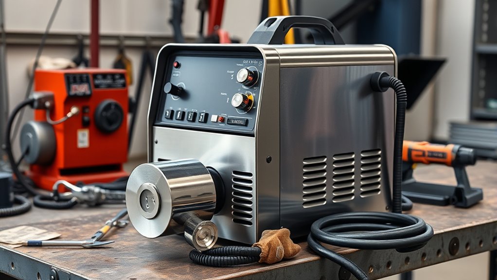
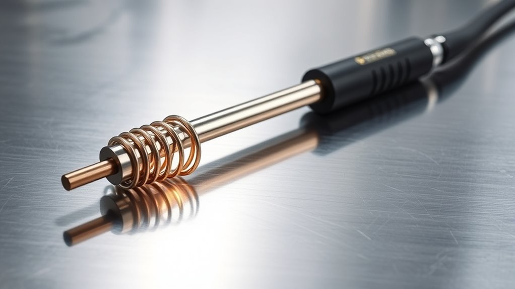
Your choice of plasma cutter torch affects control, cut speed, edge quality, consumable life, and whether the system can work with a CNC table. The key is not simply “drag for thin metal and standoff for thick metal.” You must match the torch, approved consumables, cut height, output current, air supply, and cutting method to the exact plasma system.
Quick Answer
Choose a handheld torch for portable or freehand work and a machine torch for fixed CNC mounting. Use drag cutting only with manufacturer-approved drag consumables. Use the cut-chart standoff for exposed or mechanized nozzles. Never select a torch by a universal amperage, voltage, or height rule.
Key Takeaways
- Handheld and machine torches can share a power supply, but their handles, mounting bodies, trigger controls, and CNC connections differ.
- Drag cutting is not universally limited to 40 amps. Some systems provide approved drag shields or cartridges at higher output.
- Standoff is not always 3–4 mm. Use the torch-to-work distance in the manufacturer’s cut chart.
- Input voltage does not determine cutting thickness by itself. Compare rated capacity, output amperage, cut speed, duty cycle, and branch-circuit requirements.
- Clean, dry air and correctly matched consumables are essential for stable cuts and normal torch life.
At a Glance
| Time Required | About 10–20 minutes to review the cut chart, torch options, consumables, air requirements, and CNC connections |
| Difficulty | Beginner for handheld selection; intermediate for CNC integration |
| Tools Needed | Current operator manual, cut chart, consumable chart, air-pressure gauge, and sample material for a test cut |
| Cost | No cost to compare specifications; replacement torches, CNC interfaces, height controls, guides, and consumables vary by system |
Warning: Plasma cutting creates intense arc radiation, sparks, molten metal, fumes, noise, and electrical hazards. Wear the PPE required by the operator manual, provide effective ventilation, remove combustibles, and never cut a closed container or a vessel that may have held fuel, solvent, or pressurized material. Disconnect input power before servicing the torch or changing consumables.
Types of Plasma Cutter Torches and How They Work
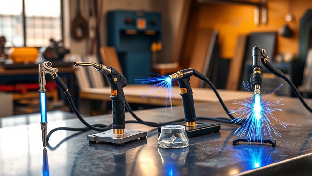
Plasma cutter torches are commonly sold as handheld, machine-mounted, or robotic designs. All create a constricted plasma arc, but their bodies, controls, lead connections, cooling needs, and mounting arrangements are built for different jobs.
Products Worth Considering

PT31 Plasma Torch: standard length: 16ft; air pressure: 4.5-5.5bar; duty cycle for 60% with 30A

S45 Plasma Torch Body Head

60amps output current, suitable for Bestarc BTC500XP BTC650XP cutting machine
What Is Inside a Plasma Torch?
Traditional plasma torches use several consumable parts. Names vary by manufacturer, but the stack commonly includes:
- Electrode: Carries current and contains an emissive insert, often hafnium in air-plasma systems.
- Nozzle or tip: Constricts and directs the plasma jet. A worn or oval opening produces a wider, less stable arc.
- Swirl ring: Controls gas movement around the electrode and helps stabilize the plasma column.
- Retaining cap: Holds the consumable stack in the torch.
- Shield, drag shield, or deflector: Protects the nozzle and may establish the required physical spacing from the plate.
Newer systems may combine several of these parts into a one-piece cartridge. Whether the parts are separate or combined, use only the part numbers approved for the torch, output current, and process.
Handheld Plasma Torches
A handheld torch has a grip and trigger designed for manual control. It is the practical choice for repair work, demolition, field fabrication, templates, artwork, and small batches.
Handheld torches may use a drag shield, a bare nozzle held off the plate, a roller guide, or other approved accessories. The operator controls torch angle, travel speed, and path, so cut quality depends heavily on a steady motion and correct setup.
Machine-Mounted Plasma Torches
A machine torch usually has a straight cylindrical body that can be clamped squarely in a CNC gantry, pipe cutter, track burner, or robotic mount. Instead of a hand trigger, the CNC starts and stops the arc through an approved machine interface.
For accurate work, the system normally uses initial-height sensing, a specified pierce height, and torch-height control. The height controller monitors arc voltage and adjusts the torch as the plate rises, falls, or warps. Hypertherm explains that correct torch-to-work distance affects both cut quality and consumable life, so the value should come from the system’s cut chart rather than a general rule.
Arc-Starting Systems
Starting terms are often mixed together. A pilot arc is the preliminary arc inside or just outside the torch before the main cutting arc transfers to the workpiece. The hardware may initiate that pilot arc through high frequency, contact starting, or a blowback-style mechanism.
- High-frequency start: Uses high-voltage, high-frequency energy. It can create electrical noise that disrupts nearby CNC controls, computers, and communications equipment.
- Contact or blowback start: Uses controlled movement between internal torch components to initiate the pilot arc with much less electrical interference.
- Auto-restart or expanded-metal mode: Re-establishes the cutting arc as the torch crosses gaps, mesh, or perforated material.
For CNC use, favor a manufacturer-approved machine interface and a starting design intended for electronic controls. Miller’s handheld plasma-cutter guide explains the practical difference between high-frequency and contact-start systems.
Drag Tips vs. Standoff Tips: Key Differences
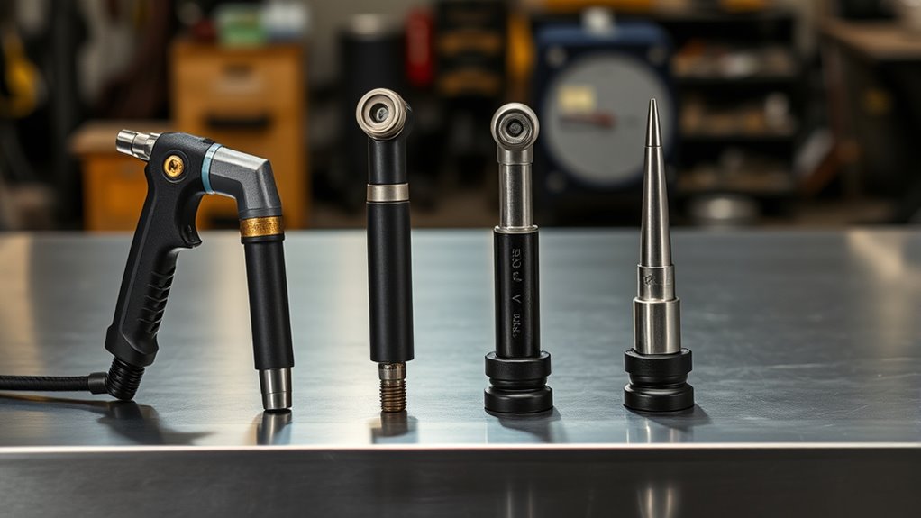
The terms drag tip, drag shield, and standoff tip are not used identically by every manufacturer. The most useful distinction is whether the approved consumable assembly can touch the work or whether the exposed nozzle must remain a set distance above it.
| Feature | Approved Drag Setup | Standoff Setup |
|---|---|---|
| Contact with plate | Shield or cartridge may ride on the work | Nozzle or shield stays at the cut-chart height |
| Best use | Freehand lines, templates, repair work, and portable cutting | CNC cutting, exposed extended tips, bevel work, and applications requiring controlled height |
| Height control | Physical shield design helps maintain spacing | Operator, guide, or automatic THC maintains spacing |
| Main risk | Using an unapproved contact technique or dragging debris into the shield | Incorrect height causing bevel, top rounding, misfires, or nozzle damage |
| Amperage | Limited to the rating of the approved drag consumable—not a universal 40 A maximum | Limited to the rating of the nozzle, electrode, torch, and power supply |
The correct cut height is the value in the manufacturer’s cut chart—not a universal 3–4 mm rule.
Drag cutting can make a handheld torch easier to control because the operator can rest the approved shield on the plate or a straightedge. Hypertherm describes drag tips as useful for controlled cutting on thin metal, but the permitted current and thickness still depend on the exact system.
A standoff arrangement protects an exposed nozzle from direct plate contact. Correct height keeps the arc focused. Excessive height can cause a wide kerf, top-edge rounding, positive bevel, and failure to transfer the arc. Too little height can cause negative bevel, double arcing, or damage during piercing.
Pro Tip: Do not assume the part called a “tip” is meant to touch the metal. Check the consumable diagram. On some torches, the drag shield touches the work while the nozzle remains protected behind it.
Standoff tips can deliver excellent speed and thickness capacity, but only when the cut height, speed, gas flow, and consumables match the power supply. The internal article provides additional 60-amp context; use the manufacturer’s cut chart as the controlling specification.
Choosing the Right Torch for Your Application
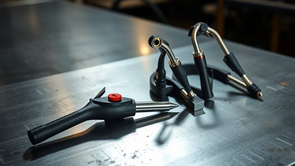
The right torch directly affects productivity and cut quality, but torch style is only one part of the decision. Work through the following factors before buying a replacement torch, consumable set, or CNC package.
Products Worth Considering
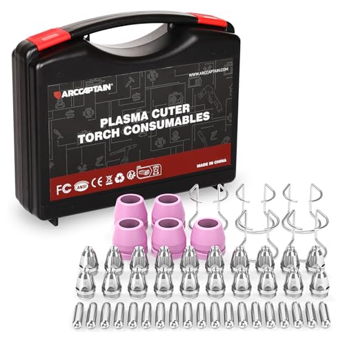
Package Include: 5 Shield Cups, 20 Nozzles .040", 5 Wire Spacer Guides, and 20 Electrodes.

Package Include: 5 Shield Cups, 20 Nozzles .045", 5 Wire Spacer Guides, and 20 Electrodes.

Fit for: SG-55 AG-60 plasma cutter torch head.
1. Start With Rated Cutting Capacity
Determine the material and thickness you cut most often. Compare the machine’s rated cut at a stated speed rather than relying on its maximum severance claim.
- Rated or recommended cut: The thickness the machine can cut at a useful speed and quality.
- Severance cut: The thickest material it may separate slowly, usually with more bevel and cleanup.
- Pierce capacity: The thickness through which the torch can safely start in the middle of the plate.
Piercing is harder on consumables than an edge start because molten metal is directed back toward the torch. When the material exceeds the approved pierce capacity, start at an edge or use another process.
2. Separate Input Voltage From Output Current
A 120- or 240-volt label describes the electricity supplied to the power source. Torch output is measured in amps. A dual-voltage cutter may deliver less output on a small 120-volt branch circuit, but some models can reach their rated output on a properly sized 120-volt circuit.
Do not use “120 volts equals 3/8 inch” as a selection rule. Confirm:
- Rated output amperage at each supported input voltage.
- Required breaker and conductor size.
- Rated cut thickness and speed for the material.
- Duty cycle at the intended output and ambient temperature.
3. Match Every Consumable to the Torch
The shield, nozzle, electrode, swirl ring, retaining cap, and cartridge must belong to a compatible set. Mixing parts that merely fit can alter gas flow, spacing, cooling, and arc constriction.
Verify the consumable part numbers for:
- Torch model and lead length.
- Handheld or mechanized operation.
- Output amperage.
- Cutting, gouging, marking, or fine-cutting mode.
- Material and process gas where applicable.
4. Check Airflow, Not Just Tank Pressure
Portable air-plasma systems require clean, dry, oil-free air at a specified pressure and flow rate. A compressor can show adequate static pressure but fall below the required pressure while the torch is flowing.
Read the manual for the required standard cubic feet per minute and inlet pressure. Include pressure losses through long hoses, small quick-connects, filters, dryers, and regulators. Moisture or oil can reduce cut quality and consumable life.
5. Choose for the Workflow
| Application | Practical Torch Choice | Priority |
|---|---|---|
| Field repair and demolition | Handheld torch with rugged, approved drag or standoff consumables | Portability, lead length, trigger safety, and easy consumable changes |
| Templates and metal artwork | Handheld torch with drag shield, straightedge, circle guide, or roller guide | Visibility, steady spacing, narrow kerf, and low-current consumables |
| Repeat production parts | Machine torch with CNC interface and automatic THC | Repeatability, cut charts, pierce control, and duty cycle |
| Pipe, tube, or robotic cutting | Machine or robotic torch approved for the mount and motion system | Torch dimensions, collision protection, lead routing, and interface compatibility |
| Thick industrial plate | Industrial mechanized torch and matched power supply | Rated process, gas console, cooling, pierce capacity, and production duty cycle |
Using a Handheld Torch on a CNC Table
A handheld torch can sometimes be mounted on a light-duty CNC table, but a mechanical clamp alone does not make it CNC-ready. Confirm that the plasma manufacturer supports mechanized operation with that power supply and torch.
A complete CNC installation may require:
- A rigid mount that holds the torch square without crushing its body.
- An approved remote-start or machine-interface connection.
- A divided arc-voltage output for the torch-height controller.
- Initial-height sensing and a method for detecting the plate.
- Correct pierce delay, pierce height, transfer height, and cut height.
- Electrical grounding, cable separation, and noise control suitable for the starting system.
- Safe torch-lead routing that prevents snagging or repeated sharp bending.
A straight machine torch is usually easier to align and service. It also avoids fastening a hand trigger in the on position or building an improvised trigger actuator.
Note: Torch-height control does more than hold one fixed gap. It normally uses initial-height sensing for the pierce and arc voltage to maintain the programmed cut height while the plate moves or warps.
Maintenance, Consumables, and Best Practices
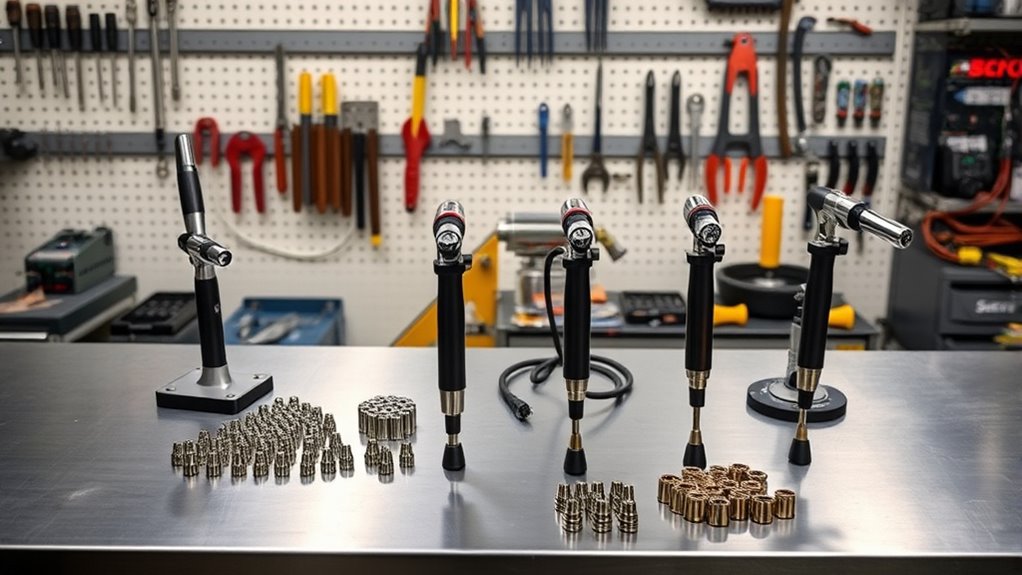
Choosing the right torch gets you part of the way there. Maintaining the air system and consumables keeps the arc centered and the cuts repeatable.
Inspect Consumables Safely
Turn off and isolate input power before removing the retaining cap, cartridge, electrode, or nozzle. Do not rely only on a cap sensor or torch-disable switch when performing maintenance.
Look for:
- A nozzle opening that is enlarged, nicked, burned, or oval.
- An electrode pit that has reached the replacement limit in the current manual.
- Blocked shield or swirl-ring gas holes.
- Cracks, burns, missing material, or signs of double arcing.
- Damaged O-rings or excess lubricant that could block gas passages.
- Loose, mismatched, or incorrectly installed components.
Some older manuals specify an electrode pit near 1/16 inch, but that value is not universal. Modern cartridges and other torch families may use different wear criteria or electronic life tracking.
Maintain Clean, Dry Air
Drain the compressor tank, inspect filters, and replace saturated elements. Check inlet pressure while gas is flowing. The required pressure and volume can differ substantially between small portable systems and larger torches, so use the specification in the current operator manual.
Respect the Duty Cycle
Duty cycle is the percentage of a test period—commonly ten minutes—that the machine can cut at a stated output and ambient temperature before cooling is required. A 60% rating under the stated test conditions means six minutes of arc-on time followed by four minutes of cooling.
Do not block cooling vents or repeatedly reset a machine that has reached thermal protection. If production regularly exceeds the duty cycle, use a higher-capacity system.
Remove Dross After the Part Cools
Allow the work to cool and secure it before using a scraper, chipping tool, file, or grinder. Wear eye and hearing protection and direct chips away from people. Dross removal cleans the finished part; it does not extend the life of consumables already used for the cut.
Troubleshooting Poor Plasma Cuts
Do not replace the torch until you rule out setup problems. Hypertherm’s plasma cut-quality guidance identifies speed, cut height, gas delivery, consumables, torch alignment, and machine motion as common causes.
| Symptom | Likely Checks | Correction |
|---|---|---|
| Heavy, bubbly bottom dross | Travel may be too slow; plate may be hot; gas or consumables may be poor | Increase speed within the cut chart and inspect gas delivery and consumables |
| Narrow, hard bottom dross with lagging arc lines | Travel may be too fast | Reduce speed to the recommended range |
| Positive bevel or rounded top edge | Torch may be too high, tilted, or using worn consumables | Lower to the charted height, square the torch, and inspect the nozzle |
| Negative bevel or undercut at the bottom | Torch may be too low | Increase torch-to-work distance to the specified height |
| Arc sputters or goes out | Low flowing pressure, moisture, restriction, poor work connection, or worn parts | Check pressure under flow, filters, hoses, work clamp, and consumables |
| Nozzle fails early during piercing | Pierce height too low, delay too short, or material beyond pierce rating | Use the charted pierce height and delay or start from the plate edge |
Plasma Cutting Safety
Use safety glasses beneath a properly rated welding helmet or face shield, flame-resistant clothing, suitable gloves, closed footwear, and hearing protection. Select the filter shade from the operator manual and applicable workplace rules rather than assuming one shade suits every output.
Provide local exhaust ventilation where needed. Cutting galvanized, painted, plated, stainless, or unknown metal can release hazardous fumes. Remove coatings only with a safe method and identify the base material before cutting.
OSHA’s welding and cutting requirements call for adequate ventilation in confined spaces. Depending on the atmosphere and work, controls may include testing, permits, supplied-air respiratory protection, and an attendant outside the space. Never use oxygen as ventilation air.
Machine cutting can place the operator farther from the arc, but it does not automatically remove the need for PPE. Protect anyone nearby from arc radiation, sparks, hot parts, fumes, sharp edges, noise, and moving equipment.
Frequently Asked Questions
Can I use a handheld torch for CNC cutting with adapters?
Sometimes, but only when the power supply and torch are approved for mechanized use. A complete setup may need a rigid mount, remote-start interface, divided arc-voltage output, torch-height control, safe cable routing, and electrical-noise control. A purpose-built machine torch is usually easier to align and service.
Are plasma torches safe to use in confined spaces?
Not without a compliant confined-space plan and effective controls. Cutting can create fumes, heat, fire, electrical hazards, and oxygen-deficient or toxic conditions. Required measures may include atmospheric testing, ventilation, permits, respiratory protection, an outside attendant, and emergency procedures. Oxygen must never be used for ventilation.
How does altitude affect plasma cutter performance?
Higher elevation can reduce the output of an air compressor and may affect cooling or gas delivery. Do not compensate by guessing at pressure or amperage. Confirm that the compressor maintains the plasma system’s required inlet pressure and flow while cutting, and follow any altitude limits or derating instructions in the operator manual.
Can I retrofit a drag torch to function as a standoff torch?
Do not modify the torch body or improvise consumables. Use only the manufacturer-approved nozzle, deflector, shield, spacer, roller guide, or machine-torch conversion listed for the exact torch and power supply. Then use the cut height specified for that consumable set.
What protective gear differs between handheld and machine torches?
A machine torch may reduce direct exposure because the operator can stand farther away or behind guarding, but it does not automatically justify lighter PPE. Both processes require protection based on arc radiation, hot metal, fumes, noise, electrical hazards, sharp parts, and the worksite’s risk assessment.
Are drag tips limited to 40 amps?
No universal 40-amp limit applies. Some systems offer approved drag shields or cartridges at 45 amps or higher. Other exposed nozzles must remain off the plate. Use the amperage rating and operating method listed for the exact consumable set.
What is the correct plasma torch standoff distance?
There is no single distance for every torch. The correct cut height depends on the system, amperage, material, thickness, and consumables. Use the operator manual’s cut chart. CNC systems should also use the listed pierce height, pierce delay, transfer height, and arc-voltage setting.
Conclusion
Pick the right plasma torch by matching the handheld or machine configuration, approved drag or standoff consumables, rated cutting capacity, air requirements, and control system to the job. A handheld drag setup provides simple freehand control, while a properly integrated machine torch and height controller improve repeatability on production parts.
Avoid universal rules such as “drag below 40 amps,” “3–4 mm standoff,” or “120 volts cuts 3/8 inch.” Read the current cut chart, verify every consumable part number, inspect the air supply under flow, and make a test cut before committing valuable material.
Sources
- Miller Electric — How to Select and Operate a Hand-Held Plasma Cutter — rated capacity, input power, starting systems, standoff, consumables, and setup.
- Hypertherm — Plasma Cutter Drag Tips — drag-cutting applications and control.
- Hypertherm — Torch Height Control for Plasma Cutting — initial height, pierce height, arc voltage, cut height, and consumable protection.
- Hypertherm — Improve Plasma Cut Quality — dross, bevel, speed, gas, consumables, and torch alignment.
- OSHA — Welding, Cutting, and Brazing Hazards and Solutions — fumes, UV radiation, burns, electrical hazards, and PPE.
- OSHA 29 CFR 1910.252 — ventilation and respiratory requirements for welding and cutting, including confined spaces.