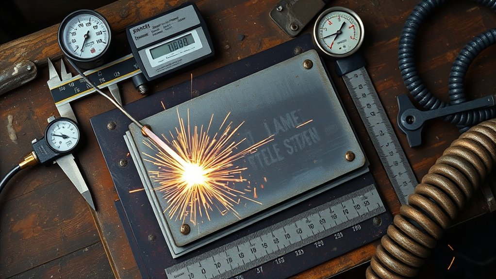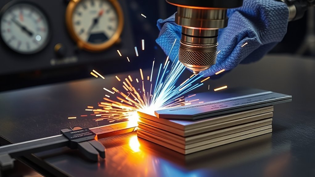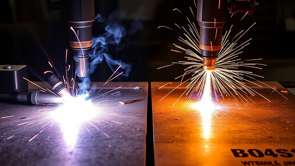
A 60 amp plasma cutter can handle sheet metal, brackets, plate, and many repair jobs, but the number on the front panel does not guarantee one universal cutting thickness. Input voltage, the machine’s real output range, torch and consumables, air quality, duty cycle, material, and operator technique all change the result. The safest way to set one up is to use the exact cut chart and electrical requirements in its manual, then confirm the settings on scrap.
Quick Answer
A 60 amp plasma cutter usually performs best on 240V, where a dual-voltage model can reach its full rated output. Some current machines advertise cuts near 7/8 inch steel, but clean-cut, pierce, and severance limits vary. Use the manufacturer’s cut chart for thickness, speed, air pressure, consumables, and duty cycle.
Key Takeaways
- Do not treat “60 amp” as a universal thickness or travel-speed rating. Compare the exact manual and cut chart.
- Many dual-voltage machines reduce output on 120V and reserve the full 60A range for 240V.
- Rated or recommended cut capacity is different from maximum severance and maximum pierce capacity.
- Stable, clean, dry air at the specified flowing pressure and CFM is essential for cut quality and consumable life.
- Tune with short test cuts and change one variable at a time while checking dross, bevel, kerf, and arc lag.
- Plasma cutting creates electrical, fire, fume, noise, UV, hot-metal, and compressed-air hazards, so proper PPE and ventilation are not optional.
What’s in This Article
- Understanding 60 Amp Plasma Cutter Capabilities
- Material Thickness Ranges at 120V vs. 240V
- Rated vs. Maximum Cutting Thickness Explained
- How to Set Travel Speed
- Air Supply Requirements
- Duty Cycle and Continuous Cutting
- Pilot Arc, Blowback, and Start Types
- Applications by Material and Thickness
- Safety, Power, and Protection
- How to Test and Tune Settings
- Frequently Asked Questions
- Conclusion
- Sources
At a Glance
| Time Required | About 10–20 minutes for setup, inspection, and test cuts before an important job |
| Difficulty | Intermediate; beginners should practice on scrap before cutting a finished part |
| Tools Needed | Plasma cutter, correct torch consumables, properly sized air compressor, regulator and filters, work clamp, scrap metal, PPE, and a fire extinguisher |
| Cost | No added cost if your air system, consumables, PPE, and test material are already available |
Understanding 60 Amp Plasma Cutter Capabilities
A 60A label describes the machine’s maximum output current under stated conditions. It does not, by itself, tell you the clean-cut thickness, severance thickness, pierce capacity, travel speed, or duty cycle. Manufacturers use different torches, power electronics, consumables, test methods, and marketing terms, so two machines with the same front-panel amperage can perform differently.
For a current model-specific example, the PrimeWeld CUT60 specifications list 20–30A output on 120V, 20–60A on 240V, a 60% duty cycle at maximum output, 5 CFM at 90 PSI air demand, and cutting capacity up to 7/8 inch steel. Those numbers are useful for that machine, not a universal chart for every 60A cutter.
Cut quality depends on several variables working together:
- Actual output: The current the machine can deliver on the connected input voltage.
- Material: Mild steel, stainless steel, and aluminum do not cut identically.
- Consumables: The nozzle orifice and consumable set must match the intended amperage and torch.
- Air or gas: Flow, pressure, cleanliness, and dryness affect the plasma column.
- Torch height and angle: Standoff and squareness affect bevel, kerf, and consumable wear.
- Travel speed: Moving too fast or too slowly creates different types of dross and bevel.
- Duty cycle: Thick plate and long cuts create more arc-on time and heat.
The machine’s cut chart is the starting point. The cut edge is the final test.
A non-touch pilot arc can make starts easier on rusty, painted, perforated, or expanded metal. It does not remove the need for a clean work-clamp connection, correct consumables, stable air, and proper torch technique.
Material Thickness Ranges at 120V vs. 240V
Many dual-voltage 60A-class plasma cutters reduce their output when connected to 120V. The exact reduction depends on the machine and circuit. A current CUT60 example limits output to 30A on 120V and allows the full 60A only on 240V. Other models may use different limits, so check the nameplate and manual before assuming what the machine can deliver.
| Input | What Usually Changes | Best Use |
| 120V | Lower maximum amperage, slower cutting on thicker metal, and potentially more circuit limitations | Sheet metal, lighter fabrication, portable repair, and occasional cuts within the manual’s reduced-output chart |
| 240V | Access to full rated output on many dual-voltage machines, better speed on thicker plate, and higher input-current requirements | Thicker plate, longer cuts, shop fabrication, and jobs that need the machine’s full capacity |
Input voltage is only one part of the setup. The branch circuit, breaker, receptacle, plug, conductor size, and extension cord must match the manufacturer’s electrical instructions and local code. A long or undersized cord can cause voltage drop and unstable operation.
Note: Do not estimate breaker size from the “60A” cutting output. Cutting amperage is not the same as input current. Use the nameplate and manual, and have a qualified electrician install or verify the circuit when needed.
Rated vs. Maximum Cutting Thickness Explained
Plasma-cutter capacity terms are not always standardized across brands. You may see “recommended,” “rated,” “quality,” “clean cut,” “maximum cut,” “severance,” and “pierce” ratings. Read the definitions in the specific manual instead of comparing labels alone.
Rated or Recommended Cut Thickness
This is the range intended for useful cut quality and reasonable speed under stated conditions. It is the better planning number for parts that need a controlled kerf, limited bevel, less dross, and less grinding. Even within this range, material condition, torch height, air quality, and operator speed can change the result.
Maximum or Severance Thickness
Maximum severance is the outer limit a machine may cut through under favorable conditions. It usually means slower travel, a wider and rougher kerf, more dross, greater bevel, more heat, and more cleanup. Severance capacity is useful for occasional demolition or separation cuts, but it is a poor production target.
Pierce Capacity vs. Edge Starts
Piercing starts in the middle of the plate and throws molten metal back toward the torch. That makes it harder on consumables than starting from an edge. A machine may sever a thickness that it should not pierce directly. Use an edge start on thick stock unless the manual gives a pierce setting for that thickness.
When piercing is allowed, follow the specified pierce height and delay. Hypertherm’s operating guidance warns that piercing too low can drive molten metal into the nozzle and shield, damaging consumables and the torch.
Speed and Quality Tradeoffs
As thickness approaches the machine’s upper limit, the arc takes longer to pass through the plate. Travel slows, lag lines become more pronounced, and the bottom of the cut is more likely to show dross or incomplete penetration. Staying within the recommended cut range gives you a larger tuning window and more repeatable results.
How to Set Travel Speed at Common Thicknesses
There is no reliable generic inches-per-minute chart for all 60A plasma cutters. Travel speed changes with the power source, torch, nozzle, material, thickness, gas, standoff, and whether you are cutting by hand or on a CNC table. Use the manufacturer’s chart as the starting point, then tune on scrap from the same material.
Hypertherm’s cut-quality guidance recommends checking the selected process, consumables, gas pressure or flow, torch-to-work distance, and cutting speed together. It also explains that high-speed dross forms when the torch moves too fast, while low-speed dross forms when it moves too slowly.
Starting a Test on 1/4-Inch Material
For 1/4-inch material, select the manual’s row for the exact alloy, consumable, and amperage. Set the flowing air pressure as specified, hold the recommended standoff or use the correct drag shield, and make a straight test cut. Do not copy a speed from a different brand merely because both machines say 60A.
Starting a Test on 1/2-Inch Material
At 1/2 inch, power, air delivery, and torch control become more important. Begin at the manual’s recommended setting, keep the torch square, and watch the sparks below the plate. They should pass through the kerf rather than spraying back toward the torch. If the cut does not fully separate, stop and correct the cause instead of repeatedly slowing down without checking air, consumables, input power, and standoff.
| Cut Symptom | Likely Cause | First Check |
| Small, hard bead of bottom dross with the arc trailing behind | Travel may be too fast | Reduce speed in small steps after confirming amperage, air, and standoff |
| Large, bubbly bottom dross and a wide kerf | Travel may be too slow | Increase speed slightly and recheck |
| One edge is consistently more beveled | Torch is not square, standoff is wrong, consumables are worn, or cut direction matters | Square the torch and inspect the nozzle orifice |
| Top spatter or molten metal thrown back at the torch | Speed may be too fast, the plate may exceed capacity, or the pierce setup may be wrong | Stop, inspect consumables, and use the correct pierce or edge-start method |
| Arc flicker, incomplete cut, or changing kerf | Air restriction, moisture, poor clamp contact, voltage drop, or worn consumables | Check flowing pressure, filters, hoses, input power, clamp location, and consumables |
Pro Tip: Mark a six-inch line on scrap and time the cut. That gives you an approximate hand-cut speed you can record, but use the edge condition, not the stopwatch alone, to judge the result.
Air Supply Requirements and Their Impact on Cut Quality
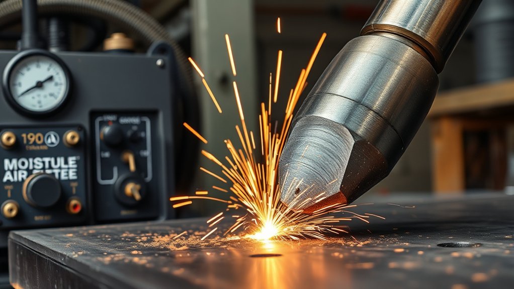
A plasma cutter needs enough air at the correct pressure while the torch is flowing. The static gauge reading before the trigger is pressed can look normal even when pressure collapses during a cut. Use the machine’s test-air or purge mode when available and set pressure under flow.
The required numbers vary. One current 60A model specifies 5 CFM at 90 PSI and an operating pressure range of 40–75 PSI. Another machine may require a different inlet pressure, flow rate, hose size, or filter arrangement. Match the compressor’s delivered CFM at the required pressure, not only its tank size or advertised peak horsepower.
Air must also be clean and dry. Hypertherm states that air quality directly affects cut quality, performance, and consumable life. Moisture, oil mist, rust, and particles can destabilize the arc, reduce speed, damage internal components, and shorten electrode and nozzle life.
- Drain the compressor tank and moisture separators regularly.
- Use particulate and coalescing filtration when the air system carries water or oil.
- Keep hoses and quick-connect fittings large enough to avoid flow restriction.
- Repair leaks and avoid excessive hose length.
- Do not exceed the cutter’s maximum inlet pressure.
- Replace filter elements according to their condition and service schedule.
Warning: Never use oxygen as a substitute for compressed air unless the plasma system is specifically designed and approved for that gas. Follow the manufacturer’s gas, regulator, hose, and pressure instructions.
Duty Cycle Considerations for Continuous Cutting
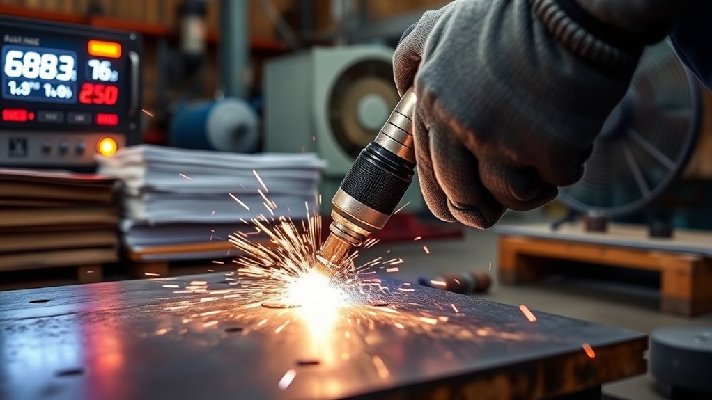
Duty cycle tells you how long the power source can operate at a stated output and ambient condition within a 10-minute period without overheating. Miller explains that a 60% duty cycle means six minutes of cutting followed by four minutes of cooling at the rated condition.
Do not assume all 60A machines have a 60% or 80% duty cycle. Read the rating plate or manual. Duty cycle normally increases when you reduce amperage, but the actual curve is model-specific. High ambient temperature, blocked cooling passages, dust, low input voltage, and repeated long cuts can cause thermal protection to activate sooner.
- Estimate arc-on time: Long cuts on thick plate can use most of the available duty cycle in one pass.
- Keep cooling paths clear: Leave space around the machine and clean vents as the manual directs.
- Watch warning indicators: If thermal protection stops output, leave the machine powered as instructed so its fan can cool it.
- Do not bypass protection: Repeated shutdown is a sign to reduce workload, lower amperage when appropriate, improve ventilation, or use a higher-duty machine.
Torch Technology: Pilot Arc, Blowback, and Start Types
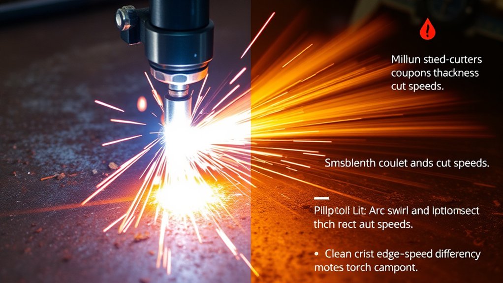
Torch terminology can be confusing because pilot arc, continuous pilot, blowback, high-frequency start, drag cutting, and 2T/4T describe different functions.
- Pilot arc: Creates an arc inside the torch before the main cutting arc transfers to the workpiece. It helps start on rough, coated, or rusty surfaces.
- Continuous pilot arc or auto-restart: Keeps or restrikes the pilot across gaps, which helps on mesh, grating, and expanded metal. Frequent pilot operation can still consume parts, so use the correct mode for the job.
- Blowback start: Uses a moving electrode mechanism and can provide a non-high-frequency start. On a properly designed machine, that is helpful for CNC integration because it reduces high-frequency interference risk.
- High-frequency start: Uses a high-voltage, high-frequency pulse to initiate the arc. It can work well for manual cutting but requires careful grounding and may be less suitable near sensitive electronics.
- Drag cutting: Uses a shield or consumable design that allows the torch to contact the work while maintaining the intended internal spacing. Do not drag an unshielded nozzle unless the manual allows it.
- 2T/4T trigger modes: In 2T you hold the trigger while cutting. In 4T the trigger can latch for a long cut, reducing hand fatigue.
A pilot arc does not automatically mean the machine is CNC-ready. CNC use also depends on torch type, start input, arc-ok signal, voltage-divider output, electrical isolation, connector pinout, grounding, and the table controller’s requirements.
Products Worth Considering

【Non-Touch Pilot Arc Function】The ARCCAPTAIN 55A plasma cutter features a pilot arc function. It utilizes a high-frequency non-touch arc starting mode. The torch head does not need to touch the metal plate, reducing energy consumption during non-cutting work, minimizing electrode burning, and extending service life. NOTE: Do not switch voltages until the screen turns off and the fan stops.

【Non-Touch Pilot Arc Function】The plasma cutter features a high frequency non-touch arc starting mode. It allows for cutting steel surfaces with dirt, rust or coatings. The torch head does not need to touch the metal plate, reducing energy consumption, minimizing electrode burning, and extending service life. NOTE: DO NOT power on until the screen turns off and the fan stops working!
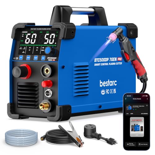
[Smart APP Remote Control Up to 98FT] Control your plasma cutter from up to 98 ft (30 m) away via Bluetooth APP. Adjust cutting current, switch cutting modes, save preferred settings, monitor operating status, and check error codes directly from your phone. Reduce trips back to the machine and work more efficiently—ideal for workshops, auto repair, farms, garages, and DIY projects.
Real-World Applications by Material and Thickness
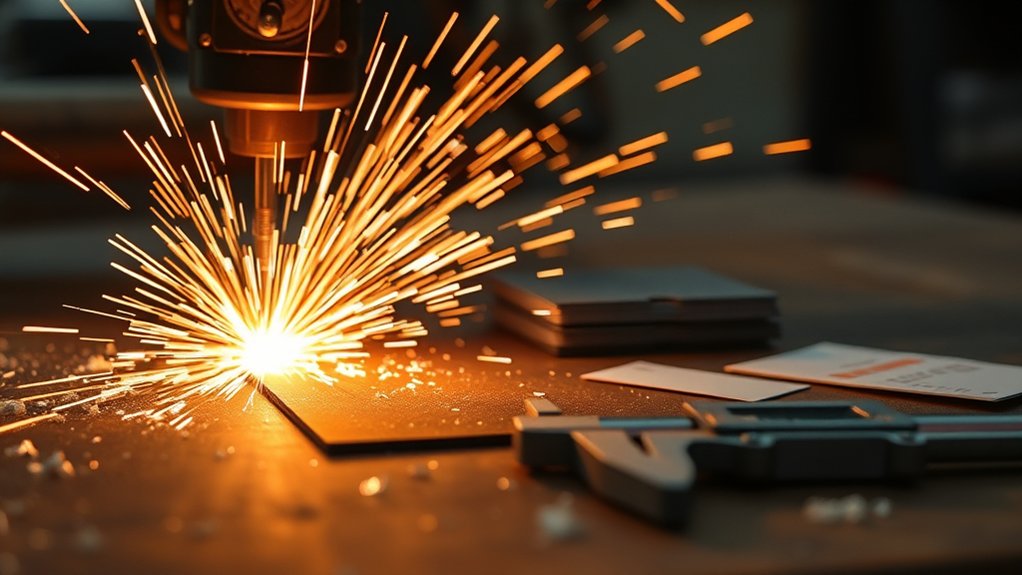
A 60A-class cutter is versatile, but the most productive jobs normally stay comfortably inside the machine’s recommended capacity. The ranges below describe common applications, not guaranteed limits.
- Automotive restoration: Body patches, floor pans, brackets, tabs, exhaust pieces, and repair plates. Reduce amperage and use a guide or drag shield on thin sheet to control kerf and heat.
- General fabrication: Mild-steel plate, stainless brackets, base plates, gussets, and shop fixtures. Use the material-specific cut chart and expect stainless or aluminum edges to look different from mild steel.
- Farm and equipment repair: Rusty plate, seized parts, guards, and field repairs. Pilot arc can help on surface contamination, but clean a solid clamp area and remove hazardous coatings before cutting.
- Metal art: Curves, signs, silhouettes, and expanded metal. A smaller nozzle, lower amperage, guide, or CNC table may provide better detail than running at the maximum 60A output.
- Thick-plate severing: Occasional separation cuts near the machine’s upper limit. Use an edge start where possible and expect slower travel and more cleanup than a rated-quality cut.
Air plasma can cut electrically conductive mild steel, stainless steel, aluminum, copper, brass, and other conductive metals. Material type changes edge chemistry and appearance. For example, air plasma can leave oxidation or nitriding on cut surfaces, so clean and prepare the edge before a critical weld.
Safety, Power, and Protection Features for Reliable Operation
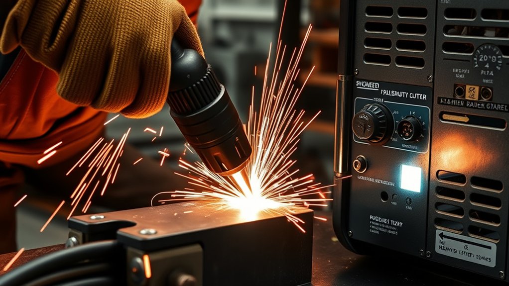
Plasma cutting exposes you to hot metal, sparks, molten slag, ultraviolet and infrared radiation, fumes, gases, noise, electrical shock, fire, and compressed-air hazards. OSHA’s hot-work guidance identifies these hazards and calls for suitable eye and face protection, protective clothing, gloves, footwear, ventilation, and other controls based on the job.
Warning: Never plasma-cut a used drum, tank, pipe, or sealed container unless it has been properly cleaned, disconnected, vented, and made safe by qualified procedures. Residue or trapped vapor can explode or release toxic fumes.
- Eye and face protection: Wear a plasma-cutting shield or helmet with the lens shade specified by the machine manual and applicable safety rules, plus safety glasses with side protection.
- Skin and clothing: Wear flame-resistant clothing that covers your skin, leather gloves, and appropriate boots. Avoid synthetic fabrics that can melt.
- Hearing: Use hearing protection selected for the measured noise exposure in your shop.
- Ventilation: Use local exhaust or suitable mechanical ventilation. Coated, galvanized, stainless, lead-, cadmium-, chromium-, or beryllium-containing materials require special controls.
- Fire prevention: Remove or shield combustibles, control sparks below and behind the cut, keep a suitable extinguisher ready, and use a fire watch when conditions require it.
- Electrical safety: Keep the machine and work area dry, inspect leads and insulation, connect the work clamp to clean metal near the cut, and disconnect input power before service.
- Workpiece support: Support the metal so the cut piece cannot fall, trap the torch lead, or strike you.
OSHA’s welding and cutting requirements also address fire prevention, used containers, eye protection, and ventilation. Workplace rules can be stricter than a general guide, so follow your employer’s hazard assessment and local requirements.
Machine protection features such as overtemperature shutdown, overcurrent protection, input-surge protection, air-pressure sensing, and post-flow cooling can reduce equipment damage. They do not replace correct circuits, dry air, ventilation, maintenance, or safe operator behavior.
Products Worth Considering

Lens Technology- IR 5.0 Filter Green Lens are ANSI & CSA compliant, with 99% protection from UV rays to reduce eye fatigue and prevent damage.

EYE & FACE PROTECTION - Jackson Safety’s GPL550 Safety Goggles with a detachable flip-up face shield ensure your safety in the most demanding environments with indirect vents and anti-fog coating

Mirrored shade 5 lenses
How to Test and Tune Your 60A Plasma Cutter Settings
Test cuts provide more reliable settings than a generic chart because they account for your exact machine, air system, consumables, power supply, material, and hand speed.
- Read the manual first. Find the row for the material, thickness, consumable, and input voltage. Confirm the circuit and air requirements.
- Inspect the machine and torch. Check the power lead, work lead, torch lead, consumable stack, nozzle orifice, filter bowl, and regulator.
- Prepare the work. Remove flammable materials, identify coatings, support the plate, expose clean metal for the clamp, and put on PPE.
- Set air under flow. Use test-air or purge mode and set the exact pressure in the manual. Confirm the compressor can maintain the required CFM.
- Set amperage and standoff. Match the installed consumables. Use the specified drag shield or torch-to-work distance.
- Make a short straight cut. Use scrap from the same material and thickness. Keep the torch square and move steadily.
- Inspect the edge. Check complete separation, top-edge rounding, bevel, kerf width, dross type, lag lines, and discoloration.
- Change one variable. Adjust speed first when the other settings match the manual. Make small changes and test again.
- Record the result. Note machine, voltage, amperage, consumables, flowing pressure, material, thickness, approximate speed, and edge quality.
Pro Tip: Keep separate records for new and partly worn consumables. A setting that works with a fresh nozzle may need a small standoff or speed correction as the consumables wear.
Quick Troubleshooting Order
When cut quality suddenly changes, check the system in this order: correct consumables and assembly, consumable wear, work-clamp contact, input voltage, flowing air pressure, air contamination, torch angle and height, then travel speed. This order prevents you from chasing speed when the real problem is air, power, or worn parts.
Frequently Asked Questions
Can I use a generator to power a 60A plasma cutter?
Only when the plasma-cutter manufacturer permits generator use and the generator can supply the required voltage, continuous current or kVA, frequency, receptacle, grounding arrangement, and acceptable power quality. Do not size it from the 60A cutting output. Use the manual’s input specifications and ask the manufacturer or a qualified electrician when the guidance is unclear.
What consumable lifespan should I expect at 60 amps?
There is no dependable universal number. Life depends on the torch, consumable design, number of starts, pierce height, material thickness, air quality, amperage, standoff, and technique. Inspect the nozzle orifice and electrode according to the manual, and replace worn parts before they damage cut quality or the torch.
How noisy is a 60A plasma cutter during operation?
Noise varies with amperage, airflow, material, thickness, torch height, table design, and the room. Treat plasma cutting as a hearing-risk process, measure exposure when required, and use hearing protection selected for the actual noise level.
Will a CNC table require different torch leads or interfaces?
Often, yes. Confirm whether the cutter supports a machine torch, remote start, arc-ok signal, divided arc voltage, and the connector pinout your table needs. A non-high-frequency blowback start can reduce interference risk, but correct grounding, shielding, isolation, and manufacturer-approved wiring are still necessary.
How does altitude affect plasma cutter performance and settings?
Higher altitude reduces air density and may affect cooling, compressor delivery, and arc performance. Follow the manufacturer’s altitude or derating limits. Do not raise pressure beyond the allowed range to compensate. Confirm flowing pressure, use test cuts, and contact the manufacturer when operating above the stated elevation limit.
Can a 60 amp plasma cutter cleanly cut 1-inch steel?
Do not assume it can. Some machines may advertise severance near that thickness, while their recommended clean-cut or pierce rating is lower. Check the exact cut-capacity definitions and chart for your model. For repeatable one-inch plate work, choose a system with a documented quality-cut rating at that thickness.
What breaker size does a 60A plasma cutter need?
Breaker size is model- and voltage-specific. A current dual-voltage CUT60 example lists a 30A breaker on 120V and a 50A breaker on 240V, but another machine may differ. Follow the nameplate, manual, plug configuration, conductor requirements, and local electrical code.
Conclusion
You will get the best results from a 60A plasma cutter by treating its manual as the source of truth and its cut edge as the final check. Use 240V when the machine requires it for full output, stay within the documented cut and pierce ranges, supply clean dry air at the correct flowing pressure, and respect duty cycle. Short test cuts, sound safety controls, and a written settings log will save more time than guessing from a generic thickness or speed chart.
Sources
- PrimeWeld CUT60 specifications — current model example for dual-voltage output, duty cycle, air demand, breaker size, start type, and stated cutting capacity.
- Hypertherm: Improve plasma cut quality — cut-chart use, consumables, standoff, speed, bevel, and dross troubleshooting.
- Hypertherm: Air filtration for air plasma systems — effects of moisture and contamination on performance and consumable life.
- Miller: Plasma cutting tips — duty-cycle definition and setup guidance.
- OSHA: Hot-work PPE selection — plasma-cutting hazards and protective equipment.
- OSHA 29 CFR 1910.252 — fire prevention, used containers, eye protection, and ventilation requirements for welding and cutting.