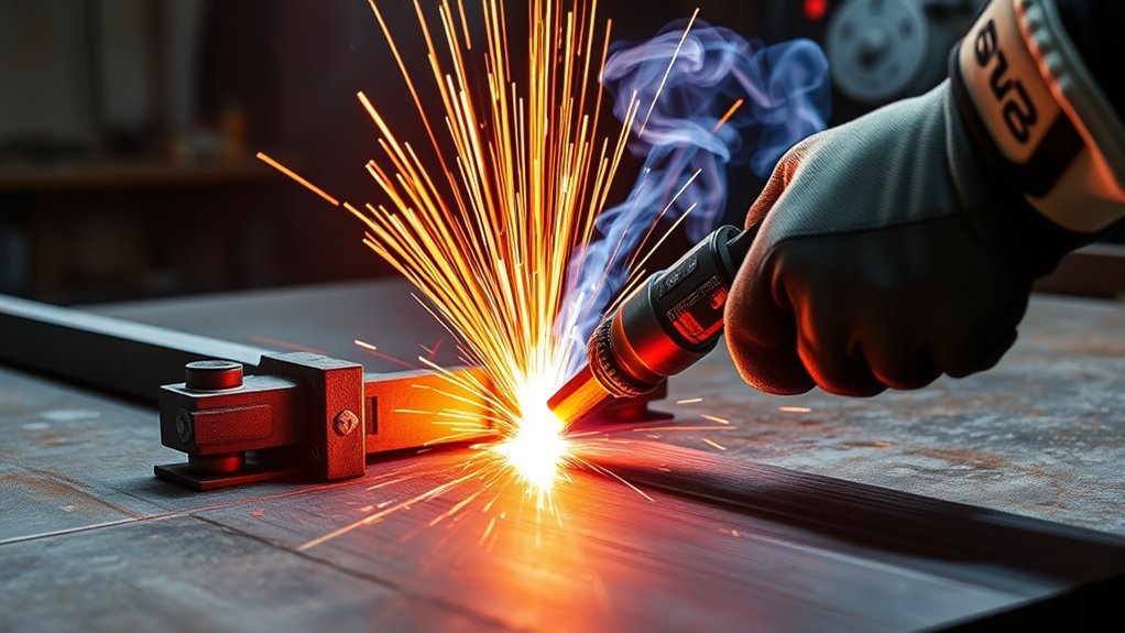
Plasma cutting aluminum works well when you treat the setup as a matched system: material thickness, amperage, travel speed, gas, nozzle size, torch height, and air quality all affect the cut. Aluminum also sheds heat quickly, so you need enough power for full penetration without moving so slowly that the edge overheats, bevels, or loads up with dross.
Quick Answer
Yes, you can plasma cut aluminum if the metal is clean, electrically grounded, and matched to the correct cut chart. Start with the manufacturer’s amperage, nozzle, gas, speed, and standoff settings, then tune with a short test cut. Good settings leave steady sparks, full penetration, light dross, and a smooth edge.
Key Takeaways
- Use your plasma cutter’s cut chart first. Aluminum settings vary by machine, torch, consumables, gas, and whether you cut by hand or CNC.
- For cleaner edges, balance amperage and speed. Too slow causes dross and heat buildup; too fast can leave uncut ligaments.
- Dry, clean air is fine for many shop cuts, but nitrogen or argon-hydrogen systems can improve edge quality on higher-end machines.
- Torch height controls bevel. Keep a steady standoff and avoid dragging the nozzle unless your torch and consumables are designed for contact cutting.
- Water tables reduce dust and glare, but aluminum can create hydrogen hazards in some setups. Follow the table and plasma-system manufacturer’s safety procedure.
At a Glance
| Time Required | 5 to 15 minutes for setup and test cuts; longer for thick plate or CNC jobs |
| Difficulty | Moderate. Thin sheet is forgiving; thick aluminum needs better power, gas control, and speed discipline |
| Tools Needed | Plasma cutter, correct consumables, clean dry air or specified gas, ground clamp, PPE, straightedge or CNC table, scraper or deburring tool |
| Cost | Usually low if you own the cutter; main costs are consumables, gas or compressed air treatment, and finishing supplies |
Can You Plasma Cut Aluminum?
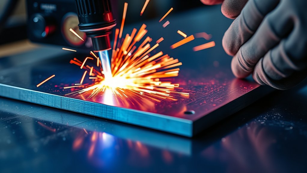
Yes, you can plasma cut aluminum because aluminum is electrically conductive. The arc melts the metal and the gas jet blows the molten aluminum out of the kerf. With the right setup, you can cut sheet, plate, brackets, signs, repair panels, and CNC profiles.
The main challenge is not whether aluminum will cut. The challenge is keeping the edge clean. Aluminum conducts heat quickly, forms oxide on the surface, and can show dross, bevel, top spatter, and rough edges if your settings drift.
For best results, start with your machine’s cut chart. The chart is more reliable than any general online setting because it is based on your torch, consumables, gas, material thickness, amperage, pierce height, cut height, and travel speed.
Warning: Plasma cutting is hot work. Wear proper eye and face protection, flame-resistant clothing, gloves, and hearing protection. Keep combustibles away, use adequate ventilation, and follow your shop’s fire-watch rules and the cutter manufacturer’s manual.
Safety and Setup Before Cutting Aluminum
Before you tune cut quality, make the work area safe. Plasma cutting produces bright arc radiation, molten metal, sparks, noise, fumes, and electrical hazards. OSHA’s eye and face protection standard lists minimum shade guidance for plasma arc cutting, and OSHA’s welding and cutting requirements cover ventilation and fire prevention.
- Protect your eyes and face: Use a welding helmet or plasma-rated face shield with the correct shade for the amperage. Do not rely on clear safety glasses alone.
- Ventilate the area: Use local exhaust or mechanical ventilation when fumes can build up, especially indoors or in tight spaces.
- Control fire risk: Sweep the area, remove flammables, keep an extinguisher ready, and use a fire watch when sparks can reach combustible material.
- Ground to clean metal: Clamp the work lead to bare aluminum or a clean table contact point. Oxide, paint, anodizing, and dirt can make arc starts unstable.
- Keep air dry: Drain the compressor, use a water separator, and add a dryer if you see arc sputter, heavy dross, or rapid consumable wear.
Simple Step-by-Step Setup
- Clean the cut path. Remove paint, oil, heavy oxide, adhesive, and marker residue near the cut line.
- Install the right consumables. Match the nozzle, electrode, swirl ring, shield, and retaining cap to the amperage and torch type.
- Check air or gas supply. Set pressure and flow to the cutter manual. Do not guess from another machine’s chart.
- Set amperage from the cut chart. Use the chart for the nearest aluminum thickness and cutting process.
- Set standoff. Use the recommended cut height. For many hand torches, this is a small standoff or a drag-shield setup, depending on the consumables.
- Make a short test cut. A 2 to 3 inch coupon tells you more than a full production cut.
- Read the edge. Tune speed, height, and amperage only after you inspect penetration, dross, bevel, and spark direction.
Pro Tip: Change one setting at a time. If you adjust amperage, speed, and height together, you will not know which change improved or worsened the cut.
Thickness Ranges and Recommended Power
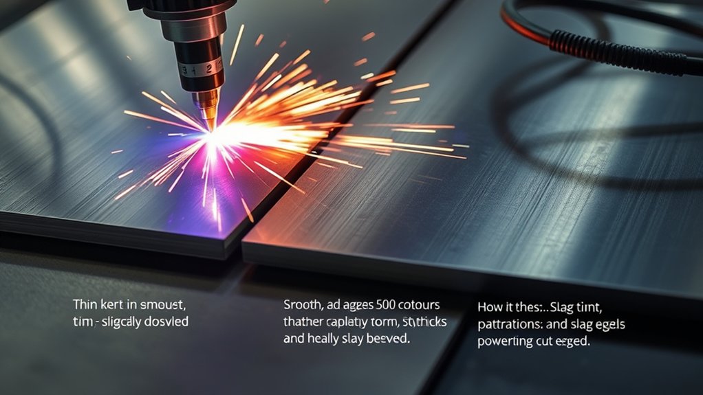
For most aluminum jobs, match thickness to amperage, travel speed, nozzle rating, and standoff. Use the ranges below as a starting point only. Your cutter’s chart always wins because different machines produce different arc energy at the same amp setting.
Thin aluminum sheet needs fast travel and controlled heat. Thick aluminum needs more current, a larger rated nozzle, slower travel, and a cleaner air or gas supply. If the arc fails to pierce, leaves uncut webs, or throws sparks upward, the job may be too thick for the machine or the speed may be too high.
| Aluminum Thickness | Starting Amperage Range | Setup Notes |
|---|---|---|
| Up to 1/8 in | 25 to 35 A | Move quickly. Use a smaller nozzle and avoid lingering at corners. |
| 3/16 to 1/4 in | 35 to 45 A | A common shop range. Test for full penetration and light bottom dross. |
| 5/16 to 3/8 in | 45 to 60 A | Use the proper nozzle rating and watch for bevel from height drift. |
| 7/16 to 1/2 in | 55 to 80 A | Needs strong air flow or specified gas, steady standoff, and slower travel. |
| Over 1/2 in | 80 A and up, if rated | Use a machine rated for the thickness. Consider CNC, edge start, or saw/waterjet if quality matters. |
Watch the sparks during the test cut. A good cut usually sends sparks downward with a slight trailing angle. Sparks that blow back toward the top often mean poor penetration, travel speed that is too fast, or not enough current for the thickness.
Products Worth Considering
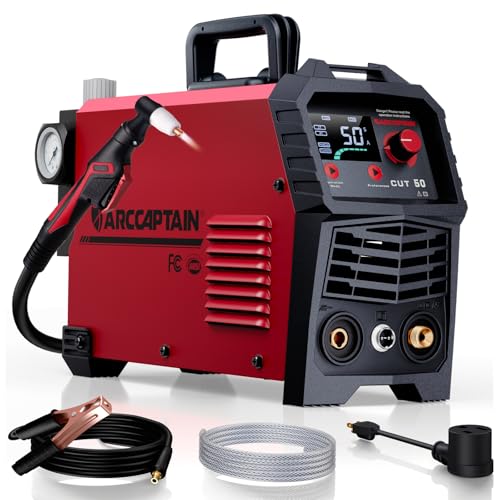
【Powerful Cutting Ability】Switch effortlessly between 110V and 220V for home or workshop use. Achieve professional 1/2" clean cuts on steel, aluminum, and copper with advanced LGBT technology. Perfect for DIY projects and heavy-duty tasks. Recommended maximum cutting thickness: 12mm @ 35A / 110V / 55 PSl; 18mm @ 50A / 220V / 75 PSI. Note: Requires compressed air (compressor sold separately).

PT31 Plasma Torch: standard length: 16ft; air pressure: 4.5-5.5bar; duty cycle for 60% with 30A

S45 Plasma Torch Body Head
Gas Selection for Clean Edges
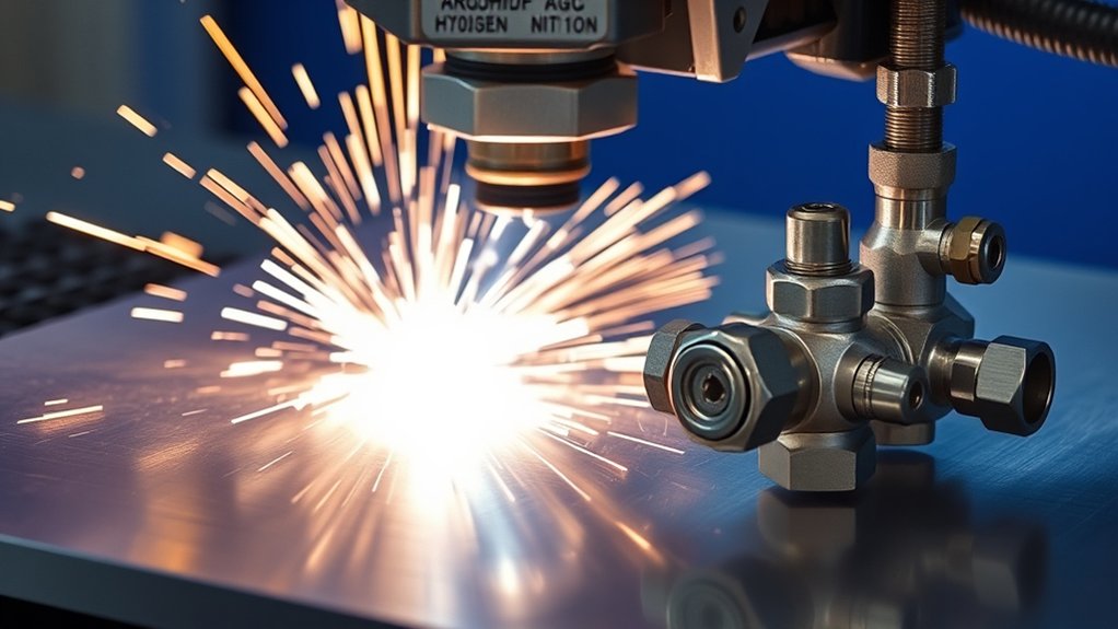
Gas choice affects arc stability, edge color, oxide, dross, and consumable life. For many handheld plasma cutters, clean dry compressed air is the standard and most economical choice. It cuts aluminum well enough for brackets, repair panels, and general fabrication, but the edge may need light cleanup.
Higher-end CNC and high-definition systems may use nitrogen, argon-hydrogen, water shield, or other matched plasma and shield-gas combinations. Do not mix gases outside the system’s manual. The torch, consumables, gas console, and table design must be rated for the gas you plan to use.
Products Worth Considering

Desiccant Air Dryer System: Engineered with a compressor desiccant air filter dryer system that effectively traps water vapor, oil aerosols, and dirt particles from the air supply. This unit functions as a reliable air line dryer, helping to prevent moisture-related damage to pneumatic tools and ensuring smoother operation for workshop projects.

【Designed for Drying】The Desiccant Air Dryer allows the Air to be Thoroughly Dried and Cleaned before it Enters your Pneumatic Tools. The Desiccant Beads need to be Added to the Metal Bowl. When it needs to be Replaced, the Beads will Change from Blue to Pink.
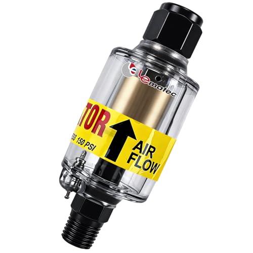
Moisture Protection: 1-micron reusable element removes air compressor oil and water from compressed air systems; essential for precise spray painting and plasma cutting
Compressed Air vs. Nitrogen vs. Mixed Gas
- Compressed air: Best for cost and shop convenience. Use clean, dry air to reduce arc sputter and consumable damage.
- Nitrogen: Often used on systems designed for cleaner nonferrous cutting. It can reduce oxidation compared with ordinary shop air on the right equipment.
- Argon-hydrogen blends: Used on some industrial systems for thicker aluminum and high-quality edges. Use only when the equipment maker specifies it.
- Oxygen: Common for cutting carbon steel on some machines, but it is usually not the first choice for general aluminum edge quality unless your system’s chart calls for it.
Air Quality and Dryer Setup
Moisture and oil in the air stream can cause rough edges, unstable starts, and fast consumable wear. Drain the compressor tank, use a water separator, and keep filters serviced. If your shop is humid or you cut for long sessions, a refrigerated or desiccant dryer can make cut quality more repeatable.
When the cut suddenly gets worse with no setting change, check air quality before blaming the torch. Water in the line often shows up as sputtering, extra top spatter, heavy dross, and a dirty nozzle orifice.
Note: Gas recommendations are system-specific. Never assume a gas blend is safe because another cutter uses it. Follow the plasma cutter, torch, gas console, and water-table manuals together.
Nozzle Size, Amperage, and Line Speed
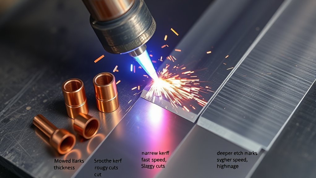
Nozzle size, amperage, and travel speed work together. A nozzle rated for 30 A should not be pushed at 60 A, and a high-amp nozzle may produce a wider, less controlled kerf on thin aluminum. Match the nozzle to the amperage range in the manual.
Travel speed is just as important. Too slow gives the arc too much time in one spot, which widens the kerf and creates bottom dross. Too fast can leave uncut sections, heavy striations, and sparks that trail far behind or blow back upward.
- Thin sheet: Use lower amperage, a smaller rated nozzle, and faster travel.
- 1/4-inch plate: Many shop machines land around the 35 to 45 A range, but the correct value depends on the cut chart.
- Thicker plate: Increase amperage only if the torch and nozzle are rated for it, then slow travel enough to maintain full penetration.
For long cuts, inspect consumables often. A worn or oval nozzle makes the arc wander, increases bevel, and changes kerf width even if your machine settings stay the same.
Torch Height, Voltage, and Bevel Control
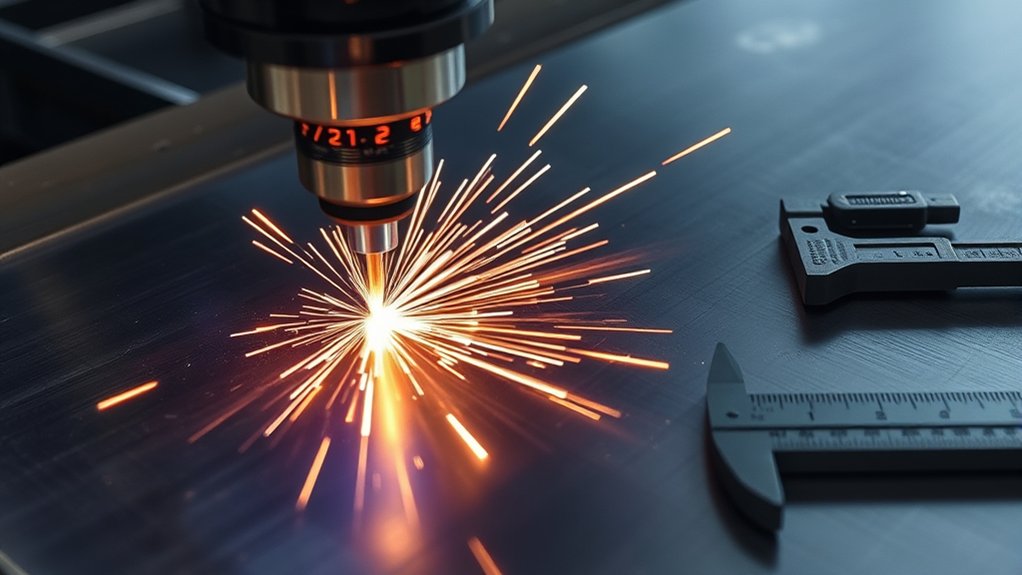
Torch height is one of the fastest ways to change bevel. If the torch is too high, the arc spreads before it reaches the plate, which can widen the top of the kerf and make the edge less square. If the torch is too low, spatter can damage the nozzle and the arc can become unstable.
For CNC systems, torch height control uses arc voltage to hold a steady standoff after the pierce. Higher voltage usually raises the torch; lower voltage usually lowers it. Make small changes and measure the cut face instead of guessing from the top edge only.
For hand cutting, keep the torch angle consistent. Hold it as close to 90 degrees as possible unless you are intentionally making a bevel. A small lean can create taper from one side of the cut to the other.
Clean aluminum cuts come from steady motion, steady height, and clean consumables. A perfect amperage setting will not save a cut if the torch keeps bobbing up and down.
Piercing Technique and Consumable Life
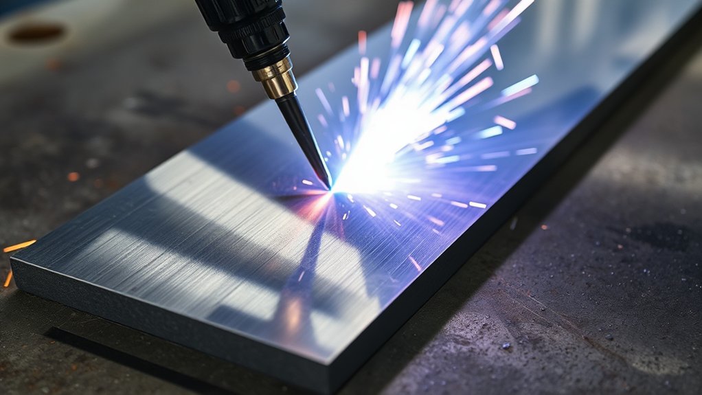
Piercing is hard on consumables because molten aluminum can blow back toward the nozzle. Use the pierce height and pierce delay in the cut chart. On CNC systems, pierce height is often higher than cut height so the torch can survive the molten splash before it lowers into the cut.
For hand cutting, angle the torch slightly at the start if your manual allows it, then straighten as the arc breaks through. On thicker aluminum, an edge start may protect consumables and give a cleaner beginning than piercing directly in the middle of the plate.
- Start high enough: Use the recommended pierce height or drag-shield method for your torch.
- Wait for breakthrough: Do not move too soon. Early motion can leave an uncut tab at the start.
- Move to cut height: Once the arc is through, settle into the correct standoff and speed.
- Inspect the nozzle: Replace it when the orifice becomes oval, nicked, or visibly worn.
Managing Dross and Surface Oxidation
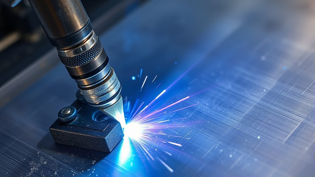
Dross is your feedback. Aluminum that cuts cleanly should have full penetration and only light, removable dross. Heavy, hard dross usually means the arc is not focused correctly for the speed, height, or amperage.
- Bottom dross: Often caused by moving too slowly, using too much heat, cutting too high, or using worn consumables.
- Top spatter: Often caused by piercing too low, dirty material, moisture in the air, or a damaged nozzle.
- Uncut ligaments: Often caused by moving too fast, using too little current, or cutting material beyond the machine’s rated capacity.
- Heavy bevel: Often caused by torch height drift, worn consumables, wrong speed, or an angled hand torch.
- Rough, gray edge: Often caused by air quality, oxide, incorrect gas, or an unstable arc.
After cutting, remove light dross with a scraper, file, flap wheel, or fine abrasive pad. Avoid aggressive grinding if you need a sharp, accurate edge for fit-up.
Water Tables, Water Shields, and Safety
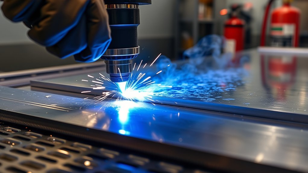
Water tables and water shields can reduce dust, glare, noise, and heat distortion. They can also help collect dross and make cleanup easier. When they are designed and maintained correctly, they are useful for aluminum plasma cutting.
The safety concern is hydrogen. Aluminum cutting over or under water can create trapped gas in some table setups, especially under plates, inside cavities, or in poorly ventilated areas. Do not treat a water table as a simple bucket of water. Treat it as part of the cutting system.
Underwater Cutting Risks
Before cutting aluminum on a water table, read the table manufacturer’s aluminum-cutting procedure. Confirm the approved gas, water level, ventilation, slat spacing, part-removal process, and maintenance routine. Do not use hydrogen-containing gas blends underwater unless the equipment maker specifically approves that setup.
Hot work should not be performed where an explosive atmosphere exists or may develop. If your table can trap gas under the workpiece, stop and correct the setup before cutting.
Water Shield Benefits
A properly managed water shield can cool the kerf, reduce airborne dust, and limit glare. It can also help thin aluminum stay flatter by pulling heat away from the cut zone. The benefit depends on the table design, water level, part geometry, and gas system.
Keep the water clean enough for the process, remove sludge as recommended, and do not let small parts sit under larger plates where gas pockets can collect.
Hydrogen Management Tips
- Follow the table manual: Use only approved gases, water heights, and operating procedures.
- Vent trapped spaces: Avoid cutting over cavities or stacked plates that can hold gas.
- Remove parts promptly: Do not let cut pieces trap bubbles under the plate.
- Maintain airflow: Use the ventilation system specified for the table and shop.
- Stop if you smell, hear, or see abnormal behavior: Popping, unusual bubbling, arc instability, or trapped pockets should be investigated before work continues.
Design, Fixturing, and Heat Management
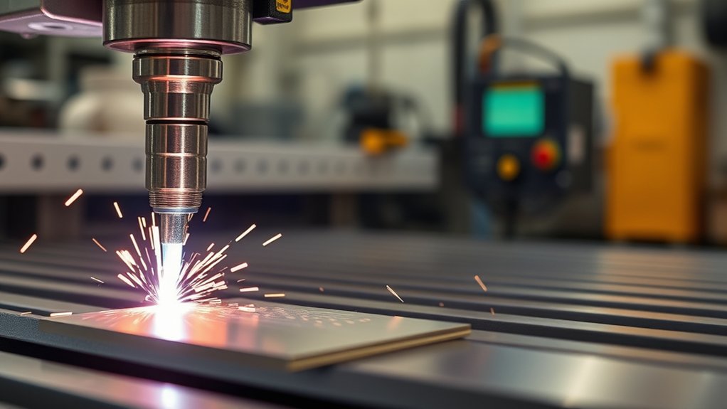
Aluminum cuts fast, but it can still warp when heat builds in one area. Good design and fixturing help keep the part accurate.
Use smooth lead-ins, avoid tiny unsupported tabs, and keep enough space between nearby features so the plate does not overheat. When possible, cut small internal features first, then larger outside contours. On a CNC table, rotate the cut sequence so heat is spread around the part instead of concentrated in one corner.
Clamp thin sheet enough to keep it flat, but do not clamp so tightly that thermal movement has nowhere to go. For hand cutting, use a straightedge or guide when the edge needs to be accurate.
Always connect the ground clamp to clean bare metal. Aluminum oxide, anodizing, paint, and dirt increase resistance and can make the pilot transfer erratic. A stable circuit gives you a steadier arc and a cleaner kerf.
Cut Charts for Common Aluminum Gauges and Plates
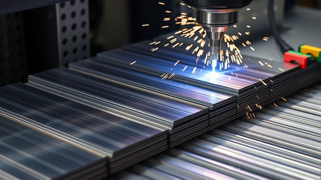
The chart below gives practical starting points, not final machine settings. Use it to understand the relationship between thickness, amperage, and speed. Then compare it with your plasma cutter’s cut chart before cutting real parts.
Gauge-To-Amp Settings
Thin gauges need less heat and faster motion. Plate needs more current and enough dwell time for the arc to cut through. If you increase amperage without increasing speed, you can make the kerf wider and create more bottom dross.
If you change consumables, treat the machine like a new setup. A fine-cut nozzle, drag shield, mechanized shield, and high-amp nozzle can all cut differently at the same amp number.
Thickness-Speed Lookup
| Thickness | Starting Amperage | Starting Speed Range |
|---|---|---|
| ≤ 1/8 in | 25–35 A | Fast hand travel or chart speed |
| 3/16–1/4 in | 35–45 A | Moderate travel; tune by dross and sparks |
| 5/16–3/8 in | 45–60 A | Slower than 1/4 in; verify full penetration |
| 7/16–1/2 in | 55–80 A | Slow, steady travel; machine rating matters |
| > 1/2 in | 80 A+ if rated | Use manufacturer chart, CNC control, or another cutting process |
Use this test-cut procedure before production work:
- Set current at the chart value for the metal thickness.
- Cut a 2 to 3 inch coupon in scrap from the same material.
- Check the bottom edge for dross and uncut webs.
- Check the cut face for bevel and rough striations.
- Adjust speed first, then height, then amperage if needed.
- Record the final settings for that machine, material, and consumable set.
Troubleshooting Common Aluminum Cut Problems
| Problem | Likely Cause | Fix |
|---|---|---|
| Heavy bottom dross | Too slow, too high, worn nozzle, or damp air | Increase speed slightly, verify standoff, inspect consumables, dry the air supply |
| Cut does not go through | Too fast, too little amperage, poor ground, or machine under-rated | Slow down, check the ground, use chart amperage, or switch to a higher-capacity cutter |
| Wide top kerf | Torch too high, too much heat, or slow speed | Lower to chart height, increase speed, or reduce amperage if the chart allows |
| Strong bevel on one side | Angled torch, worn nozzle, or cut-direction effect | Hold the torch square, replace the nozzle, and keep the good side of the kerf on the part side |
| Erratic arc starts | Dirty plate, anodizing, paint, weak work clamp, or bad consumables | Grind to bare metal, move the clamp closer, clean the plate, and inspect consumables |
Frequently Asked Questions
How do shop humidity and air dryer types affect aluminum cut quality?
Humidity adds moisture to the air stream, which can make the arc unstable, increase dross, and wear consumables faster. A water separator helps, but humid shops often need a refrigerated or desiccant dryer for steady results during long cutting sessions.
What post-cut finishing removes micro-burrs without rounding sharp edges?
Use a hand scraper, fine file, fine Scotch-Brite pad, light deburring wheel, or low-pressure bead blast. Keep the tool flat and use short passes. Avoid aggressive flap discs if the part needs a crisp edge or tight fit-up.
How does paint or anodizing near the cut affect arc stability?
Paint, anodizing, adhesive, and heavy oxide can raise surface resistance and make the pilot arc transfer poorly. Grind or sand the work-clamp area and the start area to bare aluminum for steadier starts and cleaner cuts.
Can CNC lead-in and lead-out geometry reduce edge waviness on tight contours?
Yes. Use smooth lead-ins, avoid starting on the finished edge, and give the torch room to stabilize before it reaches the part profile. On tight contours, reduce speed only as much as the cut chart allows so the corner does not overheat.
What maintenance schedule prevents nozzle drift and inconsistent kerf width?
Inspect the nozzle and electrode before each cutting session, drain moisture from the air system daily, verify torch height before important jobs, and run a short kerf test when accuracy matters. Replace consumables when the orifice is oval, nicked, or causing visible bevel.
Conclusion
You can plasma cut aluminum cleanly when you stop guessing and work from a repeatable setup. Start with the manufacturer’s cut chart, clean the plate, clamp to bare metal, use dry air or the specified gas, and match nozzle size to amperage. Then tune speed and torch height with a short test cut.
For thin aluminum, move fast enough to control heat. For 1/4-inch and thicker plate, use enough current for full penetration and slow down only as much as needed. If dross, bevel, or rough edges show up, read the cut face before changing settings. Clean consumables, steady standoff, good ventilation, and safe hot-work habits are what turn aluminum plasma cutting from a rough cut into a repeatable process.
Sources
- OSHA 1910.133, Eye and Face Protection — plasma arc cutting shade and eye/face protection requirements.
- OSHA 1910.252, Welding, Cutting, and Brazing General Requirements — ventilation, fire prevention, fire watch, and hot-work precautions.
- OSHA Welding, Cutting, and Brazing Standards — overview of applicable OSHA standards for welding and cutting work.
- Chabert, Gonzalez, and Freton, Cutting and Shield Gases Pressure Effects on Plasma Cutting Quality — research support for the role of gas pressure and cutting variables in plasma cut quality.
- Chabert, Gonzalez, and Freton, Plasma Arc Cutting and Kerf Geometry — research support for kerf shape, cut direction, and plasma cutting geometry effects.