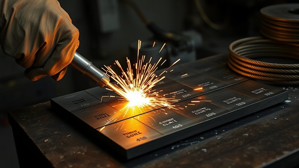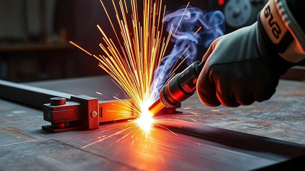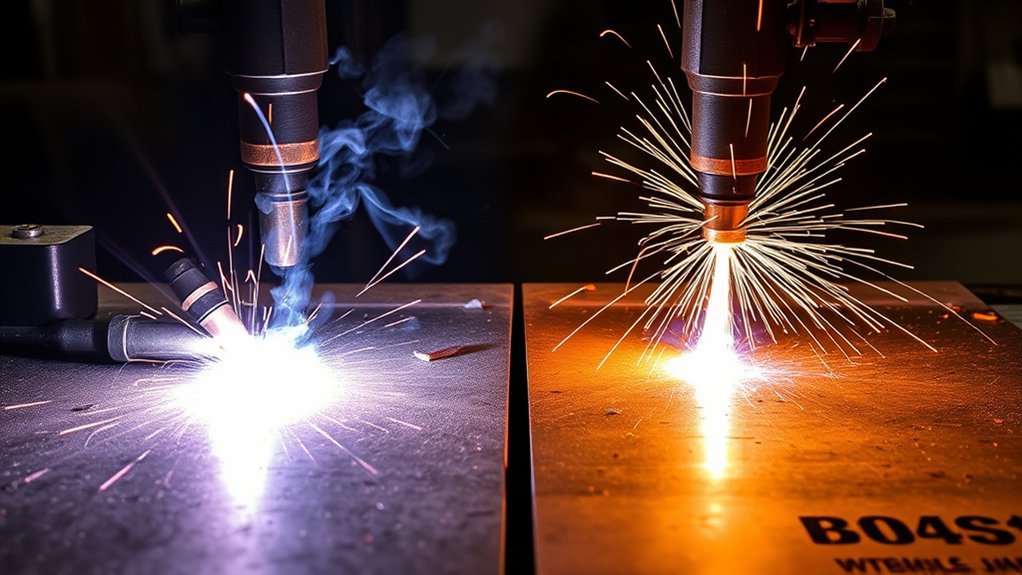
The right plasma cutter setting is not simply “40 amps for thin metal and 60 amps for thick metal.” Plate thickness matters, but so do the torch, consumable rating, cut speed, cut height, air quality, input power, duty cycle, and the finish you need. Use the figures below as examples, then confirm every production setting with the cut chart for your exact machine and a test cut on matching scrap.
Quick Answer
Use 40A-class cutting for thin to medium plate, detail work, and slower hand-guided cuts. Use 60A-class cutting when thicker plate or production speed calls for it. Neither setting is automatically cleaner or cooler: match the amperage-rated consumables, follow the machine’s cut chart, and tune travel speed and torch height with a scrap test.
Key Takeaways
- Choose 40A-class cutting when the manufacturer charts it for the material and you value control, fine features, and a smaller matched nozzle.
- Choose 60A-class cutting for thicker plate or higher throughput when the torch, consumables, circuit, compressor, and duty cycle support it.
- Do not assume lower amperage always means less distortion or that higher amperage always means a cleaner edge. Heat input depends heavily on travel speed and dwell time.
- Kerf, dross, and bevel depend on the complete process: nozzle or cartridge, current, speed, height, material, gas flow, and consumable condition.
- Treat clean-cut, pierce, and severance ratings as different limits. A machine that can sever a thickness may not make a production-quality cut in it.
At a Glance
| Time Required | 5–10 minutes to inspect the setup and make test cuts before production |
| Difficulty | Moderate; the controls are simple, but edge quality depends on speed, height, air, and technique |
| Tools Needed | Plasma cutter, amperage-matched consumables, clean dry air, work clamp, PPE, matching scrap, and a tape measure or calipers |
| Cost | Usually no added cost beyond consumables, air treatment, electrical capacity, and normal hot-work safety gear |
Warning: Plasma cutting creates intense arc radiation, hot slag, fire and electrical hazards, high noise, and metal fumes. Wear eye and face protection with the lens shade specified by the equipment manual and applicable rules, protect exposed skin, remove combustibles, provide ventilation, and never cut a closed container or an unknown coated surface.
Material Thickness and Recommended Amperage
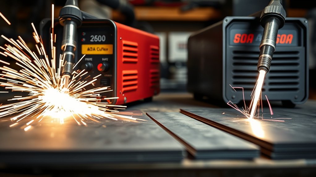
Match amperage to the material, thickness, consumable set, and cut-quality target. A 40A-class process is commonly used for sheet metal, 1/8-inch steel, 3/16-inch steel, and some 1/4-inch work. A 60A-class process is commonly used for faster 1/4-inch cutting and for thicker mild steel such as 3/8 inch and 1/2 inch. Those are categories, not universal settings.
Machine labels also create confusion. A cutter advertised as “40A” may have a different torch, arc voltage, air requirement, and recommended capacity than another 40A unit. Likewise, Hypertherm’s 45A and 65A chart data can show the difference between two amp classes, but it does not become a cut chart for an unrelated 40A or 60A machine.
Do not rely on a fixed shortcut such as “10 amps per 1/8 inch.” It ignores torch design, nozzle size, material type, line voltage, air flow, and duty cycle. Start with the manufacturer’s chart for the exact power supply, torch, and consumables. Hypertherm’s Powermax45/65/85/105 SYNC Cut Charts Guide, for example, separates amperage, material, cut height, pierce height, speed, arc voltage, kerf width, and gas flow.
Use the lowest charted process that gives the quality and productivity you need—not the lowest current the knob can produce and not the highest current the machine can deliver.
The table below is a practical starting guide for mild steel. “40A/45A-class” and “60A/65A-class” describe general process ranges; your machine’s chart remains the controlling source.
| Mild steel thickness | 40A/45A-class starting point | 60A/65A-class starting point | Practical choice |
|---|---|---|---|
| 1/8 in | Usually the better standard or fine-feature range | Often not charted with standard 65A consumables | Favor the lower charted process to limit top-edge rounding and make hand control easier |
| 3/16 in | Good for accurate hand cuts and fine features | Faster when specifically charted | Choose control or throughput based on the chart and part geometry |
| 1/4 in | Common clean-cut range at moderate speed | Common production range at much higher speed | Both can work; compare kerf, dross, speed, and distortion on scrap |
| 3/8 in | Possible on many machines, but slower | Usually gives more speed headroom | 60A-class is usually the stronger production choice |
| 1/2 in | Slow; piercing or edge-start limits may apply | Better suited to repeat work when charted | Use the machine’s recommended-cut and pierce ratings, not its severance claim |
Clean Cut, Pierce, and Severance Ratings Are Different
A recommended or clean-cut rating describes a thickness the machine can cut at a useful speed and finish. A pierce rating is the thickness the torch can pierce from the face of the plate under the stated conditions. A severance rating is the maximum thickness it can separate, usually slowly and with more bevel and dross. For example, the current Powermax65 SYNC specifications list separate recommended, pierce, and hand-severance capacities rather than treating them as one number.
When the plate is near the machine’s pierce limit, an edge start may protect the consumables and complete the cut more reliably. Never substitute an edge start for a charted pierce when a CNC program or finished part requires a true internal pierce.
Material type matters too. Stainless steel and aluminum do not behave like mild steel at the same thickness. Their charted speeds, kerf widths, gas requirements, and edge appearance can differ. Start with the chart for the exact material, then make a short test cut before committing to the part.
Cutting Speed Tradeoffs at 40A vs 60A
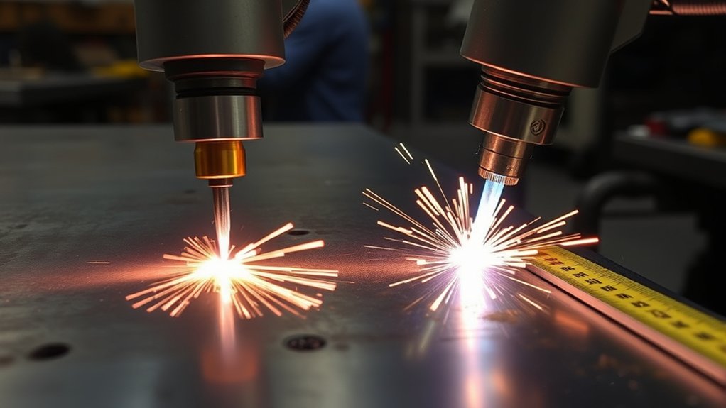
Cutting speed is where the two amp classes feel most different. A lower-current process often gives a hand operator more time to steer through curves and small features. A higher-current process can move much faster on plate that is thick enough to use the extra arc energy. It also demands steadier motion, correct torch height, and enough air flow to stay inside the charted process window.
Lower amperage does not guarantee lower total heat input. If a 40A cut travels much more slowly than a 60A cut, the arc can spend longer over each inch of metal. Distortion depends on current, arc voltage, travel speed, path sequence, part geometry, and how much heat the workpiece can absorb. The right comparison is the finished test cut, not amperage by itself.
The official June 2024 Hypertherm SYNC guide provides a useful example. Its mild-steel charts show 45A and 65A best-quality-to-highest-production speed ranges as follows. These are manufacturer-specific mechanized reference values, not settings to copy into another machine.
| Mild steel | 45A chart range | 65A chart range | What it shows |
|---|---|---|---|
| 1/4 in (6 mm) | 46–74 ipm | 93–117 ipm | Both processes are charted, but 65A offers much more throughput |
| 3/8 in (10 mm) | 33–38 ipm | 44–64 ipm | 65A expands the usable speed window |
| 1/2 in (12 mm) | 18–24 ipm | 30–40 ipm | 65A is better matched to repeat production cutting |
If the torch outruns the cut, the arc trails backward, the kerf may fail to open fully at the bottom, and a hard bead of high-speed dross can remain. Slow down in small steps, lower excessive standoff, inspect the nozzle, or move to a charted higher-current process. If the cut is too slow, you may see easily removed low-speed dross and excess heat at corners; increase speed, raise the standoff only within the charted range, or use a lower-current matched process.
Pro Tip: Before cutting the finished part, make several 3-inch lines on scrap from the same material. Change only one variable at a time—usually speed first—then compare dross, bevel, top-edge shape, lag lines, and whether the arc exits cleanly through the bottom.
Cut Quality, Kerf, and Bevel Considerations
Cut quality depends on the full setup, not amperage alone. Hypertherm’s cut-quality troubleshooting guidance points to process selection, travel direction, speed, torch height, gas flow, consumable condition, and machine condition. A 60A process can be cleaner on thick plate, yet too aggressive for thin stock if the process is not charted or the operator cannot maintain the required speed.
Kerf is not automatically narrower at higher amperage. A correctly matched 40A or 45A nozzle can produce a tight kerf on thin material. A 60A or 65A process often uses a larger orifice and may produce a wider kerf, although speed and height can shift the result. For fitted parts, measure the kerf from a test coupon and apply that value to the layout or CNC kerf compensation.
Bevel can come from torch height, travel speed, worn consumables, incorrect torch angle, gas-flow problems, or the normal swirl of the plasma jet. An out-of-round nozzle or damaged cartridge can make a sound amperage setting produce a poor edge.
| Cut defect | Likely cause | Adjustment to try |
|---|---|---|
| Easily removed, bubbly bottom dross | Travel too slow, excessive current for the process, or standoff too low | Increase speed in small steps; confirm current, nozzle rating, and cut height |
| Hard, narrow bottom dross or incomplete cut | Travel too fast, current too low, standoff too high, or worn nozzle | Reduce speed, check height and consumables, or use a charted higher-current process |
| Top spatter | Worn nozzle, excessive speed, or high standoff | Inspect the nozzle, reduce speed, and reset cut height to the chart |
| Rounded or washed top edge | Process too energetic for the thin material, travel too slow, or height incorrect | Use the lower charted process or increase speed while staying inside the chart |
| Strong or uneven bevel | Torch not square, wrong travel direction, worn nozzle, wrong speed, or incorrect height | Square the torch, confirm direction, reset height and speed, and replace damaged consumables |
| Arc stops before the cut finishes | Poor work-lead contact, weak air delivery, duty-cycle shutdown, or inadequate input power | Clean the clamp point, verify dynamic air flow, allow cooling, and check the circuit and extension-lead limits |
Cut Direction and the “Good Side”
Most conventional torches swirl the plasma gas clockwise. With standard consumables, the squarest edge is generally on the right side of the kerf as the torch moves forward. That usually means traveling clockwise around an outside contour and counterclockwise around an internal hole so the better edge stays on the finished part. Confirm the rule for your torch and process with the manual and a test cut.
Setup, Tip Selection, and Standoff for Best Results
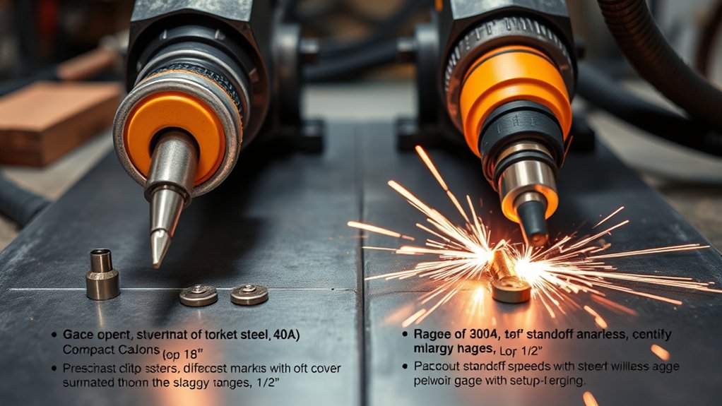
Start with the work lead. Attach it to bright, bare metal or a clean cutting table with a dependable electrical path to the workpiece. Paint, heavy rust, mill scale, loose slats, and a distant clamp point can interfere with arc transfer and create rough starts or interruptions.
Next, match the consumables to the current and process. Do not run a 60A nozzle at 40A merely because it fits, and do not run a 40A nozzle at 60A to force a narrow kerf. The nozzle or cartridge is designed for a specific energy density and gas flow. A mismatch can destabilize the arc, overheat parts, widen the cut, shorten life, or damage the torch.
Use the cut height listed in the chart. Many shielded hand torches permit drag cutting with the correct drag shield. Mechanized systems normally use a fixed cut height or torch-height control and a higher initial pierce height. Do not scrape an exposed nozzle across the plate unless the manual specifically permits it.
- Identify the exact process. Confirm material, thickness, hand or mechanized torch, drag or standoff method, and desired cut quality.
- Install matched consumables. Verify the nozzle, electrode, shield, swirl ring, retaining cap, or cartridge part numbers.
- Set current and air from the chart. Use the specified pressure or flow test procedure; static gauge pressure alone may not show whether the compressor can maintain flow while cutting.
- Connect the work lead. Clamp to clean metal close enough to provide a reliable path without putting the lead in the slag stream.
- Square and position the torch. Set drag contact or standoff as the manual requires.
- Make a short test cut. Use scrap of the same alloy, thickness, and surface condition.
- Tune one variable at a time. Adjust speed first unless the observed defect points clearly to height, air, current, or consumables.
- Inspect the result. Check dross type, bevel, top-edge rounding, lag lines, kerf width, and complete separation before cutting the final part.
Note: CNC settings can differ from hand-cut settings at the same amperage. A CNC table controls speed, lead-ins, pierce delay, kerf compensation, and torch height more consistently, so it can often run near published mechanized chart speeds that are unrealistic for freehand cutting.
Products Worth Considering

Package Include: 10 Shield Cups, 50 Nozzles, 20 Swirl Baffle, and 30 Electrodes.

[Achieve Precise Cuts] PT31 Plasma Cutting Consumables – Your Essential Tool for Efficient Cutting! Whether you're working with sheet metal, steel, or any other material, superior cutting performance ensure clean, accurate, and smooth cuts.

High-Quality Material:Made of high quality material to ensure a longer lifespan and superior performance.
Safety, Duty Cycle, and Power/Air Requirements
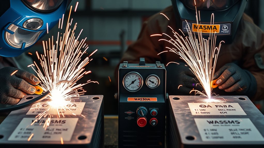
Safe, repeatable cutting at 40A or 60A depends on duty cycle, input power, air delivery, and shop controls. A 60A process usually demands more from the power supply and branch circuit than a 40A process. It may also have a different duty-cycle rating. Read the nameplate and manual rather than assuming a machine can stay at maximum output for an entire long cut.
Duty cycle is the share of a stated test period—commonly 10 minutes—that the power source can operate at a specified output and ambient temperature before it must cool. It is tied to a particular current and test condition. A machine rated for six minutes at one output is not automatically rated for six minutes at every line voltage, temperature, or installation.
Air supply is just as important as current. Use clean, dry compressed air and follow the machine’s pressure and flow requirement. A regulator may show adequate pressure before the arc starts while the pressure collapses during the cut because the compressor, hose, filter, or fittings cannot sustain the required flow. Drain the receiver, use suitable filtration, and add drying equipment when moisture reaches the torch.
| Parameter | 40A-class | 60A-class |
|---|---|---|
| Typical use | Thin to medium plate, detailed hand work, lower-current consumables | Thicker plate and faster production cutting |
| Duty cycle | May be higher than the machine’s maximum-output duty cycle, but verify the chart | Often closer to maximum output; cooling limits matter more on long cuts |
| Air supply | Clean, dry air at the manual-specified dynamic pressure and flow | Clean, dry air with enough sustained compressor capacity for the charted process |
| Input power | May run on a smaller circuit on some machines; follow nameplate requirements | Usually needs greater input capacity; avoid undersized cords and adapters |
| Quality focus | Avoid dwelling in corners and keep speed steady | Maintain the faster charted speed, height, and air flow |
Plasma cutting can produce metal fumes and gases whose hazards depend on the base metal, coatings, contamination, and work environment. OSHA lists metal fumes and ultraviolet radiation among cutting hazards, along with burns, eye injury, and electrical shock. Its welding, cutting, and brazing hazard guidance should be treated as a starting point, not a substitute for a site-specific hazard assessment.
The American Welding Society’s updated Ventilation for Welding and Cutting fact sheet advises keeping your head out of the plume, capturing fumes near the source, and using an appropriate NIOSH-approved respirator when ventilation is not adequate or practical. Do not cut galvanized, painted, plated, stainless, or unknown metal until you identify the coating and choose suitable controls. Confined-space cutting requires a dedicated procedure, atmospheric testing, ventilation, and rescue planning.
Noise must be assessed rather than guessed from amperage. In U.S. general industry, OSHA’s occupational noise standard uses 85 dBA as the 8-hour time-weighted-average action level for a hearing conservation program and 90 dBA as the 8-hour permissible exposure level in Table G-16. Wear suitable hearing protection whenever measurements, the equipment manual, or shop conditions show it is needed.
How to Choose Between 40A and 60A
Use this decision process when both amp classes appear capable of cutting the plate:
- Check the exact cut chart. Confirm that the material and thickness are listed for the torch and consumable set you plan to use.
- Separate cut capacity from pierce capacity. A chart may allow an edge start at a thickness it does not permit you to pierce.
- Choose the process for the part. Lower-current consumables often suit fine shapes, small holes, and hand control. Higher-current consumables favor straight production cuts and thicker plate.
- Verify the consumables. Match the nozzle or cartridge to the amperage and cutting mode; do not mix ratings to chase a smaller kerf.
- Check duty cycle and input power. Confirm that the circuit, plug, leads, and power source can support the planned cut length.
- Check air under flow. Confirm pressure and flow while the machine is in its air-test or cutting condition, not only while idle.
- Make test cuts at chart speed. Compare dross, bevel, kerf, top edge, and distortion.
- Choose the least total rework. The winning setting is the one that produces a complete, repeatable cut with acceptable speed and the least grinding—not simply the one with the highest amperage.
Pro Tip: Mark each test coupon with amperage, speed, consumable type, cut height, and air setting. A small labeled sample library becomes a more useful shop reference than a generic online chart because it reflects your machine, compressor, material, and technique.
Products Worth Considering

PACKAGE INCLUDED: 5 Pcs Cup-15 Pcs Electrodes-10 Pcs Ring-30 Pcs Tip(Standard)

Fit for : AG-60 AG-60P SG-55 WSD-60 Plasma cutter torch head

⚡【Precision Compatibility】 Exact fit for YESWELDER CUT 55DS Pro & 65DS (2019-2024 models). Replaces OEM# IPT40-55DS/65DS.
Frequently Asked Questions
How do 40A vs 60A affect consumable life and operating cost?
Amperage alone does not predict consumable life. Life depends on using the correct rated parts, pierce count, air quality, torch height, starts and stops, duty cycle, and whether the arc is extinguished correctly. A 60A process may consume more power while cutting, but its higher speed can reduce arc-on time and grinding on thicker plate. Compare total cost per finished part.
Can CNC table settings differ from hand cutting at the same amperage?
Yes. CNC cutting uses steadier travel speed, controlled pierce height, cut height, pierce delay, lead-ins, lead-outs, and kerf compensation. A hand operator may need a slower or more forgiving process, and mechanized chart speeds should not be copied blindly into freehand work.
What edge preparation is needed for welding after 40A vs 60A cuts?
Remove dross, oxide, paint, oil, coatings, and rough or hardened areas that could interfere with the weld. The amount of grinding depends more on cut quality and the welding procedure than on amperage alone. Structural work must follow the applicable welding procedure, code, and inspection requirements.
How do ambient temperature and humidity affect cut consistency?
Humidity can add moisture to compressed air, while high shop temperature can reduce cooling margin and duty cycle. Cold conditions can also change compressor behavior and condensation patterns. Keep the air dry, drain the receiver, maintain filters, and repeat a test cut when shop conditions change noticeably.
Are there noise and fume differences between 40A and 60A cuts?
There can be, but the direction and size of the difference depend on material, coating, speed, arc-on time, air flow, enclosure, and ventilation. Do not select PPE or ventilation from amperage alone. Measure noise where needed, identify the metal and coating, and control the plume at the source.
Is 60A always better for 1/4-inch steel?
No. A 60A-class process can cut 1/4-inch steel much faster when charted, but a 40A or 45A process may give easier hand control, a smaller matched kerf, or better fine-feature results. Compare both charted processes on scrap and choose the one that meets the part tolerance with the least rework.
Can a 40A plasma cutter cut 1/2-inch steel?
Some 40A or 45A-class machines can cut or sever 1/2-inch mild steel slowly, and some charts may require an edge start. That does not make every 40A cutter suitable for clean repeat production at that thickness. Check the exact recommended-cut, pierce, and severance ratings before you begin.
Can I use a 60A nozzle while cutting at 40A?
Only when the manufacturer specifically charts that combination. A larger nozzle run below its intended current may produce poor energy density or unstable cut quality. Use the nozzle, cartridge, shield, and other parts listed for the selected process.
What does a 60% duty cycle mean on a plasma cutter?
At the stated output and test conditions, 60% duty cycle commonly means six minutes of cutting in a 10-minute period followed by four minutes of cooling. Verify the manual because duty cycle changes with output current, input voltage, ambient temperature, and the standard used for the rating.
Conclusion
Choose between 40A and 60A by using the exact cut chart, not a thickness shortcut. A 40A-class process often suits thinner material, detailed shapes, and hand control. A 60A-class process usually earns its place on thicker plate and production work where its higher charted speed reduces cycle time. For 1/4-inch mild steel, both classes may work; 3/8 inch often favors 60A-class throughput; and 1/2 inch requires careful attention to recommended-cut, pierce, edge-start, and duty-cycle limits. Match the consumables, verify air and input power, make labeled test cuts, and choose the setting that delivers the least dross, acceptable bevel, and repeatable dimensions.
Sources
- Hypertherm Powermax45/65/85/105 SYNC Cut Charts Guide, Revision 4 — supports the 45A and 65A mild-steel speeds, kerf examples, cut and pierce heights, and gas-flow data.
- Hypertherm Cut Quality Troubleshooting — supports diagnosis of dross, bevel, kerf, travel direction, speed, height, and consumable problems.
- Hypertherm Powermax65 SYNC Specifications — illustrates the difference between recommended cutting, piercing, and severance capacity.
- OSHA Welding, Cutting, and Brazing Hazards and Solutions — supports the fume, radiation, burn, eye-injury, and electrical-hazard guidance.
- OSHA 29 CFR 1910.95 Occupational Noise Exposure — supports the 85 dBA action level and 90 dBA permissible exposure context for U.S. general industry.
- American Welding Society Fact Sheet No. 36: Ventilation for Welding and Cutting — supports source capture, breathing-zone control, exposure evaluation, and respirator guidance.