A 30 amp plasma cutter can make fast, accurate cuts on sheet metal and plate, but “30 amp” does not give you one universal pressure, tip, speed, or thickness limit. The right setup depends on the exact cutter, input voltage, torch, consumables, air requirement, metal, and cut-quality goal. Use this guide to understand the variables, then confirm every final setting in your machine’s cut chart.
Quick Answer
A 30 amp plasma cutter does not have one universal pressure, tip, or speed. Use the cut chart for your exact model, input voltage, consumables, and metal. Current 30 A machines commonly rate clean mild-steel cuts around 3/8 inch, while 1/2–5/8 inch is slower or severance-only territory.
Key Takeaways
- Treat the operator manual and cut chart as the final authority. Air requirements, consumables, speed, capacity, and duty cycle vary by model.
- Do not confuse 30 A cutting output with the amperage drawn from the wall. Use the required branch circuit, plug, and input voltage shown on the nameplate.
- A 240 V supply often provides the machine’s full output. Some dual-voltage cutters reduce maximum output when connected to 120 V.
- Do not double the amperage for aluminum. Keep the current within the cutter and nozzle rating, then follow the aluminum cut chart.
- Change one variable at a time during troubleshooting: speed first, then standoff, current, air delivery, consumables, and work-lead contact.
At a Glance
| Time Required | About 10–20 minutes for inspection, setup, and a scrap test; cutting time varies by the job |
| Difficulty | Beginner to intermediate |
| Tools Needed | 30 A plasma cutter, approved consumables, required air supply, work clamp, scrap metal, straightedge or guide, and complete PPE |
| Cost | No added cost beyond compatible consumables, dry-air equipment, electrical service, and PPE already required by the machine |
How 30 Amp Plasma Cutter Ratings Work
The 30 A label describes the machine’s maximum cutting-output current. It does not mean the cutter must be connected to a 30 A wall receptacle, and it does not prove that every 30 A machine has the same cut capacity.
Two machines with the same maximum output can use different torches, power electronics, consumables, air regulators, and input circuits. Those differences affect speed, edge quality, pierce capacity, duty cycle, and the maximum thickness the machine can sever.
Output Amperage Versus Input Power
Always size the electrical supply from the machine’s nameplate and electrical-service table. Do not size the circuit from the “30 A” cutting-output number.
Dual-voltage cutters may also produce less output on 120 V. For example, the Hypertherm Powermax30 XP specifications list a maximum recommended output of 25 A on 120 V, compared with the full 30 A range available under the machine’s specified 240 V setup.
Note: Reduced voltage can mean lower output, slower travel, less pierce capacity, or a shorter duty cycle. Confirm the machine’s 120 V and 240 V ratings separately.
Air Pressure and Flow Are Model-Specific
There is no universal 55–60 psi setting for all 30 A plasma cutters. Check both the required flow rate, stated in SCFM or liters per minute, and the required inlet pressure.
- The Powermax30 XP specifies clean, dry, oil-free air or nitrogen at 4 SCFM and 80 psi.
- The Miller Spectrum 375 X-TREME specifies clean, moisture-free, oil-free air at 5 SCFM and an inlet range of 90–120 psi in its official owner’s manual.
- Some portable cutters use an internal compressor and do not need an external air line.
Measure or verify pressure while air is flowing. A compressor can show adequate static pressure and still fall below the required flow once the torch opens.
30 Amp Plasma Cutter Thickness and Capacity
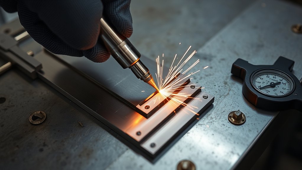
A 30 A cutter is well suited to sheet metal, brackets, body panels, HVAC work, light fabrication, and moderate plate. Its exact limit depends on the model and on what the manufacturer means by “capacity.”
| Capacity term | What it means | Practical expectation |
|---|---|---|
| Quality or recommended cut | A thickness the machine can cut at a useful speed with acceptable edge quality | Commonly around 3/8 inch mild steel on current professional 30 A examples |
| Slow or maximum cut | A thicker cut made more slowly, often with more bevel and cleanup | Approximately 1/2 inch on the verified examples |
| Severance | The greatest thickness the arc can separate, not a promise of production-quality edges | Up to about 5/8 inch on the verified examples, at very low speed |
| Pierce capacity | The thickness through which the torch may safely start away from an edge | Often lower than edge-start capacity; check the torch manual |
For repeated work, choose a machine whose recommended capacity is comfortably above the material you cut most often. Running at the upper limit slows production, increases heat input, and can shorten consumable life.
Products Worth Considering
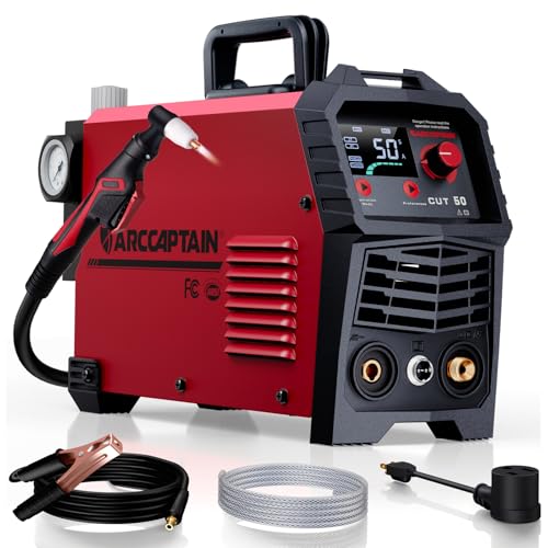
【Powerful Cutting Ability】Switch effortlessly between 110V and 220V for home or workshop use. Achieve professional 1/2" clean cuts on steel, aluminum, and copper with advanced LGBT technology. Perfect for DIY projects and heavy-duty tasks. Recommended maximum cutting thickness: 12mm @ 35A / 110V / 55 PSl; 18mm @ 50A / 220V / 75 PSI. Note: Requires compressed air (compressor sold separately).

IGBT Inverter Power:Powered by advanced IGBT inverter technology, this 30A plasma cutter delivers consistent output for smooth, precise cutting on carbon steel, stainless steel, aluminum, and even mesh metals. Under 110V, it achieves clean cuts up to 8mm (5/16") with a maximum cutting capacity of 12mm (15/32") – suitable for most home garage repairs, automotive panels, and small workpiece fabrication.Note: Requires compressed air (compressor sold separately).

Incorporates advanced IGBT inverter technology with an excellent Arc stability. The torch design provides a sure and comfortable grip made with heat and impact resistant material. 100~250V wide voltage, 50~60Hz, almost all of the voltage and frequency can be used.
Mild Steel, Stainless Steel, and Aluminum
Air plasma can cut any electrically conductive metal, including mild steel, stainless steel, aluminum, brass, and copper. The same thickness will not always cut at the same speed or produce the same edge finish.
- Mild steel: Manufacturer charts usually provide the most complete speed data and are the best starting point.
- Stainless steel: Expect different edge color, dross behavior, and speed. Stainless fumes may also contain hazardous chromium compounds, so effective source ventilation is important.
- Aluminum: Do not double the amperage. Keep the output within the machine and nozzle rating and follow the manufacturer’s aluminum chart. Miller notes that aluminum and stainless speeds may be up to 20% below its mild-steel reference speeds at the same thickness.
Pro Tip: Write the metal, thickness, input voltage, current, consumable set, air reading, and successful travel speed on a shop card. A short record is more useful than trying to remember a “universal” setting.
Amperage, Consumable, and Air Settings
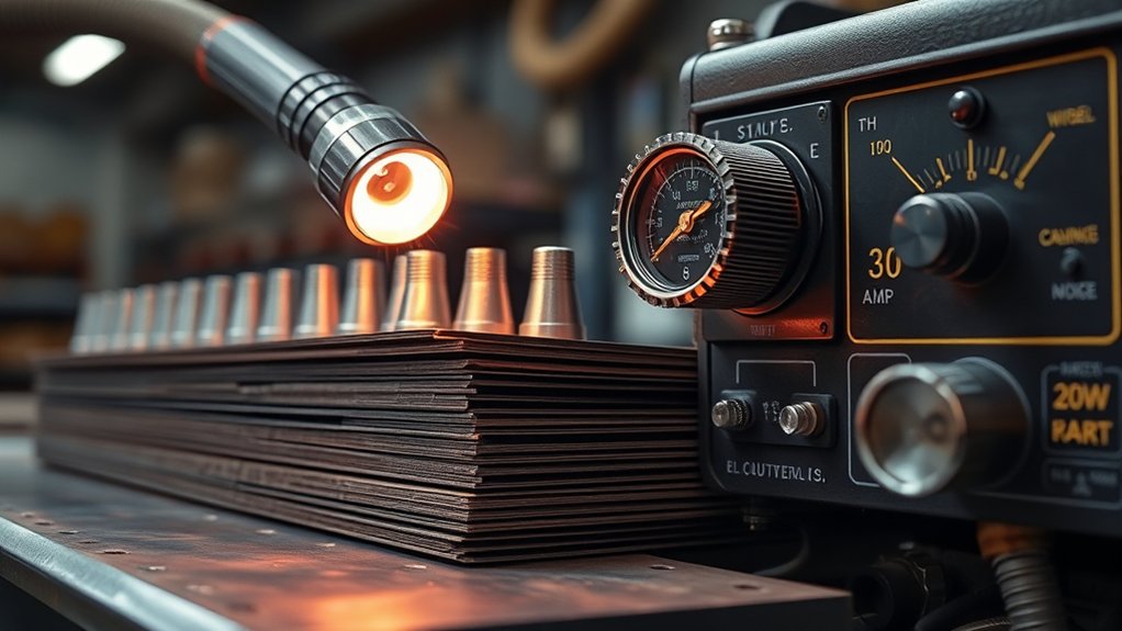
Start with the cut chart for the exact torch and consumable set. A nozzle or tip is designed for a stated current range. Running more current than it is rated to carry can enlarge or distort the orifice, widen the kerf, and shorten electrode life.
| Setting | Correct method | Common mistake |
|---|---|---|
| Current | Use the charted amperage and a consumable rated for that current | Running a low-amperage nozzle at the machine’s full output |
| Consumables | Install the approved electrode, nozzle, swirl ring, retaining cap, and shield as a matched set | Mixing parts from different amperage ranges or torch families |
| Air | Meet the specified SCFM and flowing inlet pressure with clean, dry, oil-free air | Setting a generic pressure or checking only static pressure |
| Standoff | Drag the shield only if the consumables are designed for drag cutting; otherwise use the manual’s standoff | Dragging an exposed nozzle directly on the work |
| Torch angle | Hold the torch close to 90 degrees while cutting | Leaning the torch 10–15 degrees through the cut |
| Work lead | Attach it to clean, bare metal close to the cut | Clamping over paint, rust, scale, or a loose joint |
Fine-feature or fine-cut consumables can reduce kerf and heat input on thin material, but only use them when they are approved for your torch. “FineCut” is not a generic tip specification shared by every brand.
Products Worth Considering
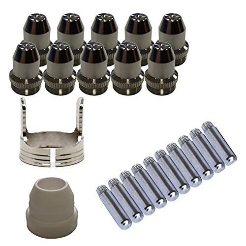
Only Compatible with BROWN Color Lotos LTP5800D , LTP5000D, LTPDC2000D.

Fit for : AG-60 AG-60P SG-55 WSD-60 Plasma cutter torch head

Can only be used for BROWN Color Lotos LT5000D and BROWN Color Lotos CT520D
Cutting Speed by Metal Type and Thickness
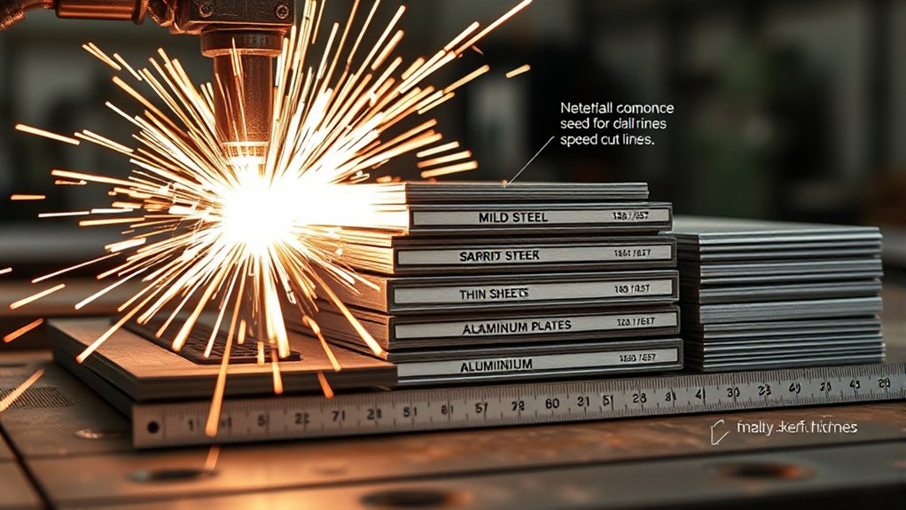
Cutting speed changes sharply with thickness. A single range such as 24–38 IPM cannot cover both thin sheet and the upper limit of a 30 A cutter.
The following figures are from the official Miller Spectrum 375 X-TREME chart at 30 A. They are useful reference points, not universal settings for every 30 A machine.
| Mild-steel thickness | Miller reference speed at 30 A | Cut class |
|---|---|---|
| 12 gauge | 105 IPM | Fast sheet-metal cutting |
| 1/8 inch | 98 IPM | Fast quality cut |
| 3/16 inch | 63 IPM | Quality cut |
| 1/4 inch | 36 IPM | Quality cut |
| 3/8 inch | 18 IPM | Rated edge-start cut for this model |
| 1/2 inch | 10 IPM | Slow maximum-range cutting |
| 5/8 inch | 6 IPM | Severance territory |
On one verified 30 A chart, the recommended speed falls from 98 IPM at 1/8 inch to 18 IPM at 3/8 inch. Thickness changes the correct speed far more than a single generic range suggests.
The Powermax30 XP provides another useful comparison. Its current specifications list 20 IPM at 3/8 inch, 10 IPM at 1/2 inch, and 5 IPM for 5/8-inch severance. On 120 V at a maximum recommended 25 A, Hypertherm lists lower speeds of 19 IPM at 1/4 inch, 8 IPM at 3/8 inch, and 3 IPM at 1/2 inch.
Begin with your charted speed and make a short scrap cut. Watch the sparks exiting below the plate and inspect the bottom edge before changing the setting.
Kerf Width, Edge Quality, and Dross
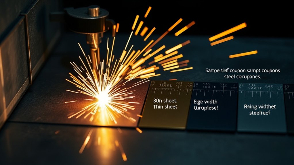
The final kerf width is not simply the nozzle-orifice diameter. It changes with current, consumable design, metal, thickness, speed, standoff, torch angle, and consumable wear.
For layout work, make a test cut and measure the actual kerf produced by your setup. This is especially important for fitted parts, slots, decorative work, and CNC compensation.
How to Identify Dross
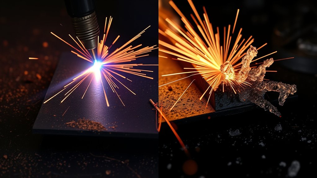
- Low-speed dross: Heavy, rounded, or bubbly material along the bottom edge. Increase speed in small steps. Excess current or an overly short standoff can create a similar heat-heavy condition.
- High-speed dross: A thin, hard bead that is difficult to remove. Reduce speed in small steps and check for excessive standoff, low current, or a worn nozzle.
- Top spatter: Metal deposited on the top surface. Check the nozzle, speed, standoff, and pierce height or technique.
- Incomplete cut: Sparks spray upward or the arc fails to pass through. Reduce speed, verify current and input power, check air delivery and consumables, and confirm that the material is within the machine’s capacity.
Bevel can come from a torch that is not square, excessive standoff, a damaged nozzle, incorrect travel direction on mechanized work, or normal plasma-arc angularity. Inspect the consumables before trying to correct every bevel problem with speed.
Setup for Thin Sheet Metal to Minimize Warping
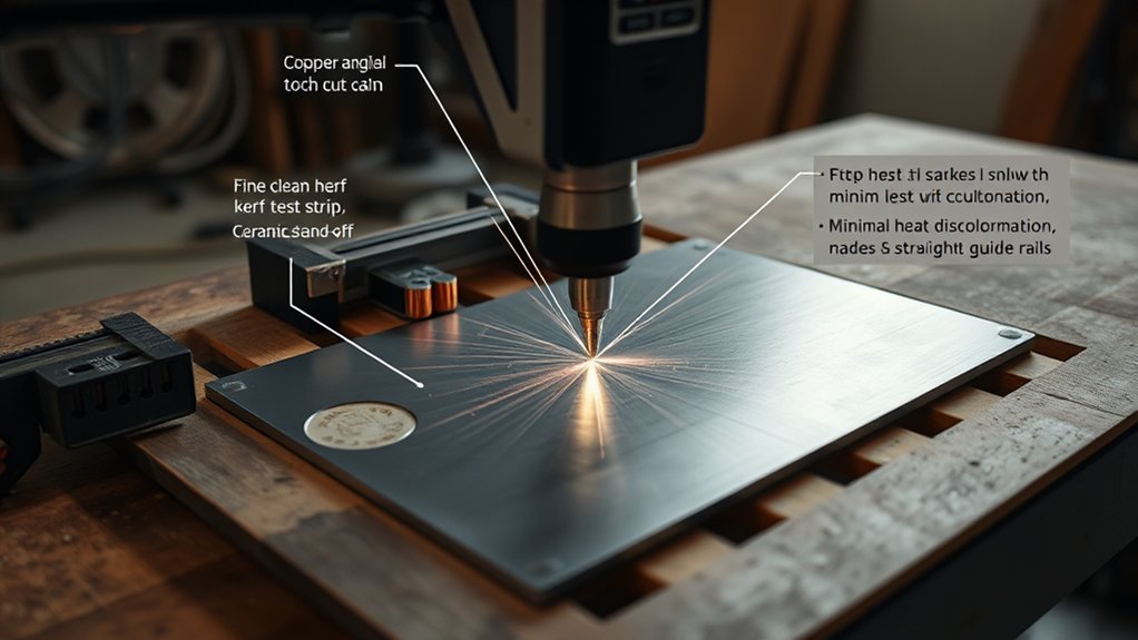
Thin sheet heats and moves quickly. The goal is to support the panel, use the lowest appropriate heat input, and keep the torch moving at the charted speed.
Secure Fixturing Methods
- Support the sheet on a stable, nonflammable cutting surface that allows sparks and molten metal to fall clear.
- Use low-profile edge clamps and add restraint where the sheet can lift or vibrate. Clamp spacing of roughly 150–300 mm can be a starting point on small panels, but adjust it to the panel’s stiffness and shape.
- Keep clamps, weights, and crossbars outside the torch path. Do not place a conductive backing bar directly beneath the kerf unless an approved procedure calls for it, because the plasma arc can transfer to the backing.
- Use nonmagnetic clamps or weights where practical. Strong magnets close to the cut can disturb the arc on some work.
- Check that the sheet is flat before cutting. Uneven height changes standoff and can widen the kerf or cause incomplete cuts.
Control Speed and Heat Input
Use the charted current for the thin material rather than automatically running at 30 A. If your torch offers an approved fine-feature consumable, it may produce a narrower kerf and smaller heat-affected zone.
Run a straight test cut. Increase speed if you see heavy, easy-to-remove low-speed dross. Decrease speed if the arc trails badly, sparks return upward, or a thin, hard high-speed bead forms.
For long cuts, alternate the cutting direction or sequence separate areas so heat does not build in one zone. Avoid pausing in corners. A guide, template, or steady straightedge helps maintain speed without wandering.
Piercing Thin Sheet
Edge-starting reduces molten-metal blowback and consumable wear. When an interior pierce is required and the thickness is within the machine’s pierce rating, follow the torch manual.
A common handheld method is to begin with the torch at approximately 45 degrees, start the arc, and rotate to 90 degrees as the arc penetrates. This directs the first burst of molten metal away from the nozzle. Do not use this technique where the manufacturer specifies a different process.
Techniques for Clean Cuts on 1/8- to 1/4-Inch Material
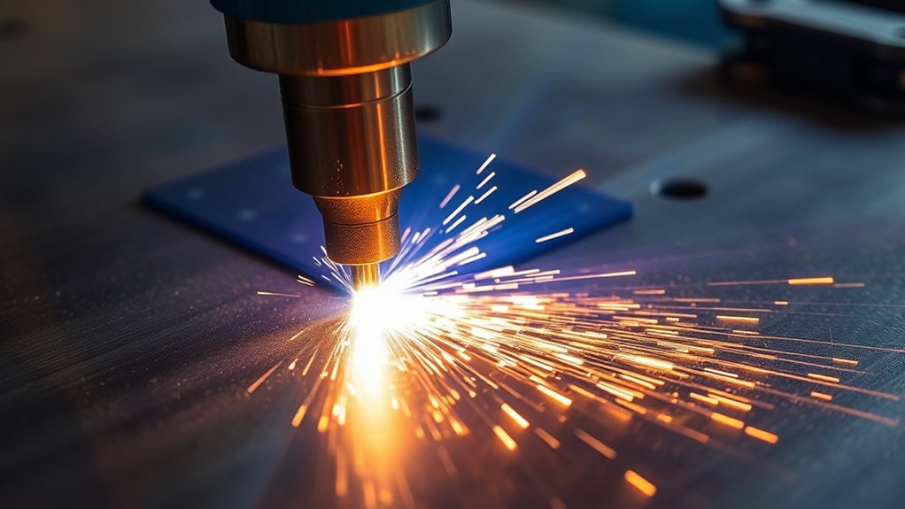
Material from 1/8 to 1/4 inch is comfortable working territory for many 30 A cutters. The following process gives you a repeatable starting point without assuming that every machine shares the same pressure or speed.
- Identify the metal and thickness. Remove loose scale, oil, paint, or coatings near the cut. Review the safety data for unknown or coated material.
- Confirm input power. Verify that the supply voltage, receptacle, branch circuit, and plug match the nameplate and manual.
- Install approved consumables. Disconnect input power before opening or servicing the torch. Check the nozzle for an enlarged or oval opening and inspect the electrode for excessive wear.
- Prepare the air supply. Meet the machine’s required flowing pressure and SCFM. Drain the compressor receiver and filter, and remove water or oil contamination.
- Attach the work clamp. Use clean, bare metal close to the cutting area.
- Secure the work. Clamp the plate so it cannot shift, vibrate, or fall when the cut finishes.
- Make a scrap test. Start at the charted current and speed. Use a drag shield on the surface only if it is designed for drag cutting; otherwise maintain the specified standoff.
- Hold the torch square. Keep the torch close to 90 degrees during the cut and move smoothly. Pulling the torch is often easier for handheld work.
- Inspect the sparks and edge. Sparks should pass through the plate. Identify low-speed or high-speed dross before changing travel speed.
- Adjust one variable at a time. Record the final setting that produces full penetration, manageable dross, and acceptable bevel.
| Visual cue | Likely meaning | First correction |
|---|---|---|
| Sparks pass through and trail slightly | Speed is close to correct | Continue and inspect the finished edge |
| Sparks flare upward | Too fast, too little current, poor air delivery, or weak work connection | Slow slightly and verify the setup |
| Heavy, rounded bottom dross | Low-speed dross | Increase speed in small steps |
| Thin, hard bottom bead | High-speed dross | Reduce speed and check standoff |
| Uneven bevel on changing sides | Torch angle, nozzle wear, or height problem | Square the torch and inspect consumables |
Safety and Duty Cycle at 30 Amps
Warning: Never cut a sealed, pressurized, fuel-contaminated, or unknown container. Remove combustible material, provide effective ventilation, protect people from arc radiation and sparks, and disconnect input power before servicing the torch or machine.
Eye, Face, Hearing, and Body Protection
Use eye and face protection approved for plasma-arc cutting. The OSHA eye- and face-protection table lists minimum shade 8 for light plasma arc cutting below 300 A. Follow any more-protective requirement in the equipment manual, workplace assessment, or local regulation.
Wear safety glasses with side shields beneath the cutting shield or helmet, flame-resistant gloves and clothing, hearing protection, and sturdy leather footwear. Cover exposed skin to protect it from ultraviolet and infrared radiation.
Fumes, Coatings, and Ventilation
Plasma cutting creates metal fumes, gases, dust, and very fine particles. Painted, plated, galvanized, stainless, and unknown metals can create additional hazards. Remove hazardous coatings by an approved method where practical and use local exhaust close to the plume.
Outdoor work does not automatically guarantee safe exposure. OSHA’s welding-fume guidance recommends positioning the operator away from the plume and using general or local exhaust ventilation as needed. Respiratory protection must be selected through a proper hazard assessment and respiratory-protection program.
Electrical and Fire Safety
- Keep the cutter, gloves, work area, and connections dry.
- Use a properly grounded supply and an intact work lead.
- Have a qualified person install or verify the branch circuit when required.
- Remove flammable liquids, vapors, dust, paper, insulation, and other combustibles from the spark path.
- Check the area below and behind the work. Molten metal can travel through openings and start a hidden fire.
- Keep an appropriate fire extinguisher nearby and maintain a fire watch when the job or workplace requires one.
How Duty Cycle Works
Duty cycle is stated as a percentage of a 10-minute period at a specified output, input voltage, and ambient temperature. A 35% rating means 3.5 minutes of cutting followed by enough cooling time to complete the 10-minute cycle. It does not mean every 30 A cutter has a 35% duty cycle.
- The Powermax30 XP lists 35% at 240 V and 20% at 120 V at its stated test conditions.
- The Spectrum 375 X-TREME lists 40% at 30 A on 240 V, 60% at 20 A on 120 V, and 100% at 23 A on 240 V.
If the thermal indicator comes on, release the torch trigger and let the machine cool with its fan operating as directed. Do not repeatedly reset or power-cycle the unit to defeat thermal protection.
Troubleshooting 30 Amp Plasma Cut Quality
Begin with the simple checks: input power, work-lead contact, correct consumables, air delivery, torch angle, standoff, and material thickness. Then adjust one cutting variable at a time.
| Problem | Likely causes | Corrective action |
|---|---|---|
| Arc does not cut through | Speed too high, current too low, reduced 120 V output, inadequate air, poor work connection, worn consumables, or material beyond capacity | Slow down, verify full available output, confirm flowing air, clean the work connection, and inspect the torch parts |
| Heavy bottom dross | Low-speed dross, excessive heat input, or short standoff | Increase speed gradually and confirm current and standoff |
| Thin, hard bottom bead | High-speed dross, excessive standoff, low current, or worn nozzle | Reduce speed, correct standoff, verify current, and inspect the nozzle |
| Wide or wandering kerf | Worn nozzle, excessive height, slow travel, wrong consumable, contaminated air, or unsteady hand motion | Replace damaged parts, correct height and speed, dry the air, and use a guide |
| Excessive bevel | Torch not square, damaged nozzle, wrong standoff, excessive speed, or normal arc angularity | Square the torch, inspect consumables, and test the charted height and speed |
| Short consumable life | Wet or oily air, incorrect parts, excessive current, unnecessary pilot-arc time, poor piercing technique, or dragging an exposed tip | Service the air system, install matched parts, reduce pilot-arc time, and use the approved pierce or drag method |
| Sheet warps | Speed too slow, current too high, poor support, long dwell, or heat concentrated in one area | Use the correct lower-current setup, increase speed where appropriate, clamp the sheet, and sequence cuts to spread heat |
Pro Tip: Before changing pressure or amperage, install known-good consumables and make sure the work clamp is on clean metal. A worn nozzle or poor work connection can make every other adjustment look wrong.
Frequently Asked Questions
Can a 30 Amp Plasma Cutter Run on a Small Portable Generator?
Yes, when the generator meets the cutter manufacturer’s continuous-output and operating requirements. Miller recommends a 4 kW or larger generator for maximum output from its Spectrum 375 X-TREME. Hypertherm lists a 5.5 kW engine-drive requirement for full 30 A output from the Powermax30 XP. Run the generator in the mode specified by the manual, not an automatic idle mode that cannot respond quickly enough. Verify voltage, frequency, grounding, receptacle, and neutral requirements before use.
Which Air Compressor CFM Is Best for a 30 Amp Plasma Cutter?
Choose a compressor that meets or exceeds the exact SCFM at the inlet pressure listed in your cutter manual. Current examples differ: the Powermax30 XP specifies 4 SCFM at 80 psi, while the Spectrum 375 X-TREME specifies 5 SCFM at 90–120 psi. Compressor tank size alone does not prove adequate flow. Use clean, dry, oil-free air and enough reserve to prevent pressure sag during the machine’s full duty cycle.
How Do Altitude and Humidity Affect Plasma Cutting?
High altitude can reduce the output of an air compressor or engine-driven generator because the air is less dense. Humidity increases the amount of water the air system must remove. Drain the receiver and filter regularly, use an appropriate dryer, and follow any altitude or temperature derating in the cutter, compressor, and generator manuals. Do not compensate by exceeding the plasma cutter’s maximum inlet pressure.
What Extension Cord Gauge Is Safe for a 30 Amp Plasma Cutter?
There is no universal gauge because 30 A is the cutting-output rating, not necessarily the wall-current requirement. Avoid extension cords when possible. When the manual permits one, use the stated conductor size, cord type, and maximum length. For example, Miller specifies a three-conductor, 12 AWG heavy-duty cord with a maximum length of 50 feet for its model. Other cutters may require a different cord. Electrical work must follow the nameplate, manual, local code, and qualified-electrician guidance.
Are CNC Tables Compatible With 30 Amp Plasma Cutters?
Only when the plasma system is approved for mechanized use and provides a suitable machine torch and control interface. The Miller XT30 torch is specified for handheld use only. Hypertherm offers a separate mechanized Powermax30 XP configuration. Confirm torch approval, start type, arc-OK or divided-voltage signals, torch-height-control requirements, grounding, and electromagnetic-interference guidance with both manufacturers before connecting a cutter to a table.
Can a 30 Amp Plasma Cutter Cut 1/2-Inch Steel?
Some professional 30 A systems can cut 1/2-inch mild steel slowly, but that does not make it their best production thickness. Verified manufacturer examples list about 10 IPM at 1/2 inch under full-output conditions. Expect more bevel, dross, heat, and consumable wear than on thinner material. Edge-start where required and check whether 1/2 inch is listed as recommended, maximum, or severance capacity for your exact machine.
Conclusion
A 30 A plasma cutter is a capable tool for sheet metal and light-to-moderate plate, but the best results come from model-specific settings rather than universal numbers. Confirm the input voltage, approved consumables, air flow and inlet pressure, rated capacity, speed chart, standoff, and duty cycle for your exact machine.
For a new material or thickness, begin with the manufacturer’s chart, make a scrap test, and inspect the sparks, kerf, bevel, and dross. Keep the torch square, maintain clean and dry air, attach the work lead to bare metal, and change only one setting at a time. That process produces more repeatable cuts and protects both the operator and the equipment.
Sources
- Hypertherm Powermax30 XP specifications — cut capacity, 120/240 V performance, duty cycle, air requirement, generator requirement, consumables, and mechanized configuration
- Miller Spectrum 375 X-TREME and XT30 owner’s manual — air requirements, cut-speed charts, duty cycle, generator size, extension cord, torch use, piercing, and cutting technique
- Hypertherm: Troubleshooting excessive dross — low-speed dross, high-speed dross, top spatter, standoff, current, and consumable checks
- Hypertherm: Plasma cutting aluminum — use of manufacturer aluminum cut charts and material-specific adjustments
- OSHA 29 CFR 1910.133 — eye and face protection and minimum filter-shade guidance
- OSHA: Controlling Hazardous Fume and Gases During Welding — fume hazards, coated and stainless materials, work positioning, and ventilation controls