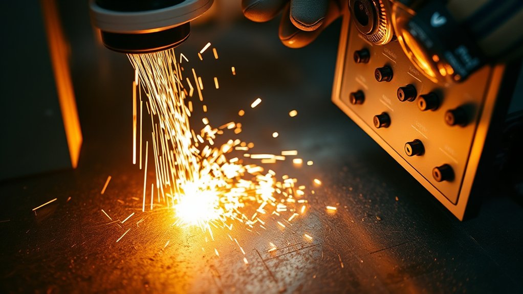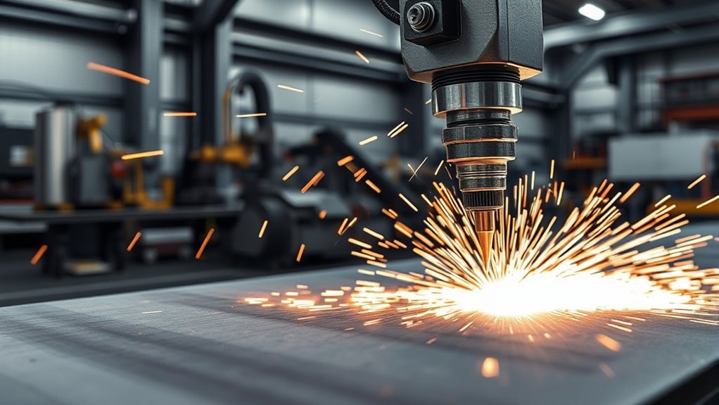
Clean plasma cuts come from a controlled process, not one “magic” setting. If the edge is rough, rounded, beveled, or covered with dross, first compare the job with your machine’s cut chart. Then check cut direction, consumables, torch height, speed, gas delivery, work-lead contact, and table motion in a fixed order.
Quick Answer
To improve plasma cutting quality, load the manufacturer’s cut-chart settings for the exact material, thickness, amperage, gas, and consumables. Square the torch, verify pierce and cut height, use clean gas, and make short test cuts. Diagnose dross by its location and texture, then change only one setting at a time.
Key Takeaways
- Start with the cut chart for your exact torch, consumables, material, thickness, and gas process.
- Read the defect before adjusting the machine: hard bottom dross, bubbly dross, top spatter, bevel, and incomplete cuts point to different causes.
- Keep the torch square, the plate supported, and the torch-to-work distance stable.
- Inspect each consumable by its manufacturer’s wear limits; cartridge systems are replaced as a unit.
- Use clean, dry gas at the required flowing pressure and keep the work lead on clean, conductive metal.
- Change one variable at a time and record the result so a speed problem is not confused with a height, gas, or motion problem.
At a Glance
| Time Required | About 15–30 minutes for inspection and test cuts |
| Difficulty | Moderate; basic CNC and plasma-system knowledge helps |
| Tools Needed | Machine manual and cut chart, scrap from the same plate, square, straightedge, consumable tool, and basic gas-line inspection supplies |
| Cost | Usually no cost for setting changes; replacement consumables, filters, or damaged motion parts vary by system |
What’s in This Article
- Plasma Cutting Safety Before Troubleshooting
- Pre-Cut Baseline Checklist
- Diagnosing Plasma Cut Defects
- Plasma Arc Direction and Its Impact on Cut Quality
- Selecting the Correct CNC Plasma Cutter Settings
- Evaluating and Replacing Worn Plasma Consumables
- Ensuring Proper Torch Alignment and Squaring
- Importance of Torch-to-Work Distance
- Adjusting Cutting Speed for Optimal Performance
- Addressing Gas Delivery System Issues
- Checking Work Lead, Input Power, and Piercing
- Minimizing Torch Vibration and Its Effects
- Tuning the Plasma Cutting Table for Better Results
- Common Plasma Cutting Mistakes That Hurt Edge Quality
- Frequently Asked Questions
- Conclusion
- Sources
Plasma Cutting Safety Before Troubleshooting
Plasma cutting creates an intense arc, ultraviolet radiation, hot slag, sparks, noise, fumes, electrical hazards, and moving-machine hazards. Follow the plasma-system manual, your workplace hot-work procedure, and applicable safety rules before making a test cut. OSHA identifies metal fumes, UV radiation, burns, eye injury, and electric shock among the main welding and cutting hazards.
Warning: Wear the eye, face, hearing, hand, foot, and flame-resistant protection required for the process. Use effective local exhaust or other suitable ventilation. Remove or shield combustible material, keep people clear of CNC motion, and never cut a sealed container or unknown coated metal until it has been identified and made safe.
Disconnect and lock out power before opening the power supply, servicing the torch, or touching internal electrical parts. Stored energy can remain after the machine is switched off. Do not bypass guards, interlocks, torch-height controls, or crash protection.
When using bottled process gases, secure cylinders and follow the gas supplier’s handling rules. Oxygen and hydrogen processes require equipment designed for those gases and stricter fire controls. Never substitute a gas that is not listed for your torch and process.
Pre-Cut Baseline Checklist
Before changing a setting, return the system to a known baseline. This prevents several small faults from hiding each other.
- Identify the job: Confirm material type, measured thickness, desired edge quality, and whether the feature is an outside contour, slot, or hole.
- Load the correct process: Match amperage, consumables, gas, cut speed, pierce height, cut height, pierce delay, and arc-voltage setting to the manufacturer’s cut chart.
- Inspect the torch: Install the correct parts in the correct order and check the nozzle orifice, electrode, shield, swirl ring, retaining cap, O-rings, and cartridge condition.
- Check mechanics: Square the torch from the front and side, confirm the mount is tight, support the plate, and remove slag that prevents the sheet from sitting flat.
- Check utilities: Verify clean gas, sufficient pressure while gas is flowing, a clean work-lead connection, stable input power, and correct machine mode.
- Cut a sample: Use scrap from the same plate and inspect the top edge, cut face, bottom edge, bevel, kerf width, and lead-in area.
The fastest way to lose a dross-free setting is to change speed, height, amperage, and gas pressure at the same time.
Diagnosing Plasma Cut Defects
Inspect both the finished part and the scrap. The location, shape, and hardness of the defect usually narrow the cause.
| Defect | Likely Causes | First Checks |
| Small, hard bead on the bottom | Speed too high, torch too high, amperage too low for the selected process, or worn nozzle | Confirm the cut chart, inspect the nozzle, then reduce speed in small steps |
| Large, soft or bubbly bottom dross | Speed too low, excess heat input, or wrong process for the thickness | Increase speed in small steps and recheck amperage and material thickness |
| Top spatter or a rounded top edge | Torch too high, excessive speed, worn nozzle, or unstable plate height | Check cut height, arc voltage, nozzle condition, and plate support |
| Bevel on every side | Incorrect cut height, wrong process, or speed outside the recommended range | Return to cut-chart height and speed before fine-tuning |
| Bevel mainly on one side | Torch not square, damaged nozzle, incorrect cut direction, or loose mount | Square the torch, rotate or replace the nozzle as the manual allows, and verify toolpath direction |
| Arc does not fully penetrate | Speed too high, wrong amperage or mode, low gas flow, poor work-lead contact, weak input power, or thickness beyond the process | Stop the cut and verify the complete setup; do not keep slowing the machine without checking the other causes |
| Rough face, chatter, or jagged holes | Worn consumables, vibration, loose drive parts, poor acceleration settings, or unstable gas | Inspect the torch and motion system before changing amperage |
Plasma Arc Direction and Its Impact on Cut Quality
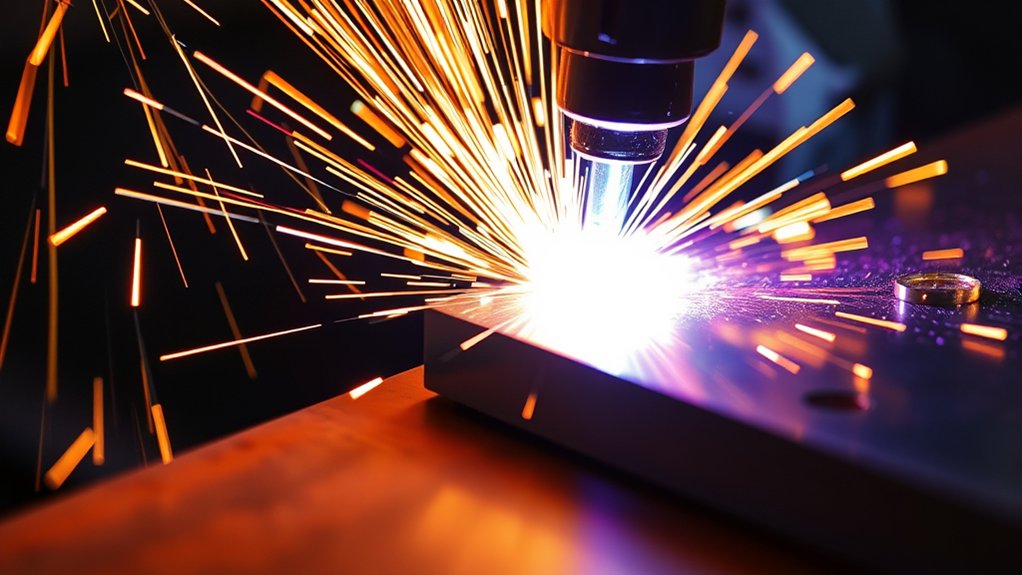
Plasma arc direction affects which side of the kerf receives the squarer edge. With common consumables that create a clockwise gas swirl, the better edge is on the right side of the torch’s forward travel. For an outside contour, that usually means clockwise travel. For an inside hole or slot, it usually means counterclockwise travel.
Keep the finished part on the good side of the arc and the scrap on the other side. Confirm this rule in the manual because torch and consumable designs can differ.
Precise torch alignment also matters. A torch that leans can create one-sided bevel, uneven kerf width, and abnormal consumable wear. Correct gas flow supports arc stability and helps the jet remain focused.
Selecting the Correct CNC Plasma Cutter Settings
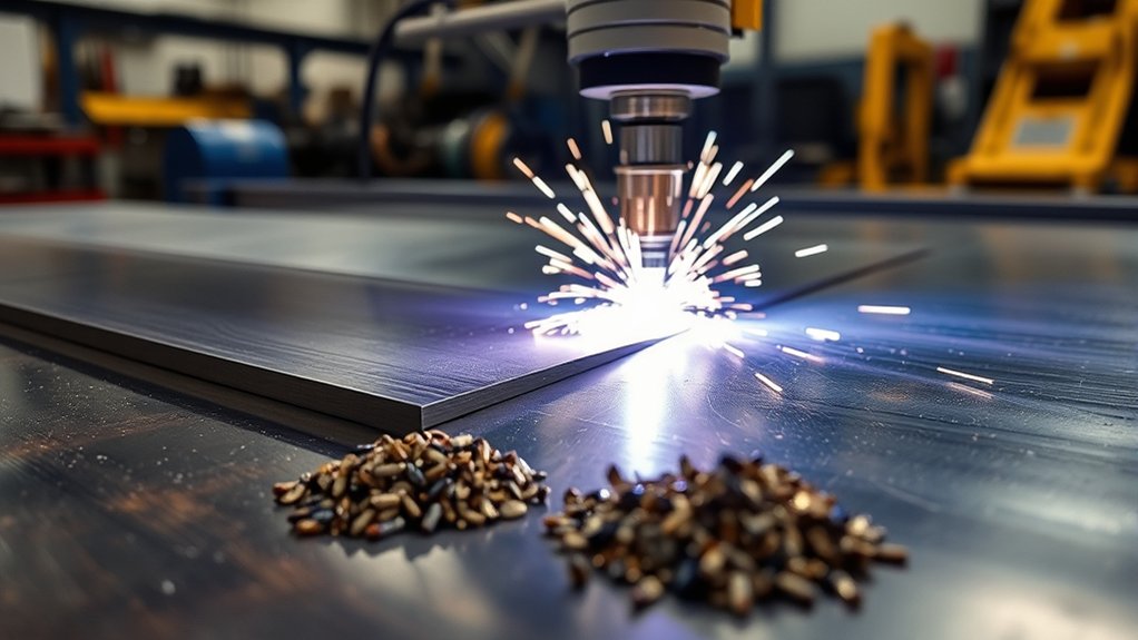
Good CNC plasma cutter settings start with the material, measured thickness, consumable set, and required edge quality. Match amperage, speed, pierce height, cut height, pierce delay, gas process, and arc voltage to the cut chart for your machine.
Manufacturer cut charts are the baseline, not a rough suggestion. Use the exact row for the torch and consumables, then fine-tune with short test cuts on scrap from the same plate. Do not mix settings from a different torch family or amperage set.
Lower-amperage consumables often produce better detail and angularity on thin material when the system supports them. Higher current can improve productivity or thickness capacity, but it does not correct a bad height, wrong speed, poor gas supply, or worn nozzle.
Products Worth Considering

Package Include: 10 Shield Cups, 50 Nozzles, 20 Swirl Baffle, and 30 Electrodes.

Drag-Cut Control & Manual Versatility: Rest the torch tip directly on sheet metal to eliminate standoff fatigue. Perfect for hand-tracing rulers, custom HVAC ducting layouts, and intricate metal art scaling before moving to automated runs.

[Achieve Precise Cuts] PT31 Plasma Cutting Consumables – Your Essential Tool for Efficient Cutting! Whether you're working with sheet metal, steel, or any other material, superior cutting performance ensure clean, accurate, and smooth cuts.
Optimal Speed Selection
Selecting the right cutting speed helps reduce dross formation. Excessive speed can make the arc lag, narrow the kerf, increase bevel, and leave a small hard bead on the bottom. A speed that is too low can widen the kerf, overheat the edge, and leave larger, softer deposits.
Your goal is the lowest-dross operating window for the selected material and process. That window changes with plate chemistry, thickness, gas, consumable condition, cut height, and machine motion.
Run test cuts with small speed changes. Keep every other variable fixed during the test, or a height or gas problem may be mistaken for a speed problem.
Material Thickness Considerations
Material thickness controls the energy and pierce time needed for the cut. Thicker plate commonly requires a process with more current, a lower travel speed, and a longer pierce delay, but the approved cut chart—not a general rule—sets the values.
- Measure the plate: Do not rely only on the nominal label when scale, coating, or plate variation could affect the setup.
- Choose the process: Select a consumable and amperage range rated for the thickness.
- Select the approved gas: Use only a gas process listed for the torch, material, and thickness.
- Load the full cut-chart row: Speed, heights, delay, voltage, and kerf compensation work as a set.
- Monitor the cut: Stop if the arc fails to penetrate or the torch begins to contact the plate.
These steps reduce cleanup, protect the torch, and avoid wasting plate.
Evaluating and Replacing Worn Plasma Consumables
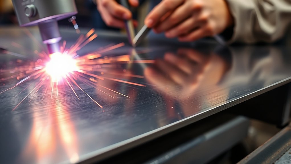
Regular inspection of plasma consumables protects cut quality and reduces dross. On a traditional stack, check the nozzle, electrode, shield, swirl ring, retaining cap, and O-rings for wear, heat damage, contamination, or blocked gas passages. On a cartridge system, inspect and replace the cartridge as the manufacturer directs.
A nozzle orifice should remain round and centered. An enlarged, notched, or elliptical opening can make the arc wander and create uneven bevel. Inspect electrode wear with the correct gauge or wear limit for that torch; do not guess from another system’s pit-depth rule.
Signs of worn or damaged parts include a wider kerf, rough edge, poor piercing, inconsistent starts, arc wander, and bevel that changes when the consumables are rotated or replaced.
Use parts that match the torch, amperage, and process. Mixing incompatible parts can disrupt gas flow, reduce arc stability, and damage the torch. Replace components individually or as a set only when the system manual calls for that procedure.
Apply only the specified O-ring lubricant in a very light film. Excess lubricant can collect dirt or block gas passages, while the wrong lubricant can damage seals.
Pro Tip: Keep a cut log with material, thickness, process, pierce count, arc-on time, defect, and the part that fixed it. Replace parts by condition and the manufacturer’s limits, not by a universal number of cuts.
Products Worth Considering

PACKAGE INCLUDED: 5 Pcs Cup-15 Pcs Electrodes-10 Pcs Ring-30 Pcs Tip(Standard)

Package Include: 5 Shield Cups, 30 Nozzles, 10 Swirl Baffle, and 15 Electrodes.

Fit for: SG-55 AG-60 plasma cutter torch head.
Ensuring Proper Torch Alignment and Squaring
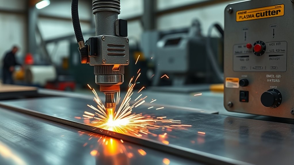
A square torch helps produce straighter cuts, cleaner holes, and consistent bevel. If the torch leans, the arc enters the metal at an angle and one side of the cut usually becomes worse than the other.
Check the torch from the front and side before production. Tighten the mount and confirm it does not shift during acceleration, cornering, piercing, or a torch-height move. Inspect the holder after every crash.
Support warped material as flat as practical. Poor plate support changes the torch-to-work distance and can cause the height control to chase movement that the table cannot follow.
Leveling Workpiece Importance
Leveling the workpiece helps maintain a consistent cutting height. A flat plate also gives initial height sensing and arc-voltage control a more stable surface to follow.
- Check flatness: Use a straightedge to find bowing, lifted corners, and slag under the plate.
- Secure the plate: Use safe hold-down methods when movement could affect accuracy.
- Square the torch: Check perpendicular alignment in both machine axes.
- Recheck after service: Confirm alignment after a crash, torch replacement, gantry adjustment, or table maintenance.
These checks can prevent hours of grinding, hole correction, or part rework.
Torch Mounting Stability
Torch mounting stability controls how smoothly the arc follows the programmed path. A loose holder can create chatter marks, jagged corners, inconsistent kerf width, and changing bevel.
Check mount fasteners, breakaway alignment, cable drag, and torch-lead strain. A lead that pulls on the torch during travel can tilt the holder even when the mounting bolts are tight.
Maintain the torch, gantry, rails, bearings, belts, racks, gears, and slats so the machine can repeat the same path without backlash or vibration.
Material Warping Effects
Heat from plasma cutting can make thin or poorly supported material move during the cut. This changes torch height, hole shape, and edge angle.
Use suitable support, hold-down methods, and cut sequencing to spread heat. On thin sheet, avoid toolpaths that trap too much heat in one area or leave a small part free to tip into the torch.
- Square the torch: Confirm it is perpendicular before blaming the plate.
- Level the surface: Start with the flattest plate condition available.
- Plan the sequence: Spread cuts across the sheet and finish heat-sensitive details before the plate moves.
- Correct severe warp: Flatten or replace material that the torch-height system cannot safely follow.
- Secure the mount: Make sure vibration or cable pull does not change the torch angle.
Importance of Torch-to-Work Distance
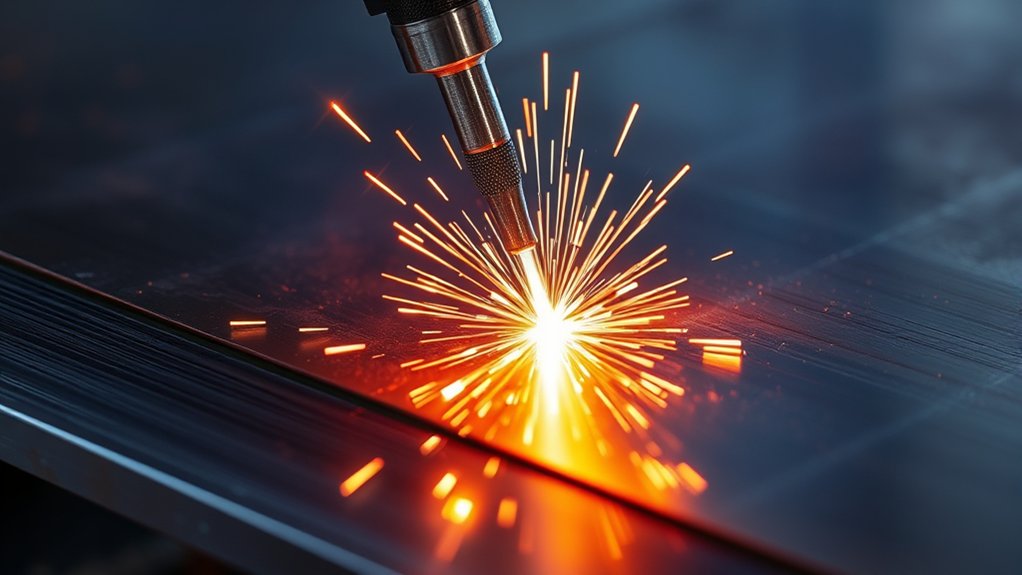
Torch-to-work distance strongly affects arc shape, cut angle, top-edge rounding, dross, and consumable life. The correct pierce height, transfer height, cut height, pierce delay, and arc voltage are system-specific. Use the exact values in the cut chart instead of a universal inch measurement.
As a broad rule for many mechanized systems, pierce height is higher than cut height so molten metal does not blow back into the nozzle. Hypertherm describes a typical pierce-height range of about 150%–200% of cut height, but your machine’s chart takes priority.
A torch that cuts too high can widen the kerf, round the top edge, and create positive bevel. A torch that cuts too low can create negative bevel, double arcing, nozzle contact, or damage from molten spatter.
An automatic height control system uses arc voltage to maintain distance while the plate changes height. It works only when the target voltage, consumables, work connection, gas process, and machine motion are correct. Worn consumables lengthen the arc and can require the adjustment method specified by the manufacturer.
Note: Disable or freeze arc-voltage height correction during programmed slowdowns, small holes, sharp corners, and kerf crossings when your CNC or height controller requires it. Otherwise, the temporary voltage rise can drive the torch toward the plate.
Adjusting Cutting Speed for Optimal Performance
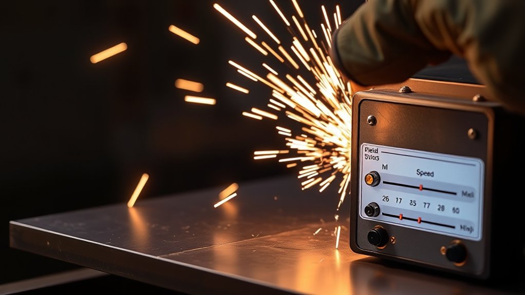
Fine speed control helps balance edge quality, low dross, and part accuracy. Begin at the cut-chart speed and inspect the arc, spark stream, kerf, cut face, and bottom edge.
- Make a baseline cut: Use the listed speed before making a change.
- Identify the dross type: A small hard bead often points toward excessive speed; a large soft deposit often points toward insufficient speed.
- Change speed in small steps: Use the increment recommended by the manufacturer or a consistent percentage change.
- Keep height fixed: Confirm that the torch-height control is not moving differently between tests.
- Check feature slowdowns: Corners and small holes may need special feed rates, lead-ins, and height-control rules rather than a lower speed for the whole program.
- Record the cleanest range: Save the result with the plate and process information.
Do not change several variables at once. Adjust one setting, inspect the edge, and record the result before making the next change.
Addressing Gas Delivery System Issues
Correct speed cannot overcome poor gas delivery. Gas type, purity, pressure, flow, filtration, hose size, fitting restriction, and leak condition all affect arc stability and edge quality.
Start with a gas leak inspection using the safe method in the system or gas-supply manual. Check pressure while gas is flowing at the point the manufacturer specifies. A regulator can show adequate static pressure while the pressure falls below specification during preflow, pierce flow, or cutting.
Long hoses, undersized fittings, clogged filters, damaged regulators, compressor cycling, and high shop demand can reduce flow at the torch. If quality changes during a long run, check the compressor duty cycle, dryer, separator, filter element, and line temperature.
Use clean, dry, oil-free air or the listed process gas. Moisture, oil, and dirt can disrupt the arc, shorten consumable life, and damage internal parts.
Choose Gas by System and Material
- Air plasma systems: Use the clean, dry air or nitrogen approved by the manufacturer. Do not connect oxygen merely because it can improve mild-steel quality on a different class of machine.
- Multi-gas mild-steel processes: Oxygen plasma can provide excellent mild-steel cut quality when the complete system is designed and approved for oxygen.
- Stainless steel and aluminum: Air, nitrogen, mixed gases, or argon-hydrogen may be listed depending on the system, thickness, and quality goal.
- Hydrogen-containing mixtures: Use only approved equipment, ventilation, storage, and fire controls. Never improvise a mixture.
Gas recommendations are not interchangeable across machines. Follow the torch manual and cut chart for the exact process.
Checking Work Lead, Input Power, and Piercing
A poor return-current path can look like a consumable, speed, or gas problem. Attach the work lead to clean, conductive metal as close to the cutting area as practical and in the location recommended by the machine builder. Remove rust, paint, scale, or slag that prevents solid contact.
Confirm that the power source receives the required input voltage and phase under load. Undersized extension cords, long cable runs, weak generators, or overloaded circuits can reduce performance. Use only cable sizes and generator ratings approved by the manufacturer.
Pierce Height, Delay, and Lead-In
Set pierce height and delay from the cut chart. Piercing too low can drive molten metal into the nozzle and cause early failure. Piercing too high can prevent transfer or stretch the arc. The torch should begin moving only after the arc has pierced the plate, but an excessive delay can overheat the start area.
Use a lead-in that lets the torch reach cut height and stable motion before it reaches the finished contour. Place the pierce in scrap whenever possible. For small holes, use the machine builder’s hole-cutting rules for lead-in shape, reduced feed rate, height-control behavior, and lead-out. Avoid a lead-out that crosses the kerf with the arc still on unless the process specifically calls for it.
Minimizing Torch Vibration and Its Effects
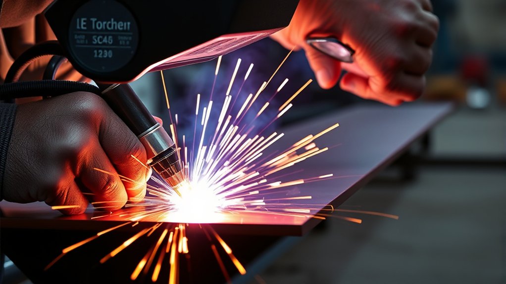
Torch vibration can leave rough surfaces, jagged lines, inconsistent kerf, and poor holes. These defects may be especially visible on thin sheet and small features because the machine changes direction quickly.
Use these checks to reduce vibration:
- Secure the mount: Tighten the holder and inspect the breakaway after a crash.
- Control cable pull: Make sure the torch lead and cable carrier do not tug on the torch.
- Match speed to motion limits: A table that cannot hold the programmed acceleration will overshoot corners or chatter on curves.
- Maintain torch height: Prevent the arc from wandering across the kerf.
- Inspect motion parts: Check rails, bearings, belts, racks, pinions, gears, couplers, and gantry alignment.
Motion quality matters as much as electrical settings. A tuned table lets the torch follow curves, corners, and small holes without visible chatter.
Tuning the Plasma Cutting Table for Better Results

Your plasma cutting table must move smoothly and hold the programmed settings. Gas flow, torch height, speed, grounding, electrical input, and table motion work together.
Calibrate axis travel, square the gantry, and verify backlash before tuning the plasma process. Then inspect consumables, clean the torch, check the work lead, confirm gas pressure, and test initial height sensing.
Review acceleration, cornering, and small-feature settings. If the machine slows sharply while arc-voltage control remains active, the torch-height controller may react to the longer arc and move the torch too close to the plate. Use the CNC and height-control features intended for corners, holes, kerf crossings, and deceleration.
Routine maintenance keeps cuts repeatable. Clean rails, inspect drives, remove slag from slats, drain or service the water table as required, and replace damaged supports before they affect plate height.
After mechanical work, repeat a square test, circle test, and straight test cut before returning to production.
Common Plasma Cutting Mistakes That Hurt Edge Quality
Many edge problems come from a small group of setup mistakes. Check these items before assuming the power supply needs major repair.
- Skipping the cut chart: Settings from another machine, torch, material, or amperage set may be unsafe or ineffective.
- Changing several variables: Multiple changes hide the true cause and make the result hard to repeat.
- Using worn or mismatched consumables: Damaged parts can make the arc wander, widen the kerf, and create uneven bevel.
- Ignoring pierce settings: Wrong height or delay can damage parts and roughen the lead-in area.
- Cutting warped or poorly supported plate: Changing plate height can cause bevel, height-control errors, or torch crashes.
- Overlooking gas quality: Wet, oily, dirty, restricted, or low-flow gas can shorten consumable life and destabilize the arc.
- Using a poor work connection: Rust, paint, scale, or a loose clamp can interrupt current flow.
- Ignoring table motion: Backlash, vibration, cable drag, and poor acceleration settings can ruin holes and corners even when the plasma settings are correct.
- Trying to cut beyond the rated process: Repeatedly slowing the torch is not a safe substitute for a process rated for the plate.
Fix the easiest baseline issues first: correct process, correct parts, clean gas, solid work connection, square torch, proper height, and stable motion. Then tune speed with controlled test cuts.
Frequently Asked Questions
How does material thickness affect dross formation?
Thickness changes the current, speed, pierce delay, and gas process needed to remove molten metal from the kerf. Use the cut-chart row for the measured thickness. A process that is too weak may leave hard dross or fail to penetrate, while too much heat or too little speed can leave larger, softer deposits.
What role does amperage play in edge finish quality?
Amperage controls the cutting current, but it must match the nozzle, material, thickness, and speed. Too little current for the selected speed may cause lag and incomplete cutting. An oversized process on thin metal may reduce detail and increase heat input. Use the approved consumable set instead of turning the current outside its rated range.
Can environmental conditions influence plasma cutting results?
Yes. High humidity can increase moisture in compressed air, cold weather can affect condensation and machine motion, and heavy shop demand can lower air pressure. Dirt, fumes, and slag can also affect filters, rails, plate support, and electrical contact. Maintain the machine for the actual shop conditions.
How do different gases impact dross control?
Gas affects arc energy, molten-metal removal, edge chemistry, speed, and the width of the low-dross operating window. Air is common on portable systems. Approved oxygen processes can improve mild-steel quality, while nitrogen or mixed gases may suit stainless steel and aluminum. Use only gases listed for your system.
What is the effect of electrode wear on cutting efficiency?
Electrode wear can destabilize the arc, slow or interrupt starts, damage the nozzle, and make cuts inconsistent. Inspect the electrode with the wear criteria for that torch. Replace it, the related stack parts, or the complete cartridge as the manufacturer directs.
Why does my plasma cut have bevel on one side?
One-sided bevel often points to torch tilt, a damaged nozzle, a loose holder, or the finished part being on the wrong side of travel. Square the torch in both axes, verify cut direction, inspect the nozzle, and make a straight test cut in two directions.
How can I tell if dross comes from speed or torch height?
Speed-related dross usually changes in a consistent way when speed is adjusted in small steps. Height problems often appear with top-edge rounding, a wider kerf, changing bevel, or nozzle contact. Lock in the cut-chart height first, verify the height controller, and then run a controlled speed test.
What causes top-edge rounding on a plasma cut?
Common causes include excessive cut height, an arc-voltage setting that holds the torch too high, excessive speed, worn consumables, or a process that is not matched to the thickness. Start with the listed cut height and inspect the nozzle before changing current.
Why does the plasma arc stop cutting through the plate?
Possible causes include excessive speed, low gas flow, wrong mode or amperage, worn consumables, poor work-lead contact, low input power, or a process that is not rated for the thickness. Stop and verify the full setup rather than repeatedly slowing the machine.
How often should plasma consumables be replaced?
There is no universal cut count. Life changes with current, material, pierce technique, gas quality, cooling, starts, and operator setup. Inspect parts regularly and replace them at the wear limit or when cut quality and starts no longer meet the manufacturer’s standard.
Conclusion
Better plasma cutting quality starts with a repeatable baseline. Use the correct cut-chart process, keep the torch square, maintain clean gas and a solid work connection, inspect consumables, and control pierce and cut height. Read the defect before making an adjustment, change one variable at a time, and confirm the result on matching scrap. This method reduces dross, protects the torch, and makes clean cuts easier to repeat.
Sources
- Hypertherm: Basic tips to improve plasma cut quality — cut direction, cut-chart settings, torch squareness, and torch height
- Hypertherm: Troubleshooting excessive dross — high-speed dross, top spatter, and the low-dross operating window
- Hypertherm: Torch height control for plasma cutting — pierce height, arc voltage, and height-related bevel
- Hypertherm: Extending plasma consumable life — nozzle and electrode inspection, gas flow, leaks, and pierce damage
- Hypertherm: Plasma gas selection guide — material-specific gas choices and system compatibility
- OSHA: Welding, cutting, and brazing hazards and solutions — fumes, UV radiation, burns, electrical shock, and PPE