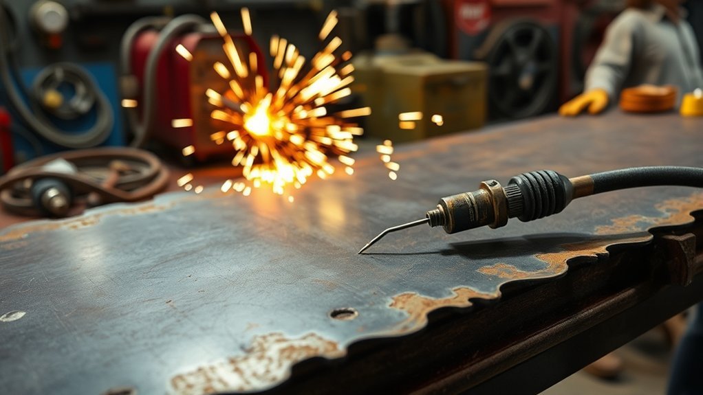
A tiny gap between the plasma torch and the metal can change edge angle, kerf width, dross, and consumable life. The correct gap is not one universal number: it depends on the torch, consumables, amperage, material, thickness, and whether you are cutting by hand or on a CNC table. This guide shows how to find the correct cut height, set pierce height, and keep both consistent.
Quick Answer
Use the cut height in your plasma cutter’s manual or cut chart—not one universal gap. Many mechanized air-plasma processes use about 0.06 inch (1.5 mm), handheld standoff torches often use about 1/8 inch (3 mm), and drag-shield torches may touch the plate. Pierce height is usually higher and must also follow the chart.
Key Takeaways
- Start with the manufacturer’s cut chart for your exact torch, consumables, amperage, material, and thickness.
- Do not apply a blanket 1/16- to 1/8-inch rule to every plasma cutter; drag shields, unshielded tips, FineCut processes, and machine torches use different heights.
- Pierce height is higher than cut height. A common rule is 150% to 200%, but some official cut charts specify 250% to 400%.
- On CNC tables, initial height sensing and torch height control help maintain standoff, but height control may need to be locked or disabled on small holes and slow corners.
- Height is only one cut-quality variable. Travel speed, amperage, air quality, consumable condition, torch angle, and the work connection also matter.
At a Glance
| Time Required | About 5–10 minutes for setup and a scrap test |
| Difficulty | Beginner for handheld cutting; intermediate for CNC torch height control |
| Tools Needed | Operator manual or cut chart, standoff gauge or suitable spacer, scrap metal, PPE, and optional torch height controller |
| Cost | Usually no added cost when using the supplied chart and basic measuring tools; optional CNC sensing hardware varies by system |
What’s in This Article
- Understanding Tip Height in Plasma Cutting
- How to Set Plasma Cutter Tip Height
- Starting Heights for Different Torch Types and Processes
- How Tip Height Affects Cut Quality and Precision
- Adjusting Tip Height for Intricate Designs and Small Holes
- Common Mistakes With Torch Height and How to Avoid Them
- Tools and Techniques for Maintaining Consistent Standoff
- Factors Influencing Ideal Tip Height Settings
- The Role of Technology in Managing Torch Height
- Tips for Effective Arc-Voltage Height Control
- Frequently Asked Questions
Understanding Tip Height in Plasma Cutting

“Tip height” is often used as a general term, but plasma manuals usually separate three settings:
- Cut height: The distance between the shield or nozzle and the workpiece while the torch is moving through the cut.
- Initial pierce height: The greater distance used when the arc first pierces the plate, helping keep molten metal away from the nozzle and shield.
- Transfer height: On some mechanized systems, the height at which the pilot arc transfers to the plate before the torch moves to pierce or cut height.
The correct value comes from the cut chart for the exact process. For example, the Hypertherm Powermax45 machine-torch cut charts specify a 0.06-inch (1.5 mm) cut height for many 45-amp shielded processes, while some FineCut stainless processes use 0.02 inch (0.5 mm). That difference is why a universal standoff rule can produce poor results.
The right starting height is the number in the cut chart for your exact process—not a number copied from a different machine or consumable set.
How to Set Plasma Cutter Tip Height
1. Identify the Torch and Consumables
Confirm whether the torch uses a drag shield, an exposed or unshielded nozzle, a machine shield, or a special process such as FineCut. Also confirm the installed amperage-rated consumables. Two consumable sets used on the same power supply can require different heights.
2. Find the Correct Cut-Chart Row
Match the material, thickness, amperage, gas, and consumable set. Record the cut height, initial pierce height, pierce delay, travel speed, and arc-voltage setting when the chart provides one. Treat these values as a tested starting point rather than mixing settings from several rows.
3. Set the Physical Height
For a handheld standoff torch, use the manufacturer’s supplied guide, a standoff attachment, or a correctly sized nonconductive gauge. A drill-bit shank can serve as a quick gauge only when the power is off and the torch cannot fire. For a drag-shield torch, rest the shield—not an unprotected nozzle—on the plate when the manual permits drag cutting.
4. Set Pierce Height and Delay
Use the charted pierce height. When no chart is available, the manufacturer’s general guidance may call for piercing at roughly 150% to 200% of cut height, but official charts can specify more. Do not guess on thick plate; use an edge start or rolling pierce when the manual requires it.
5. Make a Scrap Test
Cut a straight line and a small test shape in scrap of the same material and thickness. Check the top edge, bevel, dross, kerf, and whether sparks exit through the bottom. Correct travel speed and consumable condition before making large height changes.
Warning: Turn off and isolate the plasma cutter before placing a gauge near the torch or touching consumables. Never put a metal spacer between an energized torch and the workpiece.
Starting Heights for Different Torch Types and Processes
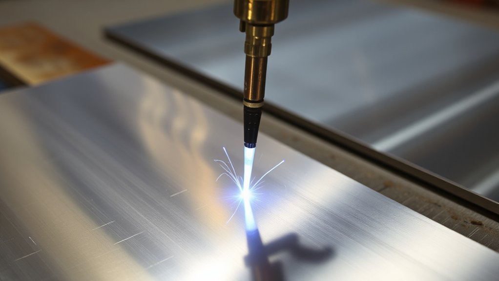
Material type alone does not determine standoff. Torch design, consumables, current, gas, and plate thickness all influence the charted setting. Use the ranges below only to understand common patterns, then verify your manual.
| Torch or Process | Common Starting Approach | Important Limit |
|---|---|---|
| Handheld drag-shield torch | Shield may ride directly on the workpiece | Drag only when the manual and installed shield allow it |
| Handheld standoff torch | Often around 1/8 inch (3 mm) | Use the model-specific guide or manual value |
| Mechanized shielded air plasma | 0.06 inch (1.5 mm) is common in some Powermax cut charts | Not universal across brands, currents, or consumables |
| Fine-feature or FineCut process | May use 0.02–0.06 inch (0.5–1.5 mm) | Small changes have a large effect; follow the exact chart |
| Thick plate near the pierce limit | Charted cut height may stay the same while pierce height and delay increase | An edge start may be required instead of a center pierce |
Note: Mild steel, stainless steel, and aluminum may share the same cut height in one manufacturer’s chart. The speed, voltage, gas, kerf, and pierce settings can still differ. Do not lower stainless steel automatically or raise the torch only because the plate is thicker.
How Tip Height Affects Cut Quality and Precision
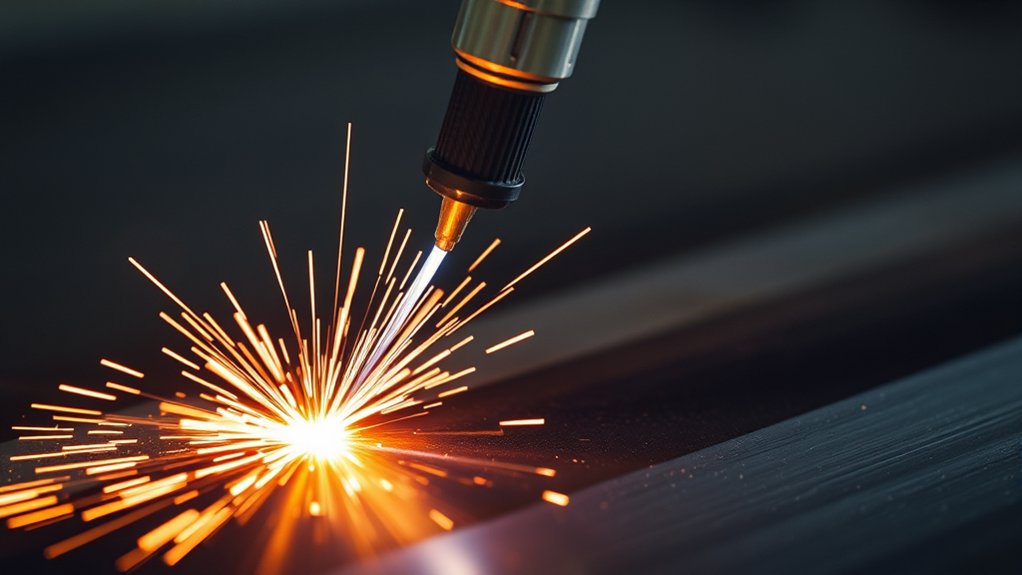
Torch height changes arc length. With other conditions held steady, a longer arc generally produces a higher measured arc voltage, while a shorter arc produces a lower voltage. Height changes can affect edge angle, kerf width, arc stability, and consumable life, but the visible defect must be diagnosed with travel speed, torch angle, and consumable condition in mind.
Impact on Arc Stability
If the torch is far above the charted cut height, the arc stretches and can lose energy before it reaches the plate. The cut may fail to penetrate, the kerf may widen, and the arc may extinguish. If the torch is too low, molten metal can strike the front of the torch, the nozzle can contact the plate, and the arc can become unstable.
Influence on Kerf Width and Edge Angle
A torch that is too high commonly creates a wider kerf and a positive bevel, with more material removed near the top. A torch that is too low can produce a negative bevel. Hypertherm’s cut-quality troubleshooting guidance recommends raising or lowering the torch based on the observed cut angle, after confirming the torch is square to the plate.
Effect on Dross Formation
Incorrect height can contribute to dross, but travel speed is often the main clue. Low-speed dross forms when the torch moves too slowly and the arc removes more material than the gas stream can clear. High-speed dross forms when the torch moves too quickly and the arc trails behind. Check the charted speed, amperage, gas flow, and consumables before treating every dross problem as a height problem.
| Symptom | Possible Height Cause | What to Check Next |
|---|---|---|
| Wide kerf or positive bevel | Torch may be too high | Torch squareness, speed, voltage, worn nozzle |
| Negative bevel or nozzle contact | Torch may be too low | Plate warp, initial height sensing, shield condition |
| Heavy dross | Height may be wrong | Travel speed, amperage, gas quality, consumables |
| Arc misfire during piercing | Pierce height may be too high | Work clamp, transfer distance, gas pressure, consumables |
| Rapid nozzle or shield damage | Pierce height may be too low | Pierce delay, plate thickness, center-pierce rating |
Adjusting Tip Height for Intricate Designs and Small Holes
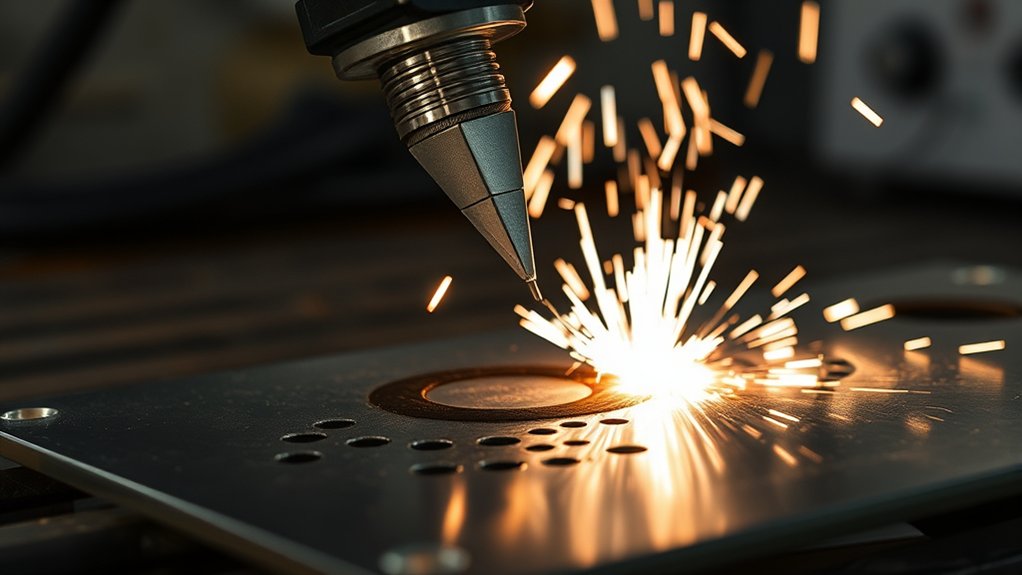
Small holes and tight corners are difficult because the machine slows down. When speed drops, arc voltage can rise even though the physical torch-to-work distance has not changed. A voltage-based torch height controller may interpret that rise as extra height and drive the torch downward.
For better hole quality:
- Use the cut chart or manufacturer’s hole-cutting process when one is available.
- Keep the torch square and use fresh, correctly matched consumables.
- Use accurate kerf compensation and a lead-in that does not damage the finished edge.
- Lock, freeze, or disable voltage-based height control during small holes and slow corners when the CNC or manufacturer recommends it.
- Maintain the programmed cut height instead of letting the torch chase voltage around the circle.
Hypertherm notes in its hole-quality guidance that voltage-regulated height control can worsen small-hole quality on some systems. Automatic control is valuable, but it must be configured for the geometry being cut.
Common Mistakes With Torch Height and How to Avoid Them
- Using one gap for every job: A 1/16- or 1/8-inch setting may be correct for one process and wrong for another. Use the exact cut chart.
- Dragging an unprotected nozzle: Only drag a torch when the installed shield and manual permit it.
- Piercing at cut height: This exposes the front of the torch to molten blowback and can damage consumables quickly.
- Changing height before checking speed: Dross and bevel can also come from incorrect travel speed, amperage, gas flow, or worn parts.
- Ignoring plate warp: Thin sheet can rise toward the torch as it heats, changing the actual gap during the cut.
- Leaving THC active everywhere: Voltage control may dive in corners, at the end of a cut, or around small holes unless the CNC uses anti-dive or voltage lockout.
- Calibrating with worn consumables: Arc voltage rises as consumables wear, so an old voltage value may no longer hold the intended physical height.
Warning: Piercing too low can send molten metal into the nozzle or shield, causing immediate damage. Do not center-pierce material thicker than the system’s rated pierce capacity; use an edge start or the manufacturer’s approved rolling-pierce method.
Tools and Techniques for Maintaining Consistent Standoff
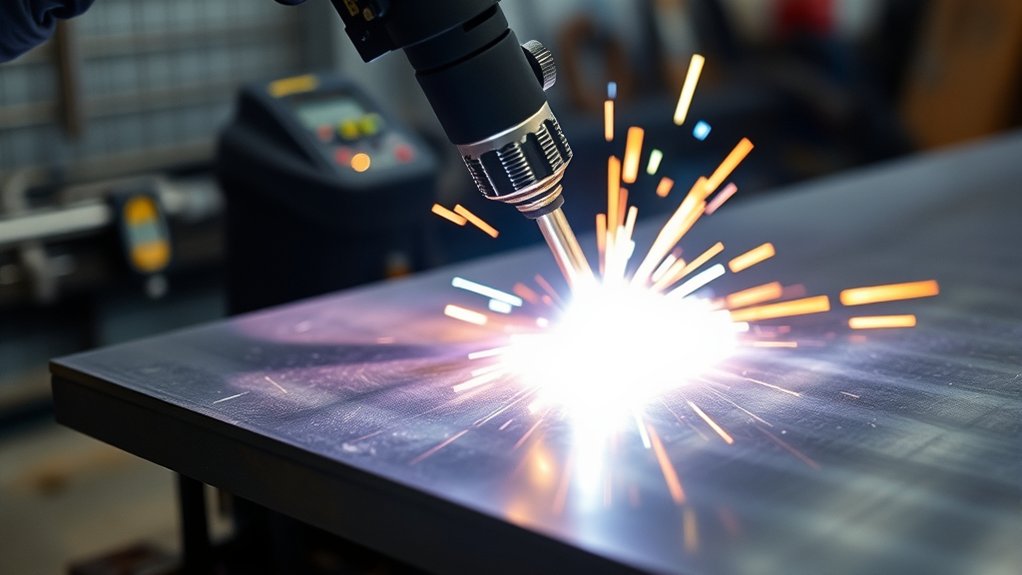
- Manufacturer standoff guide: The safest manual option because it matches the torch design.
- Standoff gauge or spacer: Useful for a repeatable setup when the machine is off and isolated.
- Drag shield: Maintains the designed gap internally while the shield rides on the plate.
- Initial height sensing: Finds the plate surface before each pierce through ohmic contact, a floating head, or another sensing method.
- Automatic torch height control: Adjusts Z-axis position from arc-voltage feedback after the torch reaches steady cutting conditions.
- Manual verification: A periodic physical height check catches incorrect voltage calibration, plate movement, loose torch mounts, or worn consumables.
Pro Tip: Write the charted cut height, pierce height, delay, speed, and voltage on the job sheet. Keeping the settings together prevents a correct height from being paired with the wrong speed or consumables.
Products Worth Considering

Standard size plasma torch double pointed spacer guide for: PT-60 / PT-40

Upgrade Double Wheel Spacer Roller Guide: Our double wheel roller guide is specifically designed to fit PT-31 torch / LG-40 torch, ensuring optimal balance during cutting. Experience improved cutting performance with WeldingStop PT31 torch.

The comsumables fit torch: AG60 / AG-60 / SG55 / SG-55 plasma cutting torch
Factors Influencing Ideal Tip Height Settings
The correct height is part of a complete process setting. Review these factors together:
- Torch and consumable design: Shielded, unshielded, drag, precision, and high-amperage parts use different standoffs.
- Material and thickness: These change speed, gas, voltage, pierce delay, kerf, and sometimes height.
- Amperage: The consumables and chart row must match the selected current.
- Plate condition: Rust, scale, coating, curvature, and heat warp can affect sensing and the physical gap.
- Air or gas quality: Moisture, oil, particles, incorrect pressure, or insufficient flow can shorten consumable life and reduce cut quality.
- Consumable wear: A worn electrode changes arc length and voltage, which can alter the height maintained by a THC.
- Torch alignment: A tilted torch creates bevel even when the average height is correct.
- Work connection: A poor electrical connection can cause transfer and arc-stability problems that resemble a height fault.
Note: Humid weather matters mainly because compressed air can carry more moisture, not because normal shop-temperature changes shift standoff enough to require a new height setting. Drain the compressor and maintain filtration as the equipment manual directs.
The Role of Technology in Managing Torch Height
Products Worth Considering

Rated voltage: 110/220V±15% 50/60HZ, Effective cutting range: 59"x98", Track rail size 84"x118"(X axis and Y axis)

Hypertherm replacement component, part number 428895.

ADJUST HEIGHT : Plasma Height Control can continuously adjust the height of the cutting torch on the uneven steel plate according to the set arc pressure value , so as to ensure that the height of the cutting torch to the steel plate remains constant
Initial Height Sensing and Automatic Height Control
A CNC plasma table usually performs two different jobs. Initial height sensing locates the plate before the pierce. Torch height control then monitors arc voltage during steady cutting and moves the torch to maintain the target gap. Hypertherm’s torch-height-control guidance explains that arc voltage varies with the distance between the electrode and the workpiece.
A well-configured system can compensate for gradual plate variation, reduce manual adjustments, and improve repeatability. It still needs correct cut-chart values, a square torch, clean sensing hardware, suitable anti-dive settings, and periodic calibration.
When Automation Should Pause
Voltage control should not blindly chase every voltage change. Many controllers lock height during acceleration, deceleration, corners, small holes, end-of-cut slowdown, or when speed falls below a set percentage. These anti-dive rules prevent the torch from moving into the plate when voltage changes are caused by speed rather than physical height.
Tips for Effective Arc-Voltage Height Control

Arc voltage and torch-to-work distance generally move in the same direction: increasing the physical distance lengthens the arc and raises voltage; decreasing the distance shortens the arc and lowers voltage. A THC uses that relationship to correct gradual height changes.
- Enter the charted voltage: Start with the value for the exact material, thickness, current, gas, and consumables.
- Verify physical cut height: If the voltage must be changed greatly to achieve the correct physical gap, check voltage-divider calibration, wiring, consumables, and the torch lifter.
- Use cut-height delay: Let the torch complete the pierce and reach steady motion before enabling voltage control.
- Apply anti-dive: Freeze height when speed drops around corners, holes, or the end of a cut.
- Account for consumable wear: Worn parts can require a different voltage to hold the same physical distance; inspect and replace them as a matched set when the manual requires it.
- Confirm the work connection: Attach the clamp to clean, conductive metal or the approved table connection.
Safety Before Adjusting or Testing Torch Height
Plasma cutting creates electrical, ultraviolet and infrared radiation, hot-metal, fire, noise, and fume hazards. Wear safety glasses with side protection under suitable filtered face and eye protection, flame-resistant clothing, leather gloves, and hearing protection. Use the lens shade required by your equipment manual and applicable rules. OSHA lists minimum filter shades for plasma arc cutting and requires suitable protection for arc-cutting operations.
- Disconnect input power before inspecting the torch, changing consumables, or placing a height gauge near the nozzle.
- Use local exhaust or adequate ventilation, especially on stainless steel, galvanized material, painted metal, or other coated surfaces.
- Remove flammables, keep an appropriate fire extinguisher nearby, and watch for sparks that travel through openings.
- Never cut sealed, pressurized, or improperly cleaned containers.
- Follow the equipment maker’s warnings for water tables and aluminum; trapped hydrogen can create an explosion hazard.
Frequently Asked Questions
What safety equipment do you need when adjusting plasma cutter tip height?
Wear safety glasses with side protection, suitable filtered face and eye protection, leather gloves, flame-resistant clothing, closed safety footwear, and hearing protection. Use the lens shade specified by the plasma cutter manual and applicable safety rules. Turn off and isolate the machine before touching consumables or placing a gauge near the torch.
Can environmental factors affect the ideal tip height for plasma cutting?
Yes, but the main concerns are plate movement, heat-induced warp, contamination, and moisture in compressed air. Normal room-temperature changes rarely justify changing the charted cut height. Drain the compressor, maintain filters, and recheck height when thin plate lifts or bows during cutting.
How does metal thickness affect standoff settings?
Thickness often changes travel speed, pierce delay, arc voltage, and whether a center pierce is allowed. It does not always change cut height. Some cut charts hold the same cut height across several thicknesses while increasing pierce height or requiring an edge start on thicker plate.
Can plasma cutting be used on non-metal materials?
Standard plasma cutting requires an electrically conductive workpiece, so it is intended for conductive metals rather than wood, plastic, glass, or ceramic. Use a process designed for the nonconductive material, such as routing, laser cutting where suitable, or waterjet cutting.
How do you troubleshoot inconsistent arc voltage from incorrect tip height?
First measure the physical cut height and compare it with the cut chart. Then inspect the nozzle and electrode, verify the work connection, confirm clean and dry gas at the required pressure and flow, and check voltage-divider calibration. Do not compensate for worn consumables or bad wiring by changing the voltage alone.
Should the plasma torch touch the metal?
Only when the torch has a drag shield or drag-cut consumables and the operator manual permits contact. Do not drag an exposed nozzle across the plate. A standoff torch must be held at the specified distance, commonly with a guide or spacer.
Should torch height control stay active on small holes?
Not always. As the machine slows for a small hole, arc voltage can change even when physical height does not. Many CNC systems freeze or disable voltage-based height control for small holes and corners to prevent torch dive. Follow the CNC, THC, and plasma-system guidance.
Safety Disclaimer: This article is for informational purposes only. Plasma cutting involves high-voltage electrical arcs, intense heat, ultraviolet and infrared radiation, fumes, noise, and fire risk. Follow the plasma cutter, torch, CNC, and torch-height-controller manuals, use appropriate PPE and ventilation, and obtain qualified help for unfamiliar equipment or applications.
Getting Tip Height Right Every Time
The best plasma cutter tip height is the charted height for the exact torch and process. A 0.06-inch machine cut height, a 1/8-inch handheld standoff, and direct drag-shield contact can all be correct in different systems. Match the consumables and chart row, set pierce height separately, test on scrap, and use torch height control only where it can respond without diving. That process produces more reliable cuts than relying on one universal gap.
Sources
- Hypertherm Powermax45 Machine Torch Cut Charts — model-specific cut height, pierce height, speed, voltage, and kerf examples
- Hypertherm: Torch Height Control for Plasma Cutting — pierce-height guidance and the relationship between arc voltage and torch distance
- Hypertherm: Basic Tips to Improve Plasma Cut Quality — height-related cut-angle troubleshooting
- Hypertherm: Hole Quality Troubleshooting — small-hole cut-height and torch-height-control limitations
- Miller Electric: How to Select and Operate a Hand-Held Plasma Cutter — drag-shield and handheld standoff technique
- OSHA 29 CFR 1915.153: Eye and Face Protection — filter-lens requirements for plasma arc cutting