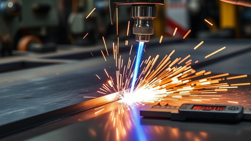
Poor plasma cuts usually have a traceable cause. Heavy dross, a wide kerf, an angled edge, an arc that drops out, or a cut that will not go through can often be tied to air quality, consumable wear, work-clamp contact, torch setup, travel speed, or input power. Work through the checks below in order instead of changing several settings at once.
Quick Answer
To fix poor plasma cuts, first confirm clean, dry air at the pressure and flow listed in your machine manual. Then inspect the consumables, clean and reposition the work clamp, verify input power, and adjust torch height and travel speed. Test each change on scrap so you can identify the real cause.
Key Takeaways
- Air pressure alone is not enough; the compressor must also supply the required airflow while the torch is flowing.
- Use the exact consumables, amperage, gas, cut speed, and standoff listed for your machine and material.
- A clean, tight work-clamp connection close to the cut is essential for a stable transferred arc.
- Low-speed dross, high-speed dross, bevel, and incomplete cuts point to different setup problems.
- Do not open the power supply, splice a torch lead, or probe live circuits unless you are a qualified service technician.
At a Glance
| Time Required | 10–30 minutes for basic checks; longer if a filter, lead, or electrical service needs repair |
| Difficulty | Beginner for external checks; professional service for internal electrical or torch-lead faults |
| Tools Needed | Machine manual, clean scrap metal, air gauge or built-in gas test, clean rag, abrasive pad, and replacement consumables |
| Cost | Often $0 for setup corrections; filters and consumables commonly add a modest parts cost; electrical or torch repairs cost more |
Warning: Plasma cutting exposes you to intense light, hot metal, sparks, fumes, pressurized gas, and dangerous voltage. Wear the eye and face protection specified for the arc current, use flame-resistant clothing and gloves, provide effective ventilation and hot-work fire controls, remove combustibles, and never cut a sealed or previously used container unless it has been properly cleaned, vented, and tested. Disconnect input power before external maintenance, and leave internal repairs to qualified personnel.
How to Diagnose Poor Plasma Cuts
Start with the symptom you can see. The table below points to the first checks that are most likely to help. Several variables can create the same defect, so change one item at a time and make a short test cut after each change.
| Cut symptom | Likely causes | First checks |
|---|---|---|
| Thick, bubbly dross | Travel speed too slow, amperage too high, or torch too close | Increase speed slightly and verify the cut chart settings |
| Small, hard bead of dross | Travel speed too fast, amperage too low, or torch too high | Slow down slightly and check standoff and consumable rating |
| Cut does not go through | Low airflow, excessive speed, worn consumables, low input power, or material beyond capacity | Check gas flow, power, consumables, and rated cut capacity |
| Wide kerf or rounded top edge | Worn nozzle, speed too slow, torch too high, or excessive heat input | Inspect the nozzle and compare speed and height with the cut chart |
| Strong bevel or angled edge | Torch tilted, wrong travel direction, worn nozzle, incorrect height, or hand movement | Hold the torch square, inspect consumables, and use a guide |
| Arc starts, sputters, or goes out | Poor work-clamp contact, unstable gas pressure, damaged torch lead, or power fault | Clean and move the clamp, run a gas test, and check fault indicators |
Note: The machine’s operator manual and cut chart override generic settings. Plasma systems differ in required pressure, flow, consumable design, drag-cutting ability, input power, duty cycle, and rated thickness.
Insufficient Airflow From the Compressor
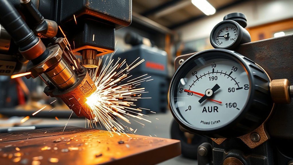
A plasma cutter needs both enough pressure and enough airflow. A gauge may show a healthy static pressure while the pressure drops as soon as the torch begins its gas test or cutting cycle. That drop can weaken the arc, shorten consumable life, and leave rough edges or incomplete cuts.
Check Flow and Pressure Under Load
Find the required inlet pressure and airflow in your operator manual. For example, the Hypertherm Powermax30 XP specifies 4 scfm at 80 psi, while other machines use different values. Do not treat one pressure number as a rule for every plasma cutter.
- Run the machine’s gas-test mode, if available, and read the pressure while air is flowing.
- Confirm the compressor’s delivered CFM or SCFM at the required pressure, not only its tank size or peak pressure.
- Watch for a falling gauge as the tank empties. A small compressor may meet pressure briefly but fail during longer cuts.
- Check whether another tool is drawing from the same air supply.
Remove Airflow Restrictions
A clogged filter, kinked hose, leaking fitting, undersized hose, or long air line can reduce flow at the machine. Inspect the full path from the compressor to the plasma cutter. Use the hose diameter and maximum length listed by the manufacturer.
Clean, dry air delivered at the required pressure and flow is one of the fastest ways to improve cut quality and consumable life.
Low or Unstable Pressure From the Regulator
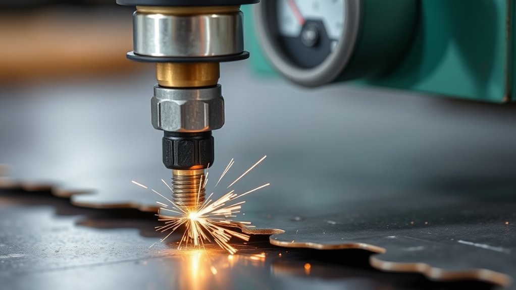
A regulator that is set incorrectly, contaminated, undersized, or failing can cause pressure swings. The result may be a sputtering arc, intermittent cutting, extra dross, or a low-pressure fault.
Products Worth Considering
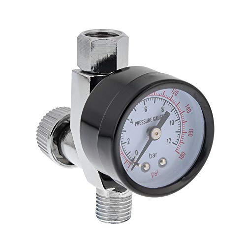
Maintain Optimal Spray Gun Performance: This air adjusting valve regulator ensures your spray guns operate effectively for consistent results.

【Industrial Performance】The air drying system features two rugged 3/4“ NPT air ports and 1/4” NPT gauge ports to handle high-pressure environments (up to 240 PSI) for a variety of industrial applications. Note: To prevent air leakage, please wrap the sealing tape around the threads appropriately before connecting the screws.

High Pressure Tolerance – The air drying system features 1/2" NPT air ports and 1/4" NPT gauge port, capable of handling 0-240 PSI pressure range with 141 CFM (4000L/min) flow rate, ideal for industrial applications like paint spray and plasma cutters. Aluminum alloy body with corrosion-resistant metal bowls ensures endurance in harsh industrial environments
Common Causes of Low Pressure
- The compressor cannot maintain the required flow.
- The regulator is adjusted while no air is moving, so the dynamic pressure is lower during cutting.
- The filter element is dirty or the bowl contains water or oil.
- A hose is too small, too long, kinked, or leaking.
- Another air tool is using the same line.
- The regulator, solenoid, or internal valve needs service.
How to Adjust the Regulator Correctly
- Set the machine to gas-test or purge mode, if the manufacturer provides one.
- Adjust the regulator while gas is flowing.
- Set it to the exact range in the operator manual.
- Watch the reading for several seconds. A large drop or repeated swing points to a supply, filter, hose, or regulator problem.
- Return automatic-pressure systems to their normal mode after testing.
Do not disassemble a pressurized regulator or internal valve unless the manual specifically authorizes that work. Release air pressure and disconnect power before external service.
Electrical Interference and Equipment Setup
Electromagnetic interference can affect mechanized plasma systems, CNC controls, height controls, and nearby electronics. For a handheld cutter, however, low input voltage, a weak work connection, damaged cables, and blocked ventilation are usually more useful first checks than adding improvised shielding.
Equipment Location and Setup
- Place the power supply on a stable, dry surface with the ventilation clearance listed in the manual.
- Keep torch leads, work leads, control cables, and sensitive signal cables routed as the manufacturer directs.
- Do not coil excess power or torch cable tightly around the machine while cutting.
- For CNC systems, follow the plasma and table manufacturer’s bonding, shielding, and cable-separation plan.
- Keep the unit away from rain, standing water, grinding dust, and direct hot-spark paths.
Protective Grounding and EMI Control
The plasma power supply must be connected to a correctly wired protective earth through its power cord. The work clamp serves a different purpose: it completes the cutting circuit. Do not confuse the work lead with the electrical safety ground.
Use the correct grounded receptacle, cable, and circuit for the machine. Do not build a metal enclosure around the power supply or alter grounding conductors. For persistent EMI on a mechanized table, use the manufacturer’s grounding and shielding guide or a qualified controls technician.
Voltage Drop and Undersized Electrical Service
An undersized circuit, long extension cord, damaged cord, loose plug, or weak generator can reduce the voltage reaching the plasma cutter. That can limit cut capacity, make the arc drop out, trip a breaker, or cause the machine to overheat sooner.
- Use the input voltage, breaker or fuse size, phase, and conductor size listed on the data plate and in the operator manual.
- Avoid an extension cord when possible. When one is required, use the manufacturer’s minimum wire gauge for its length and input voltage.
- Do not share the circuit with a large compressor, welder, heater, or motor unless the electrical system was designed for the combined load.
- Use a generator only when it meets the plasma cutter’s continuous and transient power requirements.
- Have a licensed electrician investigate hot plugs, repeated breaker trips, visible arcing, or suspected low line voltage.
Note: There is no universal “10% voltage-drop” cutoff for all plasma cutters. Use the input-voltage tolerance and cord table for your exact model.
Worn, Damaged, or Incorrect Consumables
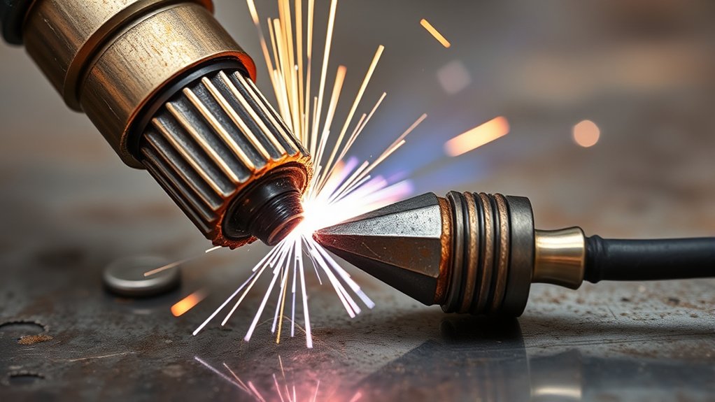
Consumable wear changes the shape and energy of the plasma arc. A damaged nozzle can widen the kerf and increase bevel. A worn electrode, blocked shield, damaged swirl component, dirty O-ring, or mismatched part can cause hard starts, unstable cutting, or short consumable life.
Products Worth Considering

[Achieve Precise Cuts] PT31 Plasma Cutting Consumables – Your Essential Tool for Efficient Cutting! Whether you're working with sheet metal, steel, or any other material, superior cutting performance ensure clean, accurate, and smooth cuts.

PACKAGE INCLUDED: 5 Pcs Cup-15 Pcs Electrodes-10 Pcs Ring-30 Pcs Tip(Standard)
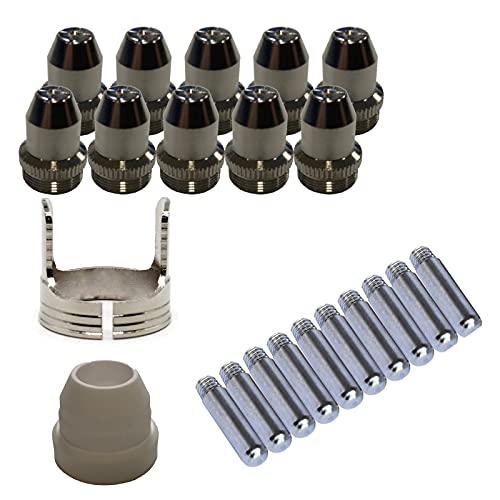
Only Compatible with BROWN Color Lotos LTP5800D , LTP5000D, LTPDC2000D.
Signs of Consumable Wear
- The nozzle orifice is oval, enlarged, nicked, burned, or coated with spatter.
- The electrode has reached the wear limit stated by the manufacturer.
- Air holes in the shield or cartridge are blocked.
- The O-ring is cut, dry, swollen, or contaminated.
- Cut quality changes suddenly even though speed, height, and material are unchanged.
- The arc starts inconsistently or sounds rough.
Replacement Guidelines
Use the inspection method and wear limit for your exact torch. A single pit-depth number does not apply to every electrode or cartridge. Some modern torches use a one-piece cartridge that should be replaced as a unit rather than disassembled.
- Install genuine or manufacturer-approved parts that match the torch, process, gas, and selected amperage.
- Keep hands, parts, and sealing surfaces clean during assembly.
- Do not use tools to force consumables together unless the manual calls for them.
- Replace a visibly damaged nozzle or shield before it damages the torch body.
- Track starts or arc-on time if you need predictable consumable life in production work.
Impact on Performance
Worn consumables can cause wider kerfs, excessive bevel, heavy dross, top spatter, incomplete cuts, and wandering arcs. If a fresh, correctly installed consumable set fixes the problem, inspect the old parts to learn which failure pattern caused the change.
Pro Tip: Keep one known-good consumable set for troubleshooting. It helps separate a consumable problem from an air, power, or technique problem without replacing several unrelated parts.
Damaged Torch Lead or Open Circuit
A torch lead can fail after repeated bending, crushing, heat exposure, tight cable ties, or damage at the connector. Depending on the design, the lead may carry gas, trigger conductors, pilot-arc current, communication wiring, and high cutting current.
Warning: Do not splice a torch lead, probe internal conductors, or perform continuity tests on a connected machine. Turn the power supply off, unplug it, release gas pressure, and follow the manual. A damaged lead or torch body should be replaced or serviced by a qualified technician.
| External finding | Safe response |
|---|---|
| Loose quick-connect fitting | Reconnect it fully with the machine off |
| Kink, crushed area, cut jacket, exposed conductor, or gas leak | Stop using the machine and arrange approved replacement or service |
| Bent or damaged connector pins | Do not straighten live or delicate contacts; use an authorized repair facility |
| No visible damage but repeated torch or communication fault | Record the fault code and contact technical support |
Incorrect Cutting Speed and Torch Angle
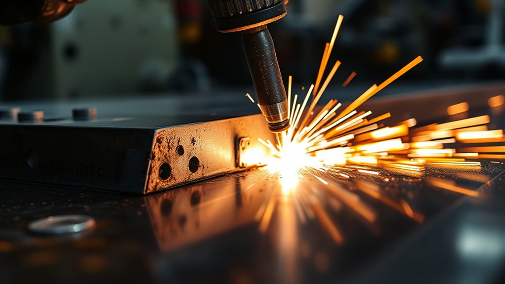
Travel speed is one of the biggest cut-quality controls. Hypertherm identifies speed, amperage, and standoff as three critical dross variables. The correct speed lets the plasma jet pass through the plate and eject molten metal from the kerf.
Read the Dross Pattern
- Low-speed dross: Thick, bubbly deposits along the bottom edge. Increase speed in small steps, or check for excessive amperage or low standoff.
- High-speed dross: A narrow, hard bead that is difficult to remove. Slow down slightly, or check for low amperage or excessive standoff.
- Top spatter: Molten metal collects on the top edge. Check speed, torch height, pierce height, and nozzle condition.
Hold the Torch Square
Keep the torch close to 90 degrees to the workpiece for a square cut. A tilted torch produces an angled edge. Relax your grip and use a straightedge, roller guide, or circle guide when hand movement is the problem.
Use Sparks as a Speed Clue
During a through-cut, sparks should pass through the plate and trail slightly behind the torch. Sparks spraying straight back at you or across the top often mean the arc is not fully penetrating. Slow down, confirm air and power, or check whether the material is beyond the machine’s rated capacity.
Material grade, surface coating, flatness, and plate temperature also affect dross. Compare test cuts on similar clean material before assuming the machine has a fault, and use proper fume controls when cutting coated or galvanized metal.
Poor Work-Clamp Contact
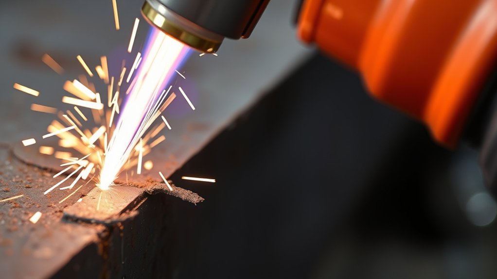
The work clamp completes the cutting circuit. Paint, rust, scale, oil, loose jaws, a damaged lead, or clamping to the drop piece can make the transferred arc unstable.
- Remove rust, paint, coatings, and dirt where the clamp contacts the metal.
- Attach the clamp to the workpiece or cutting table as the manufacturer directs.
- Place it as close to the cut as practical without putting it on the piece that will fall away.
- Inspect the clamp jaws, spring, cable, and connector for heat damage or looseness.
- Use a work lead approved for the machine’s amperage, length, and connector.
| Issue | Likely cause | Correction |
|---|---|---|
| Arc sputters or drops out | Loose or dirty clamp contact | Clean to bare metal and reposition the clamp |
| Clamp or connector gets hot | High resistance, loose connection, or undersized lead | Stop cutting and repair or replace the approved component |
| Cut stops near the end | Clamp attached to the section being cut away | Move it to the retained workpiece |
Wrong Torch Height, Standoff, or Pierce Height

The correct torch-to-work distance depends on the torch, shield, consumables, amperage, and process. Some handheld systems are designed for drag cutting. Others require a standoff, often around 1/8 inch for a specific setup. Mechanized systems use cut height and pierce height from a cut chart.
- Too high: The arc stretches, the kerf widens, bevel can increase, and the cut may not go through.
- Too low: The nozzle or shield can contact spatter, overheat, double-arc, or wear early.
- Uneven height: A warped plate or unsteady hand creates changing bevel and kerf width.
- Piercing too low: Molten metal blows back into the nozzle and shield.
For systems that use a separate pierce height, Hypertherm gives a general recommendation of about 1.5 to 2 times the recommended cut height. That is not the same as “twice the nozzle size,” and the machine’s cut chart still takes priority.
Pro Tip: Mark a short test line on scrap and hold a steady standoff with a guide. If the cut improves, the issue was technique or height rather than the power supply.
Cooling Fan, Duty Cycle, and Ventilation
A plasma cutter that overheats may reduce output, stop the arc, show a temperature fault, or trip a breaker. The fan does not run continuously on every model, so silence alone does not prove that the fan has failed.
- Keep the intake and exhaust louvers clear of dust, walls, covers, and stored items.
- Use the clearance listed in the manual; one current Hypertherm manual calls for about 10 inches around the power supply.
- Do not exceed the rated duty cycle. Duty cycle is the allowed arc-on time within a stated interval, usually at a stated ambient temperature.
- If a temperature fault occurs, follow the manual. Some systems should remain powered on so the fan can cool the unit.
- Do not remove panels to clean or test an internal fan unless you are qualified and the service procedure authorizes it.
Dust buildup, blocked vents, high ambient temperature, low input power, and long arc stretching can all make overheating happen sooner.
Air-Path Blockage or Contamination

Water, oil, vapor, dirt, and rust particles can damage internal components and shorten consumable life. Contamination may also block a filter, regulator, valve, torch passage, or shield opening.
Common Sources of Obstruction
- A saturated compressor filter or water separator
- Condensate in the tank or air line
- Oil carryover from the compressor
- Undersized fittings or restrictive quick couplers
- A kinked or crushed hose
- Debris in the machine’s filter element
- Spatter blocking shield or cartridge airflow holes
How Contamination Affects Performance
Dirty or wet gas can cause hard starting, unstable pressure, rough cuts, lower cut speed, reduced thickness capacity, and shorter consumable life. Drain the compressor tank, service external filters, and inspect the machine’s filter bowl as directed by the manual. Add suitable filtration or drying if moisture or oil keeps reaching the machine.
Internal solenoid or valve service is not routine operator maintenance. If external filtration, pressure, and hose checks are good but the fault remains, contact the manufacturer or an authorized repair facility.
Weak Plasma Arc or Incomplete Cut
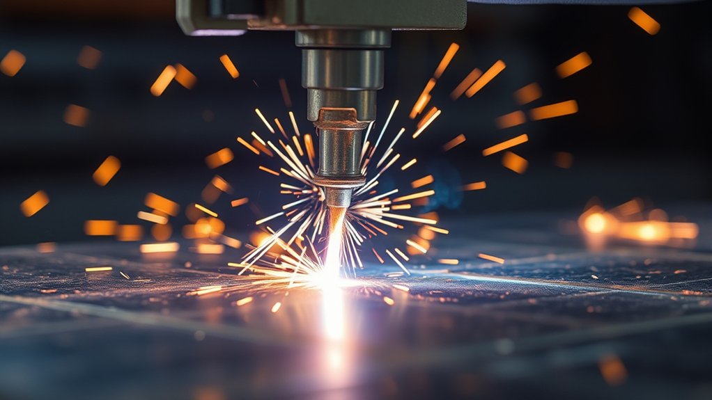
A weak arc is usually a symptom, not a single failure. Work through the causes in this order:
- Material and capacity: Confirm the metal type and thickness are within the machine’s recommended cut range, not only its severance limit.
- Consumables: Install the correct, undamaged parts for the selected amperage and process.
- Air: Check clean, dry gas, dynamic pressure, required flow, leaks, and hose size.
- Work connection: Move the clamp to clean bare metal close to the cut.
- Input power: Remove an undersized extension cord and confirm the correct circuit or generator.
- Technique: Reduce excessive travel speed, maintain the correct height, and avoid stretching the arc.
- Heat: Let the machine recover if it has reached its duty-cycle or temperature limit.
Excessive gas pressure can also cause hard starting and rapid electrode wear. Set pressure to the manufacturer’s range rather than assuming that more pressure creates a stronger arc.
Wrong Amperage or Consumable Rating
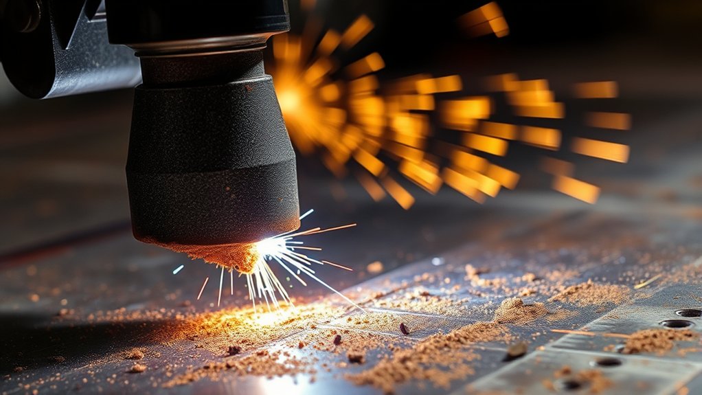
A nozzle or cartridge is designed for a stated current range. Exceeding that rating can overheat and damage it, but an arbitrary rule such as staying below 95% of the rating is not needed. A 100-amp consumable is normally intended to run at 100 amps when the manufacturer’s chart calls for it.
| Setup error | Possible result | Correction |
|---|---|---|
| Current above consumable rating | Rapid wear, overheating, nozzle damage, poor arc shape | Install the consumable rated for the selected current |
| High-current nozzle used at much lower current | Poor arc constriction or lower cut quality on some systems | Use the nozzle or cartridge specified for that amperage |
| Wrong shield, swirl component, or gas | Hard starts, bevel, dross, or damaged parts | Match the complete stack to the parts chart |
Set amperage, speed, height, and consumables as one matched process. Changing only amperage without checking the rest of the cut chart can create a new defect.
Pilot Arc, Fuse, and No-Start Problems
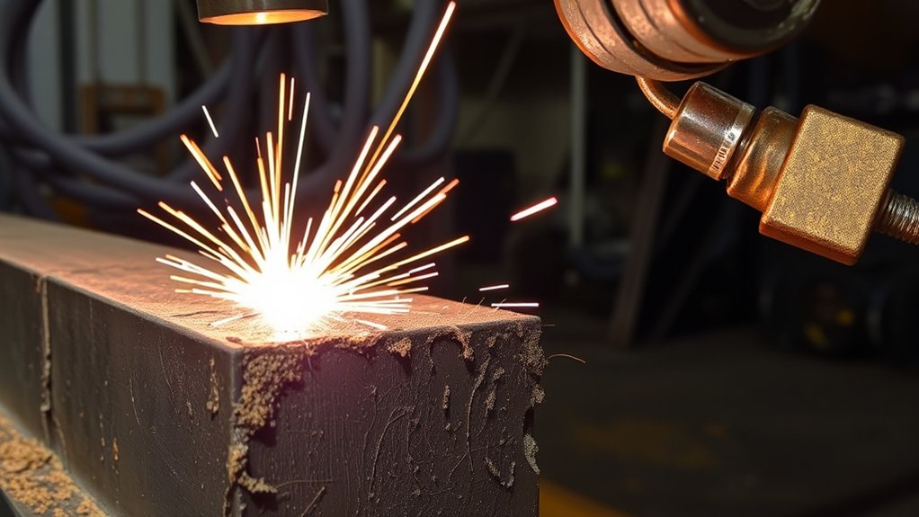
A plasma cutter that will not fire may have a simple setup fault, a pressure fault, an incorrectly installed consumable, a locked torch, a damaged lead, or an electrical problem. There is no universal 15-amp fuse that applies to every machine.
Safe No-Start Checklist
- Read the display, fault lights, or fault code before cycling power.
- Confirm the torch lock and trigger safety are in the correct operating position.
- Turn the machine off and verify that the consumables are the correct parts and fully seated.
- Check the gas connection, dynamic pressure, and filter condition.
- Inspect the torch lead and quick-connect fitting externally for damage.
- Clean and attach the work clamp correctly. Some pilot arcs can start without the workpiece, but the main transferred cutting arc needs a complete work circuit.
- Check the branch-circuit breaker or external fuse specified for the machine.
- If the manual identifies a user-serviceable fuse, replace it only with the exact type and rating stated by the manufacturer.
If a fuse opens again, the torch communication fault remains, or internal testing is required, stop troubleshooting and use qualified service. Repeatedly installing a larger fuse can create a fire or shock hazard.
Air Supply and Regulator Final Check
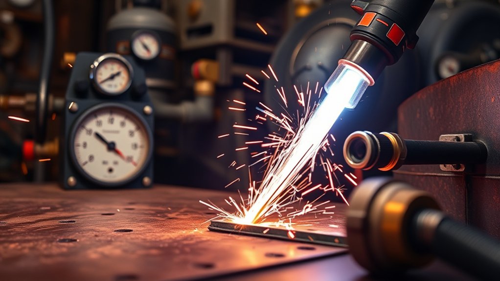
Air problems appear in several forms, so use this final check before blaming the power supply:
- Drain the compressor tank and external water separator.
- Confirm the compressor can deliver the required flow at the required pressure.
- Run gas-test mode and adjust pressure while gas is flowing.
- Listen and test for leaks at fittings and hoses.
- Check hose length, inside diameter, kinks, and restrictive couplers.
- Inspect or replace external filters and the machine filter element as directed.
- Look for oil, water, or dirt in the filter bowl and air line.
- Make a test cut on clean scrap using the exact cut-chart settings.
If pressure stays steady and clean, dry air reaches the machine, move to consumables, work-clamp contact, input power, and torch technique.
Maintenance Schedule for Clean Plasma Cuts
| Interval | Checks |
|---|---|
| Before each use | Inspect consumables, torch lead, work lead, clamp, power cord, gas hose, vents, and fault indicators. Confirm settings against the cut chart. |
| Daily or after heavy use | Drain compressor moisture, clean spatter from approved external torch parts, and check the filter bowl. |
| Weekly | Check fittings for leaks, clean vents externally, inspect clamp jaws and connectors, and review consumable wear. |
| As specified by the manual | Replace filter elements, O-rings, damaged leads, or other service parts at the listed interval or condition. |
Frequently Asked Questions
How does torch alignment affect plasma cutting quality?
A torch that is not square to the plate creates an angled cut face. Hold a hand torch close to 90 degrees, keep its height steady, and use a guide when needed. If bevel remains on every side, inspect the nozzle and verify the cut height and speed.
What role does cooling play in preventing material warp during cuts?
Warp comes from uneven heat input. Use the correct speed and amperage, plan the cut order, leave tabs when needed, support thin sheet, and allow parts to cool between nearby cuts. Do not spray water on electrical equipment or use water-cutting methods unless the system is designed for them.
How can worn consumables lead to interrupted cuts?
A worn electrode or damaged nozzle can make the arc unstable, change gas flow, or prevent a reliable transfer to the workpiece. Inspect the complete consumable stack, replace parts at the manufacturer’s wear limit, and make sure the correct parts are clean and fully seated.
Why does high speed reduce plasma-cut hole quality?
Excess speed makes the arc lag and can leave bevel, an out-of-round hole, or a hard dross bead. Hole quality also depends on pierce height, lead-in, torch height, consumables, and hole diameter. Use the machine’s hole-cutting recommendations or slow the path only as the manufacturer directs.
How important is regular maintenance for good plasma cuts?
Regular maintenance keeps air clean, connections tight, cooling passages open, and consumables within their wear limits. A short pre-use inspection often catches the cause of poor cuts before it damages the torch or ruins a workpiece.
What air pressure should a plasma cutter use?
Use the pressure and airflow specified for the exact model, measured while gas is flowing. There is no universal minimum. Also confirm the compressor can maintain the required CFM or SCFM and that filters, hoses, and fittings are not causing a pressure drop.
Why is my plasma cut angled even when I hold the torch straight?
Check for an oval or damaged nozzle, incorrect standoff, excessive speed, worn torch parts, and the direction of travel. Plasma produces a good side and a scrap side because the gas swirls in the torch, so orient the cut path as the manufacturer recommends.
Sources
- Hypertherm: Troubleshooting Excess Dross — backs the relationships among speed, amperage, standoff, and dross type.
- Hypertherm: 10 Common Plasma Cutting Mistakes — backs consumable inspection, clean gas, pierce height, speed, and arc-stretch guidance.
- Hypertherm Powermax45 SYNC Operator Manual — backs air quality, hose sizing, extension-cord sizing, work-clamp placement, ventilation, duty cycle, and qualified-service warnings.
- Miller: Hand-Held Plasma Cutter Guide — backs pre-cut checks, clamp placement, typical standoff, torch control, and spark-direction guidance.
- OSHA 29 CFR 1910.133: Eye and Face Protection — backs eye and face protection for plasma arc cutting and other radiant-energy hazards.
- OSHA 29 CFR 1910.252: Welding, Cutting, and Brazing — backs fire prevention, ventilation, and precautions for containers and coated metals.
Conclusion
The best way to fix poor plasma cuts is to troubleshoot in a set order: identify the defect, verify clean and steady air, inspect the correct consumables, improve work-clamp contact, confirm input power and cooling, then tune height and speed on scrap. Avoid universal pressure, fuse, wear-limit, and standoff rules when your machine’s manual gives model-specific values. If the torch lead, internal valve, fan, or power supply needs electrical testing, stop and use qualified service.