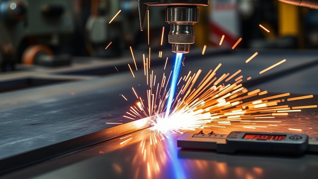
Plasma cutting can produce clean, repeatable metal parts, but the process does not have one universal tolerance. A handheld torch, an entry-level CNC table, and a high-definition industrial system deliver very different results. The final dimension also depends on the table, torch height, cut speed, kerf compensation, consumables, material, and measuring method.
Quick Answer
Plasma cutting is typically accurate to about ±1.6 mm (±1/16 in.) by hand, around ±0.77 mm (±0.030 in.) on entry-level CNC tables, and roughly ±0.25 to ±0.51 mm (±0.010 to ±0.020 in.) on well-configured industrial systems. Actual part accuracy depends on the complete machine, material, programming, consumables, and setup.
Key Takeaways
- A published tolerance is a starting point, not a guarantee for every table, thickness, shape, or material.
- Handheld plasma is useful for repair and fabrication, but a guide or template is needed for its best repeatability.
- CNC table motion, torch height control, kerf compensation, cut direction, and lead-ins can matter as much as the plasma source.
- Too-fast and too-slow travel create different defects, so use the manufacturer’s cut chart before making small adjustments.
- Measure test coupons after they cool before approving a plasma process for close-fitting or high-tolerance parts.
At a Glance
| Time Required | About 15–30 minutes to set up, cut, cool, and measure a basic test coupon |
| Difficulty | Beginner for handheld guide cuts; intermediate for CNC tuning and dimensional checks |
| Tools Needed | Plasma cutter, correct consumables, scrap material, straightedge or CNC table, calipers, square, and PPE |
| Cost | Usually only the cost of scrap and consumable wear if measuring tools are already available |
What Plasma Cutting Accuracy Really Means
Accuracy is the difference between the programmed or marked dimension and the dimension you measure on the finished part. Repeatability is the machine’s ability to make the same result several times. Cut quality covers other features, including edge angle, dross, surface finish, kerf width, and hole roundness.
These terms are related, but they are not interchangeable. A table can return to the same position accurately while the finished part is still undersized because the kerf compensation is wrong. A part can also measure correctly at the top edge while having enough bevel that the bottom edge is outside tolerance.
- Dimensional accuracy: How close the finished length, width, or diameter is to the drawing.
- Repeatability: How closely several copies match one another.
- Kerf: The width of material removed by the plasma arc.
- Cut angularity: The difference between the top and bottom dimensions caused by a tapered edge.
- Heat distortion: Movement or bowing caused by uneven heating and cooling.
The plasma source is only one part of the accuracy chain. The table, motion controls, torch height, programming, material, and inspection method all affect the finished dimension.
Plasma Cutting Processes and Their Tolerances
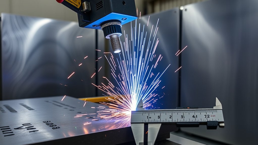
Plasma cutting accuracy changes from one system to another. Each process gives you a different balance of speed, cost, edge quality, and tolerance. The ranges below are practical expectations reported by Hypertherm’s plasma accuracy guidance, not guaranteed specifications for every machine.
| Plasma process | Typical dimensional expectation | Best fit |
| Skilled handheld cutting | About ±1.6 mm (±1/16 in.) with a steady operator and a guide | Repairs, field work, rough fabrication, and artwork |
| Entry-level CNC plasma | About ±0.77 mm (±0.030 in.) | Signs, brackets, hobby parts, and general shop work |
| Light-industrial CNC plasma | About ±0.38 to ±0.64 mm (±0.015 to ±0.025 in.) with capable height control and motion | Small production runs and parts needing less cleanup |
| Heavy-industrial or advanced high-definition plasma | About ±0.25 to ±0.51 mm (±0.010 to ±0.020 in.), depending on material, thickness, table, and process | Repeat production, cleaner edges, and closer-fitting fabricated parts |
High-definition and X-Definition systems can provide the best precision in this group. On a high-quality cutting machine, some advanced systems can meet ISO 9013 tolerance classes and produce cut quality in the tighter ISO ranges, but the result still depends on the complete installation and the selected process. Hypertherm explains this distinction in its comparison of advanced plasma and fiber laser cutting.
Note: Do not treat a general tolerance range as a machine guarantee. Ask for cut samples made from your material and thickness, then measure the complete part at both the top and bottom edges.
Handheld Plasma Cutting: Achieving Better Precision
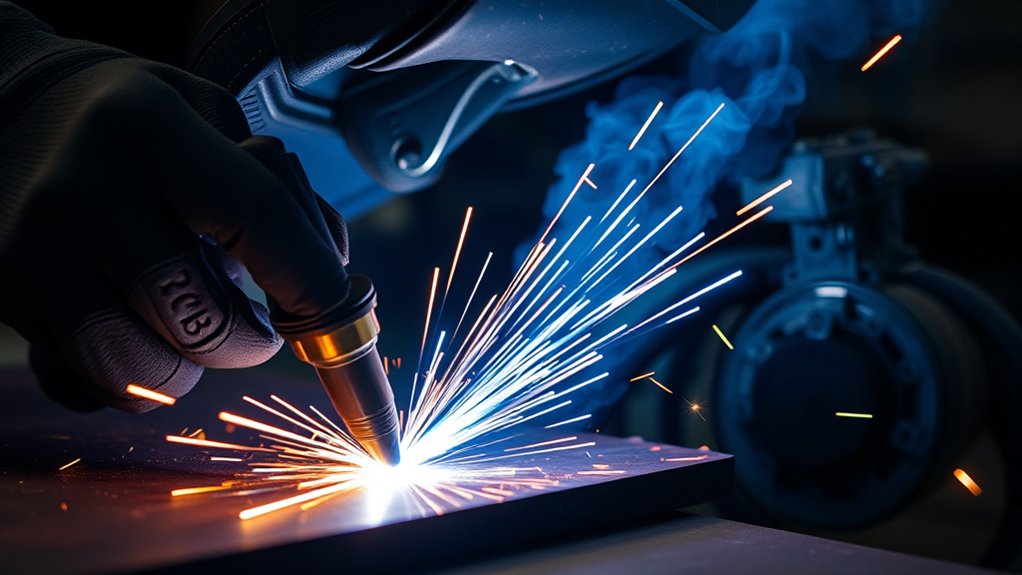
Handheld plasma cutting gives you flexibility, but it relies on your control. A skilled operator can often hold a tolerance of about 1.6 millimeters (1/16 inch), but results vary from cut to cut. Freehand cutting is normally less consistent than cutting against a guide.
Your hand speed, standoff distance, torch angle, body position, and view of the cut line all affect the result. Steady movement helps reduce bevel, dross, and rough edges. A drag shield can also help maintain the intended standoff when the torch and consumables are designed for drag cutting.
Handheld systems cannot match CNC machines for repeatability. They still work well for repair work, rough fabrication, field cutting, and artistic metalwork where some variation fits the job.
Pro Tip: Clamp a straightedge, circle guide, or rigid template far enough from the cut line to account for the torch body and kerf. Make a short test cut before cutting the finished piece.
Products Worth Considering

STRAIGHT EDGE - Jackson Safety's #28 Magnetic Burning Guide provides a strong, durable straight edge while using a burning torch or plasma cutter


Holds straight edge or Plasma Stencil where a clamp won't reach
CNC Plasma Cutting Machines: Entry-Level to Heavy-Industrial Systems
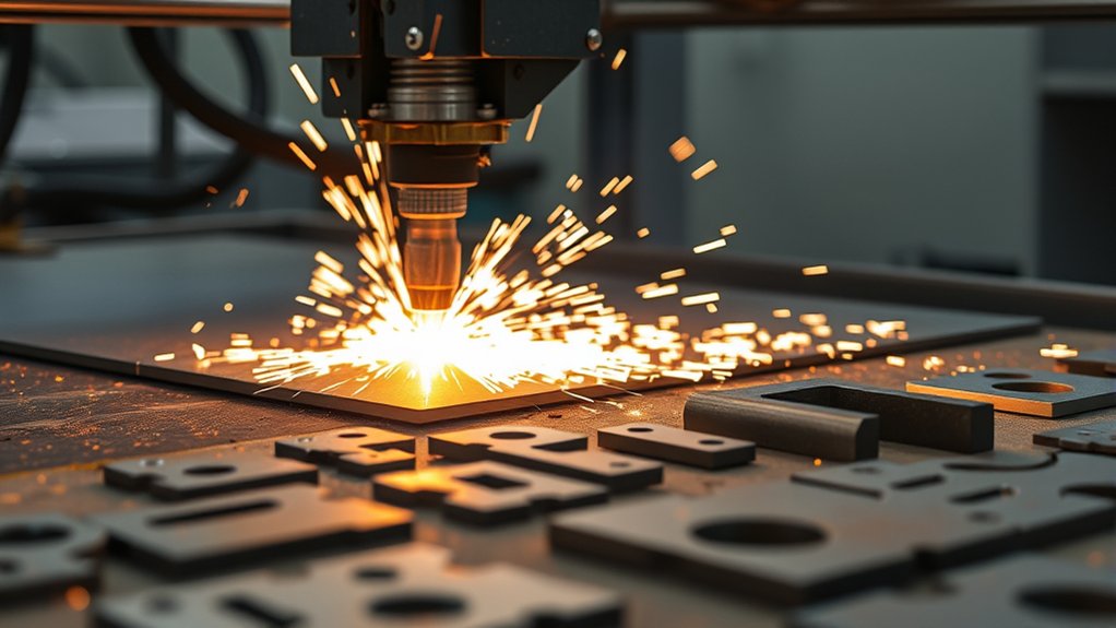
CNC plasma cutting machines range from small hobby tables to heavy-industrial production systems. Your tolerance depends on the table, motion control, torch height control, plasma source, software settings, and how well those components work together.
Entry-level machines often hold tolerances near ±0.77 millimeters. That level suits signs, brackets, shop projects, and parts that do not need machining-level accuracy.
Typical published expectations are about ±0.77 mm for entry-level CNC plasma and about ±0.38 to ±0.64 mm for better-controlled light-industrial systems.
Light-industrial CNC burn tables offer better rigidity and smoother motion. They work well for small shops, short production runs, and parts that need cleaner edges.
Heavy-industrial plasma cutters can reach about ±0.25 to ±0.51 millimeters, depending on material thickness and setup. Automated torch height control improves accuracy because it helps keep the torch at the intended cut height as the plate moves and consumables wear.
High-definition systems improve cut quality even more. They work best when you need repeatable parts, smaller holes, cleaner edges, and less cleanup.
Products Worth Considering

ALL-IN-ONE HI-END TECHNOLOGY PLASMA CUTTING MACHINE SET: Redefine your metal crafting experience with the Eastwood Versa Cut 4X4 CNC Plasma Table and Plasma Cutting Machine Torch Set. Crafted for those who demand perfection and a user-friendly metal fabrication experience. This all-in-one powerhouse brings a new level of control and versatility to your workshop or home garage. A fusion of precision, efficiency, and cutting-edge technology in one bundle.

CNC Function: The STC850P MAX plasma cutter machine is equipped with blowback technology and Non-HF (non-high frequency) pilot arc, which are compatible with CNC systems. This setup minimizes the risk of high-frequency signal interference, thereby improving cutting stability. The non-touch blow-back pilot arc initiation ensures that the arc starts without the need for physical contact with the metal. The plasma cutter features two connection ports: a 2-pin connector for arc voltage output at 1:1 ratio and 5-pin connector for signal control. This design facilitates seamless integration with CNC cutting tables

【Powerful Cutting Ability】Dual voltage plasma cutter 110 220 operation is perfect for home garages, workshops, and hardware shops. Delivers professional performance 1/2" clean cuts on iron, steel, aluminum and copper using Inverter IGBT Technology. Suitable for both DIY and heavy-duty projects. Maximum recommended cutting thickness: 1/2" @ 35A 110V 50 PSI; 2/3" @ 50A 220V 65 PSI. Requires dry, compressed air. Recommended power breakers: 40A @ 110V; 30A @ 220V.
Machine Motion and Programming Factors
- Backlash and loose drive parts: Play in gears, racks, belts, or bearings can change dimensions and make circles out of round.
- Table squareness: A 100 mm square may have correct side lengths but unequal diagonals when the gantry is not square.
- Torch height control: A torch that runs too high can increase kerf width and positive bevel; a torch that runs too low can create negative bevel or collide with the plate.
- Kerf compensation: The CAM software must offset the toolpath by the correct amount for the consumables, amperage, gas, and material.
- Lead-ins and lead-outs: Poor placement can leave divots, oversized entry points, or distorted holes.
- Acceleration and cornering: A table that slows sharply at corners can add heat and change kerf width unless the process and software account for it.
Factors That Affect Plasma Cutting Accuracy
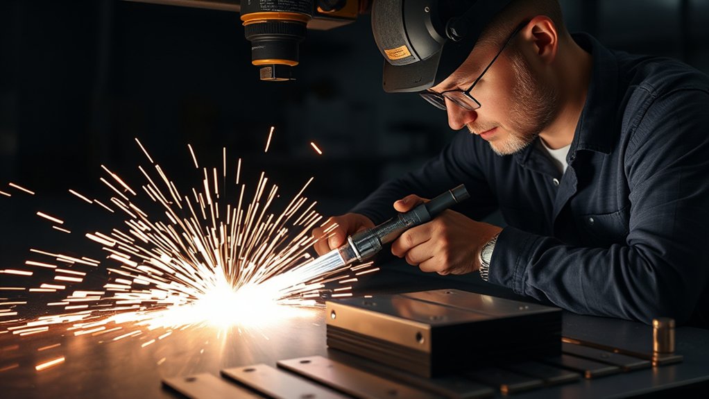
You can improve plasma cutting accuracy when you control the main process variables. The biggest factors include speed, torch height, material thickness, amperage, air or gas quality, consumable wear, cut direction, workholding, and table condition.
- Cutting speed: Traveling too fast can cause arc lag, a narrow or unstable kerf, bevel, and high-speed dross. Traveling too slowly can widen the kerf, add heat, round the top edge, and create low-speed dross.
- Torch height: Incorrect standoff can create bevel, poor arc control, a changing kerf, and uneven dimensions.
- Material thickness: Thick plate needs enough power and controlled speed, while thin sheet can move or warp from heat.
- Consumable condition: Worn nozzles and electrodes can shift the arc, change kerf width, increase angularity, and reduce repeatability.
- Air or gas quality: Moisture, oil, poor pressure, or the wrong gas can shorten consumable life and make the arc less stable.
- Operator and programmer skill: Correct setup, cut charts, maintenance, nesting, and inspection help the system work near its practical capability.
Slower is not always more accurate. The correct speed keeps the arc attached through the plate without excessive lag or heat buildup. Use the cut chart for your exact system, material, thickness, amperage, and consumables, then make small changes only after inspecting the cut.
Good operators inspect the torch, nozzle, electrode, shield, ground clamp, cables, air supply, plate support, and table motion before accuracy problems appear. Hypertherm’s CNC plasma cut-quality checklist also emphasizes cut direction, the correct process, consumable wear, torch squareness, torch-to-work distance, and speed.
Comparing Plasma Cutting Accuracy Across Different Metals
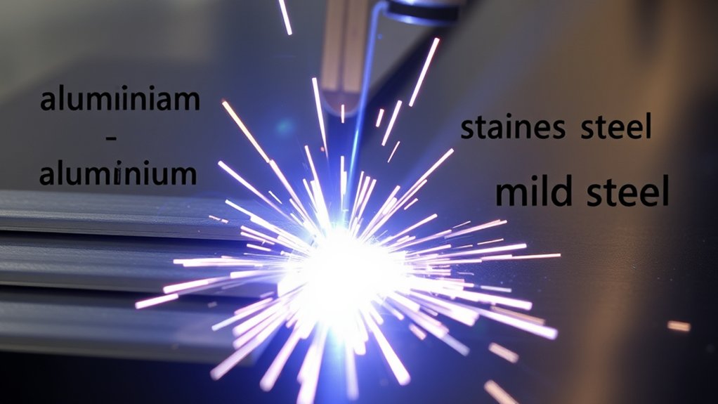
Metal type affects plasma cutting accuracy because each material transfers heat, forms an oxide, and responds to the plasma gas differently. Aluminum, stainless steel, and mild steel can all cut well, but they should not be assigned one fixed tolerance based only on the alloy name.
- Mild steel: It has the broadest range of optimized air, oxygen, high-definition, and advanced mechanized processes. Published best-case plasma tolerances are often demonstrated on mild steel.
- Stainless steel: Gas selection, thickness, alloy, and process affect edge color, dross, angularity, and surface chemistry. Use the manufacturer’s stainless cut chart rather than copying mild-steel settings.
- Aluminum: Its high thermal conductivity and low stiffness in thin sheet can make heat distortion and movement more noticeable. Stable support and the correct process are important.
Very thin sheet can bow or move as it heats. Thick plate can remain flatter but may show more edge taper if the amperage, speed, or torch height is not correct. Neither thin nor thick material is automatically more accurate.
To improve results across different metals, match the amperage and consumables to the thickness, control heat input, use the specified gas or clean dry air, clamp or support the work, and run a measured test cut before production.
Note: Coatings, paint, plating, and unknown surface contamination can create hazardous fumes. Remove coatings only with a safe method and use ventilation appropriate for the material.
How Plasma Cutting Accuracy Compares With Other Cutting Methods
Plasma cutting gives you fast, cost-effective cuts on electrically conductive metals. It works well for fabrication, repair, signs, brackets, frames, and production parts that do not need a machined edge.
| Method | Accuracy and edge profile | Best use |
| Plasma | Fast and practical; advanced systems can hold close fabricated-part tolerances, but kerf, bevel, dross, and heat must be managed | Conductive metal from sheet through plate, especially when speed and operating cost matter |
| Laser | Narrow kerf and high precision, especially on thinner sheet and fine features; still creates a heat-affected zone | High-volume sheet-metal parts, fine details, and small holes within the machine’s material range |
| Abrasive waterjet | Often holds tighter tolerances than plasma and is a cold-cutting process, but taper and stream lag still require compensation | Heat-sensitive parts, thick material, and metals or nonmetals that plasma cannot cut |
| Oxyfuel | Wider kerf and larger heat input than plasma, with accuracy that depends heavily on speed, tip condition, and plate thickness | Thick carbon steel where cut speed and fine detail are less important |
Waterjet cutting usually offers tighter tolerances and does not create a heat-affected zone. OMAX reports general abrasive-waterjet tolerances around ±0.003 to ±0.005 inch (about ±0.08 to ±0.13 mm) on suitable systems and applications in its cutting-method comparison. Laser cutting can also provide high precision, especially on thinner sheet metal and small features.
Plasma often wins when you need fast cutting on conductive plate and a tolerance around a few tenths of a millimeter is acceptable. Choose the process based on the required dimension, edge condition, smallest feature, material, heat sensitivity, production rate, and budget.
How to Measure Plasma Cutting Accuracy
Measure the process you actually plan to use. A table-positioning specification does not include kerf, bevel, plate movement, heat distortion, or programming error.
- Create a test coupon. Include a 100 mm square, an outside circle, an inside hole, and at least one slot similar to the finished job.
- Use production settings. Cut the same material, thickness, amperage, consumables, gas, speed, and torch height planned for the real part.
- Cut at least three copies. One accurate part does not prove repeatability.
- Let the parts cool. Hot metal expands, and thin parts may continue to move while cooling.
- Remove only loose dross. Do not grind the measured edges into size.
- Measure several locations. Use calipers or a micrometer appropriate for the tolerance. Measure top and bottom dimensions when bevel matters.
- Check squareness and roundness. Compare both square diagonals and measure holes in at least two directions.
- Record the error. Subtract the programmed dimension from the measured dimension. A consistent offset points to kerf compensation; changing errors point to motion, heat, consumables, or process instability.
Pro Tip: Keep a cut log with material, thickness, consumable part numbers, amperage, gas pressure, cut height, arc voltage, speed, kerf setting, and measured result. It turns future tuning into a repeatable process instead of guesswork.
How to Improve Plasma Cutting Accuracy Step by Step
You can improve accuracy by treating plasma cutting as a controlled process, not just a fast way to cut metal. Start with the manufacturer’s cut chart and change one variable at a time.
1. Select the Correct Cut-Chart Process
Match the material, thickness, amperage, consumables, gas, pierce height, cut height, speed, and arc voltage to the system manual. Do not start with settings copied from a different torch or power source.
2. Inspect and Install the Correct Consumables
Confirm the nozzle, electrode, swirl ring, shield, and retaining cap are the correct parts and are installed properly. Replace worn or damaged parts before using kerf compensation to hide an unstable arc.
3. Supply Clean, Dry Air or the Specified Gas
Drain the compressor, service filters, verify pressure while air is flowing, and check for oil or moisture. Dual-gas and high-definition systems must use the specified gas type, purity, pressure, and flow.
4. Square the Torch and Support the Plate
Check the torch from two directions with a square. Level or support the workpiece so it cannot rock, vibrate, or lift during the cut. Clamp thin material when the setup allows it without blocking the torch path.
5. Set Pierce Height, Cut Height, and Torch Height Control
Use the specified pierce height to protect the nozzle, then move to the correct cut height. Verify the initial-height sensing and torch height control before a detailed nest. Do not use arc voltage alone to correct a mechanical or consumable problem.
6. Tune Speed, Amperage, and Cut Direction
Begin at the cut-chart speed. Reduce speed only when the cut shows clear high-speed symptoms; increase it when excess heat and low-speed dross appear. With standard clockwise-swirl consumables, program outside contours clockwise and inside contours counterclockwise so the squarer side stays on the finished part.
7. Set Kerf Compensation and Lead-Ins
Measure the actual kerf from a stable test cut and enter the correct compensation in the CAM software. Place lead-ins where the pierce mark will not damage the finished edge. Use suitable hole lead-ins and avoid unnecessary lead-outs that cross a finished contour.
8. Run and Measure Test Parts
Cut several coupons, allow them to cool, and measure external dimensions, holes, slots, diagonals, and top-to-bottom taper. Change one setting at a time and keep the result that improves both dimension and cut quality.
Small setup errors can add up quickly. A worn nozzle, loose ground, wet air supply, incorrect kerf value, warped sheet, or loose drive component can turn a capable machine into an inaccurate one.
Plasma Hole Accuracy and Small Features
Holes are harder to cut accurately than outside contours because the table must accelerate, maintain speed, and control the arc over a short path. Small holes may show taper, an entry divot, an oversized top, an undersized bottom, or poor roundness even when outside dimensions are acceptable.
Advanced hole processes can improve this result. For example, Hypertherm states that its specialized True Hole process can produce bolt-ready mild-steel holes down to a 1:1 hole-diameter-to-plate-thickness ratio on supported systems and thicknesses. That capability does not apply to every plasma cutter, material, or program.
- Use the hole process, lead-in, speed, and height specified for the system.
- Keep the torch square and the table motion tight.
- Measure the hole in more than one direction and at the top and bottom.
- Drill, bore, or ream holes when the drawing requires a close fit, precise location, straight wall, or controlled surface finish beyond the verified plasma result.
Troubleshooting Plasma Cutting Accuracy Problems
| Problem | Likely causes | What to check |
| Every outside part is too large or too small | Incorrect kerf compensation or wrong-side offset | Measure actual kerf, verify inside/outside toolpaths, and confirm drawing units |
| Copies vary in size | Loose motion parts, worn consumables, changing torch height, unstable air, or plate movement | Inspect drives and torch, verify pressure under flow, check THC behavior, and secure the plate |
| One edge is more beveled | Wrong cut direction, torch not square, damaged nozzle, or incorrect height | Confirm the good side of the cut, square the torch, inspect consumables, and verify cut height |
| Heavy dross | Speed too fast or too slow, wrong amperage, poor gas, worn parts, or cutting beyond capacity | Identify high-speed versus low-speed dross and return to the cut chart before adjusting |
| Holes are out of round | Backlash, acceleration limits, poor lead-in, excessive speed reduction, or hole too small for the process | Tune table motion, use the supported hole process, and enlarge or machine the feature if needed |
| Thin sheet warps | Excess heat, poor nesting sequence, slow travel, weak support, or long unsupported cuts | Use the correct lower-amperage process, improve support, change the cut sequence, and reduce heat buildup |
Safety Precautions While Tuning a Plasma Cutter
Accuracy testing creates the same arc, fume, electrical, noise, fire, and hot-metal hazards as production cutting. OSHA lists burns, eye damage, electrical shock, ultraviolet radiation, and metal-fume exposure among the hazards of welding and cutting.
Warning: Wear safety glasses with side protection under a plasma-rated face shield or helmet, flame-resistant clothing, dry gloves, and hearing protection. OSHA lists a minimum shade 8 for visible plasma arc cutting below 300 amps; follow the equipment maker’s guidance and never go lighter than the applicable minimum. Use effective ventilation or local exhaust, keep combustibles away, inspect cables and the work lead, avoid wet conditions, and never cut a closed or previously flammable container.
See OSHA’s welding and cutting hazard guidance and eye and face protection standard for workplace requirements. Stainless steel, plated metal, painted parts, and unknown coatings may need additional fume controls based on the material and exposure assessment.
Frequently Asked Questions
How Does Plasma Cutting Compare to Waterjet Cutting in Terms of Accuracy?
Waterjet cutting usually offers tighter dimensional tolerances than plasma and does not create a heat-affected zone. Plasma is often faster and less expensive on conductive plate when a tolerance of a few tenths of a millimeter is acceptable. The right choice depends on material, thickness, edge requirements, heat sensitivity, and production cost.
What Are the Common Applications Requiring High Tolerance in Plasma Cutting?
Closer-tolerance plasma cutting is useful for repeat brackets, machine frames, tabs and slots, base plates, detailed signs, vehicle fabrication, and noncritical aerospace or industrial components. Parts with bearing fits, precision dowel holes, sealing surfaces, or safety-critical dimensions may still need drilling, reaming, milling, or another finishing process.
Can Plasma Cutting Be Used for Artistic Metalwork With Intricate Designs?
Yes. CNC plasma works well for repeatable patterns, signs, silhouettes, and decorative panels. The smallest practical detail depends on kerf width, plate thickness, amperage, consumables, and table motion. Handheld plasma gives more freedom for one-off work but produces less repeatable fine detail.
How Do Environmental Conditions Affect Plasma Cutting Accuracy?
Moisture or oil in the air supply can damage consumables and destabilize the arc. Temperature changes can affect plate dimensions and machine components, while drafts may disturb fumes rather than the arc itself. Keep the air clean and dry, support the plate consistently, maintain the table, and measure parts after they cool.
What Safety Precautions Should Be Taken When Operating a Plasma Cutter?
Wear proper eye and face protection, safety glasses with side shields, dry gloves, flame-resistant clothing, and hearing protection. Use ventilation suitable for the metal and coating, keep the area free of combustibles, inspect leads and cables, attach the work lead correctly, and never cut sealed or contaminated containers.
Is Plasma Cutting Accurate Enough for Bolt Holes?
It can be, especially with a supported high-definition hole process and a well-tuned CNC table. Verify the hole diameter, roundness, taper, and location on a test part. Drill or ream the hole when the fastener fit, surface finish, or drawing tolerance is tighter than the measured plasma result.
How Can I Tell Whether the CNC Table or Plasma Process Is Causing the Error?
Check table motion first with a pen, dial indicator, or repeat-position test that does not involve cutting. Then cut three identical coupons. A consistent dimensional offset usually points to kerf or programming, while changing dimensions, out-of-round circles, or unequal diagonals can point to backlash, squareness, torch height, consumables, heat, or plate movement.
Conclusion
Plasma cutting can be very accurate when you match the machine, settings, material, and inspection method to the job. Skilled handheld cuts are commonly held to about ±1.6 mm, entry-level CNC systems to about ±0.77 mm, and well-configured industrial systems to about ±0.25 to ±0.51 mm. Those figures are practical ranges, not universal guarantees.
For the best results, start with the cut chart, inspect consumables, control torch height and air quality, enter the correct kerf compensation, support the plate, and measure several cooled test parts. Use drilling, reaming, milling, laser, or waterjet when the verified plasma result does not meet the drawing.
Sources
- Hypertherm: How Accurate Is Plasma and What Cut Quality Can You Expect? — typical handheld, entry-level CNC, light-industrial, and heavy-industrial tolerance ranges.
- Hypertherm: Improve Plasma Cut Quality — cut direction, cut charts, consumables, torch squareness, height, speed, and table checks.
- Hypertherm: Plasma as an Alternative to Fiber Laser — ISO 9013 performance, laser comparison, kerf, and specialized hole capability.
- OMAX: Waterjet Cutting Compared With Other Methods — general abrasive-waterjet tolerance and cold-cutting comparison.
- OSHA: Welding, Cutting, and Brazing Hazards and Solutions — fume, UV, burn, electrical, and other cutting hazards.
- OSHA 1910.133: Eye and Face Protection — protective eyewear and minimum plasma arc cutting filter shades.