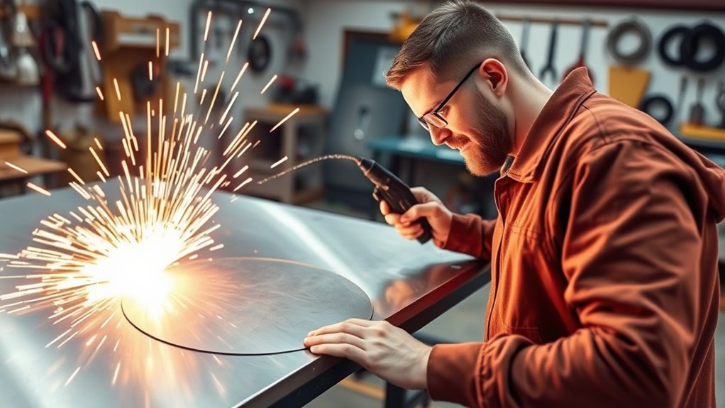
Clean plasma-cut circles come from controlling the torch path, cut height, speed, air supply, and kerf rather than relying on freehand motion. A pivoting circle guide is usually the easiest choice for a handheld torch, while CNC holes need tuned lead-ins, motion control, and torch-height settings.
Last updated: July 19, 2026
Quick Answer
Mark the center, secure a compatible circle guide or template, set the cutter from its manual, and make a test cut on matching scrap. Keep the torch square and moving smoothly. For CNC holes, use the correct lead-in, kerf compensation, cut direction, and small-hole settings instead of applying one speed rule to every circle.
Key Takeaways
- Use a center-pivot guide for repeatable handheld circles; freehand cutting is best reserved for rough work.
- Base amperage, air pressure, speed, pierce height, and cut height on the cutter’s manual and the metal thickness.
- Account for kerf and the guide’s torch offset before locking the radius.
- For CNC internal circles, use the correct cut direction, lead-in, overburn, and torch-height strategy.
- Dry air, sound consumables, a square torch, rigid motion, and a clean work-lead connection all affect roundness and edge quality.
At a Glance
| Time Required | About 15–45 minutes for setup, a scrap test, and one circle |
| Difficulty | Beginner to intermediate; CNC tuning requires more experience |
| Tools Needed | Plasma cutter, compatible circle guide or template, center punch, tape measure or calipers, clamps, scrap metal, and required PPE |
| Cost | Little to no added cost if you already own a compatible guide; accessory cost varies by torch and guide |
Warning: Plasma cutting exposes you to intense light, hot metal, sparks, electrical hazards, noise, and metal fumes. Follow the cutter’s manual, use the correct filter shade and protective clothing, remove combustibles, provide effective ventilation, and do not cut closed containers or unknown coated metal.
Understanding Plasma Cutting Basics
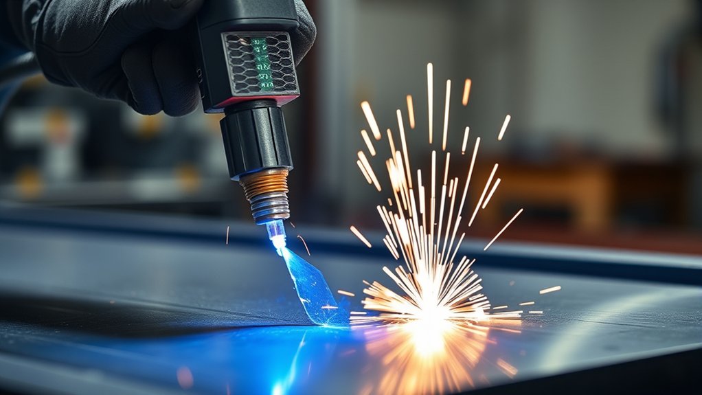
A plasma cutter sends an electrically conductive, high-temperature gas jet through the workpiece and blows molten metal out of the cut. It works on conductive metals such as mild steel, stainless steel, aluminum, copper, and brass. It does not cut wood, glass, stone, or other nonconductive materials with a standard transferred-arc torch.
Circle quality depends on more than the steadiness of your hand. The main variables are the metal type and thickness, consumable set, amperage, air or gas quality, torch-to-work distance, travel speed, cut direction, and the stiffness of the guide or CNC motion system. Start with the cut chart in your operator’s manual rather than a generic setting.
Choose the Right Circle-Cutting Method
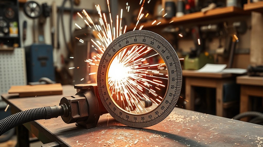
You can cut a circle with a pivoting guide, a rigid template, or a CNC table. Match the method to the accuracy you need:
- Center-pivot circle guide: Best for repeatable handheld circles. The pivot holds a fixed radius while the torch travels around the center.
- Rigid template: Useful when the center cannot be drilled or punched. The template must be offset for the torch tip or drag shield and the kerf.
- CNC table: Best for repeat production and detailed parts, but only when the toolpath, height control, motion system, and cut parameters are tuned.
- Freehand: Acceptable for rough openings that will be ground or covered, but rarely the best option for a finished circle.
The Eastwood Plasma Cutting Guide, for example, lists a 3 3/4-inch to 17-inch circle range. That specification applies only to that accessory. Confirm torch diameter, tip style, standoff method, and model compatibility before buying or attaching any guide.
Products Worth Considering

fit SG-55 AG-60 WSD-60 Plasma Cutter Torch

Roller Guide Wheel Spacer

WITH GRADUATED SCALE: This plasma cutter comes with a graduated scale. This design enables the user to use the scale to intuitively and conveniently locate the cutting diameter, cutting more convenient and quick.
Measure the Radius and Account for Kerf
First decide whether the finished part is the disk, the hole, or both. The plasma arc removes a strip of material called the kerf, so placing the torch centerline directly on the finished dimension can make the result too large or too small.
- Mark the finished circle diameter and exact center.
- Measure the distance from the guide’s pivot to the centerline of the plasma arc, not simply to the outside of the torch body.
- Adjust for kerf according to which side of the line is the finished part.
- Lock the guide and verify the radius at several points before cutting.
- Make a test circle on scrap of the same metal and thickness, then measure it after it cools.
Pro Tip: Draw a short test arc with the guide before firing the torch. If the torch body, hose, guide wheel, or pivot binds anywhere in the rotation, correct it before the cut starts.
Techniques for Centering and Stability
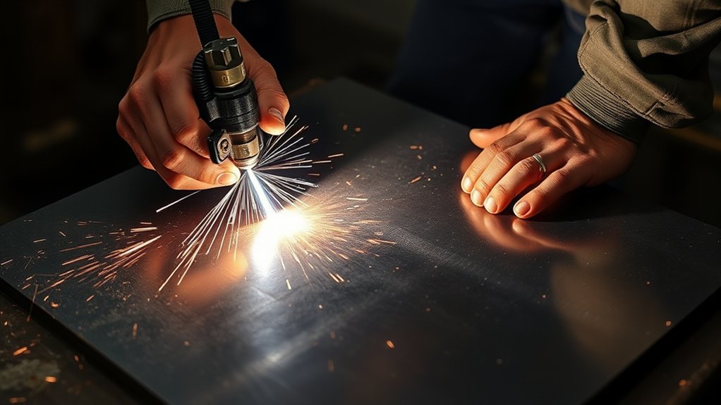
Accurate circles start with a center that cannot wander. Use a center punch for a pointed pivot, or drill a small pilot hole when the guide uses a pin or thumb screw. Clamp the workpiece so it cannot shift as the torch cable moves.
Centering Pin Techniques
A pointed pivot is fast and leaves only a small mark, but it needs a deep enough punch mark to stay seated. A through-hole pin or thumb-screw attachment gives a stronger mechanical hold and is better when the center area will become scrap.
Set the pivot perpendicular to the plate. A leaning pin changes the effective radius as the guide rotates. After setting the radius, rotate the unlit torch through a full circle and confirm the guide remains flat.
Stability Attachment Methods
Thread and tighten every guide connection according to the accessory instructions. Remove rust, heavy scale, or debris under guide wheels because even a small bump can change torch height. Support thin sheet so it does not sag during the cut.
Route the torch lead so it follows the movement without pulling the guide inward or outward. Do not wrap the lead tightly around your arm or body.
Set Up the Plasma Cutter for an Accurate Circle
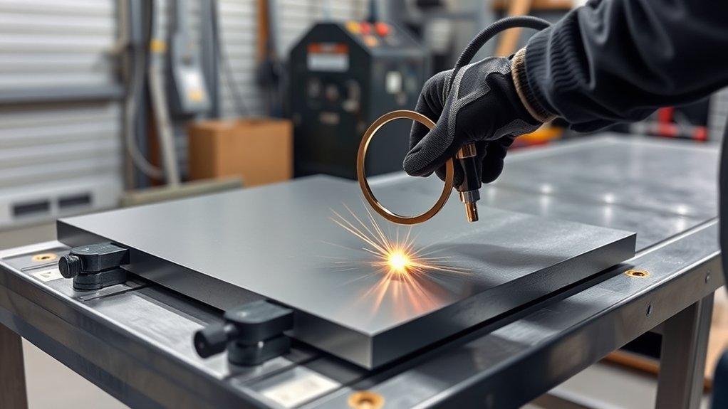
- Check the metal. Confirm the material is conductive, identify any coating, and clean the work-lead contact area to bare metal.
- Inspect the consumables. Replace a damaged nozzle, electrode, shield, or retaining cap with the correct parts for the process.
- Prepare the air supply. Supply the pressure and flow required by the manual. Drain the compressor and use suitable filtration so the air reaching the cutter is clean, dry, and free of oil.
- Select the cut settings. Use the manufacturer’s chart for the metal, thickness, consumables, and power level. Do not assume maximum amperage gives the cleanest circle.
- Set the standoff. Use a drag shield only when the torch and consumables are designed for drag cutting. Otherwise maintain the specified torch-to-work distance.
- Attach the work lead. Clamp it to clean metal on the workpiece or a properly connected cutting table, as the operator’s manual allows.
- Run a scrap test. Look for full penetration, manageable dross, a steady arc, and a cut trail that exits through the bottom rather than spraying back on top.
Keep the torch square to the plate and move at a smooth rate. Too fast can leave top spatter, incomplete penetration, or high-speed dross. Too slow can widen the kerf, round the top edge, and create low-speed dross. The correct speed is the one that matches the cut chart and produces a clean test cut.
Products Worth Considering

[Achieve Precise Cuts] PT31 Plasma Cutting Consumables – Your Essential Tool for Efficient Cutting! Whether you're working with sheet metal, steel, or any other material, superior cutting performance ensure clean, accurate, and smooth cuts.

PACKAGE INCLUDED: 5 Pcs Cup-15 Pcs Electrodes-10 Pcs Ring-30 Pcs Tip(Standard)
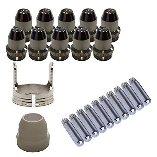
Only Compatible with BROWN Color Lotos LTP5800D , LTP5000D, LTPDC2000D.
How to Cut a Circle With a Handheld Plasma Cutter
- Lay out the circle and mark its exact center.
- Clamp the plate securely and clear the area below the cut so the drop cannot strike a hose, cable, or combustible surface.
- Install the compatible circle guide and set the pivot-to-arc radius, including the needed kerf offset.
- Position the torch at the starting point. When possible, start in the waste area and approach the finished line rather than piercing directly on it.
- Put on all required PPE, start ventilation, and warn nearby people before striking the arc.
- Fire the torch using the pierce method specified in the manual. On handheld systems, angling the torch during an interior pierce can direct molten blowback away from the nozzle, but return it to square before following the circle.
- Move continuously around the pivot without stopping, twisting the guide, or changing torch angle.
- Complete the cut, release the trigger, and allow post-flow air to cool the torch. Do not touch the cut edge or drop until it has cooled.
- Measure the circle. Adjust radius, speed, or standoff on scrap before cutting the final part if needed.
Fix Out-of-Round CNC Plasma Cuts
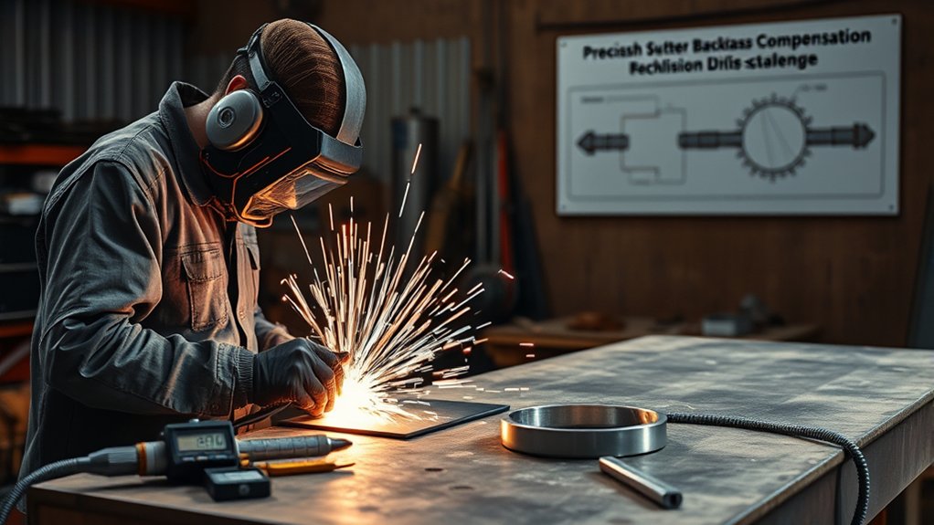
An oval, flat spot, or wobble does not automatically prove the plasma process is at fault. It may come from motion error, torch-height behavior, worn consumables, gas flow, or the toolpath.
Test the Motion System Before Replacing Parts
Replace the torch temporarily with a fine-tip marker and run the circle program without cutting. If the drawn circle is not round, inspect axis calibration, loose pinions, belt tension, bearings, couplers, gantry squareness, and backlash. Measure lost motion with a dial indicator where practical.
If the marker circle is round but the plasma-cut circle is not, test with torch height held at the correct fixed cut height. Improvement points toward height-control timing or programming rather than X-Y motion.
Reduce Backlash Without Overbuilding
Correct the specific source of play instead of assuming one drive design is always best. Rack-and-pinion, belt, lead-screw, ball-screw, and direct-drive systems can all cut accurately when they are properly sized, aligned, tensioned, and maintained. Preloaded components can reduce lost motion, but incorrect preload can add friction, wear, or binding.
Tune CNC Circle and Small-Hole Parameters

Set Speed by Hole Size and the Cut Chart
There is no universal circle speed. Hypertherm recommends 60% of the manual’s feed rate for holes under 1 inch in one general hole-cutting guide, but that is a starting point for that CNC context, not a rule for every machine, material, or large handheld circle. Use your system’s cut chart, CAM rules, and scrap tests.
Use THC Lockout When the Process Requires It
Voltage-regulated torch height control can react poorly during short, slow features because speed changes affect arc voltage. Some CNC processes therefore lock out voltage control during small holes after the pierce and height transition. Do not disable all height functions blindly: initial height sensing, pierce height, cut height, and voltage control perform different jobs. Follow the table, THC, plasma-system, and CAM documentation.
Program Lead-Ins, Overburn, and Pierce Delay
For internal circles, place the pierce and lead-in in the scrap center. Give the arc time to penetrate and the torch time to reach cut height before it meets the finished radius. A radiused or outward-spiral lead-in can smooth the entry. Avoid a long conventional lead-out that crosses the kerf and digs a divot into the saved edge. A small programmed overburn may close the circle more cleanly.
Use the Correct Cut Direction
With standard clockwise-swirl consumables, the squarest side is normally on the right of forward torch travel. That means an external contour usually runs clockwise, while an internal hole usually runs counterclockwise. Confirm the rule for your torch and consumables because specialized swirl configurations may differ.
Note: Very small, tight-tolerance holes may require high-definition plasma, drilling, machining, or another process. A conventional plasma system cannot make every hole perfectly cylindrical or burr-free.
Design and Machine-Rigidity Considerations

A flexible frame, loose torch mount, vibrating gantry, or poorly supported plate can distort a circle even when the G-code is correct. Check the complete cutting system rather than focusing only on the plasma power source.
Minimize Backlash Effects
Inspect drive components for looseness, uneven wear, damaged teeth, loose set screws, and poor alignment. Tune acceleration so the machine can follow a small radius without overshoot or motor stalls. Recalibrate steps per unit after mechanical changes.
Enhance Machine Rigidity
Square the torch in both axes, tighten the mount, support the plate, and keep the gantry and rails clean. Reinforce a machine only after identifying measurable flex; unnecessary weight can reduce acceleration and make small-feature motion worse.
Common Mistakes When Cutting Plasma Circles
- Using one speed for every circle: Diameter, thickness, amperage, consumables, and machine response change the correct speed.
- Ignoring kerf and torch offset: This produces a disk or opening that misses the target diameter.
- Letting the pivot or template move: A loose center, shifting plate, or cable pull changes the radius during the cut.
- Starting on the finished edge: A pierce mark or uncontrolled lead-in can leave a notch in the circle.
- Using worn or incorrect consumables: A damaged nozzle can deflect or widen the arc and increase bevel.
- Running wet or oily air: Contaminated air reduces cut consistency and consumable life.
- Setting the torch too high or low: Incorrect standoff changes bevel, kerf, and dross.
- Assuming THC should always be on or off: The correct choice depends on the feature, controller, and programmed height sequence.
- Using the wrong cut direction: The finished edge may end up on the lower-quality side of the kerf.
- Making a poor work-lead connection: Attach the work lead to clean metal as directed by the manual; do not rely on a painted, rusty, or loosely connected path.
Troubleshooting Circle Cut Quality
| Problem | Likely Causes | What to Check |
|---|---|---|
| Circle is oval or has a flat spot | Backlash, loose drive parts, acceleration limits, THC transition, damaged consumables | Run a marker test, inspect motion, test fixed cut height, rotate or replace consumables |
| Circle is too large or too small | Wrong radius, kerf compensation, guide offset, or axis calibration | Measure pivot-to-arc distance, verify inside/outside compensation, calibrate axes |
| Heavy dross | Speed too fast or too slow, wrong amperage, poor air, worn consumables | Compare with the cut chart and make controlled scrap tests |
| Excessive bevel | Torch not square, wrong height, worn nozzle, wrong cut direction | Square the torch, set standoff, inspect consumables, reverse the path if required |
| Notch at start or end | Pierce on finished line, poor lead-in, kerf crossing, unsuitable lead-out | Move the pierce to waste, use a radiused lead-in, tune overburn |
| Torch dives during a small hole | Voltage control reacts to deceleration or kerf crossing | Use the controller’s small-feature THC lockout and correct lead-in sequence |
Software Solutions for Smoother CNC Cuts

Clean geometry reduces tiny direction changes that can show up as facets or vibration. In Fusion 360, Vectric products, or another CAD program, create a true circle or clean arc geometry instead of tracing a rough bitmap with many nodes. In SheetCAM or another CAM program, verify units, curve tolerance, lead-in type, cut direction, kerf compensation, and small-hole rules before posting the toolpath.
Do not copy an import-tolerance number without checking whether the file and software use inches or millimeters. A setting such as 0.01 represents very different physical distances in those unit systems. Preview the toolpath at high zoom and run it with a marker before cutting valuable plate.
If a controller such as MASSO does not provide the geometry-cleanup feature you need, repair the vectors in CAD or CAM before generating G-code. Controller compensation cannot fully correct a lumpy source drawing.
Maintenance and Community Troubleshooting
Repeatable circles require a repeatable machine. Use the maintenance schedule in the plasma cutter, torch-height control, compressor, and CNC manuals.
- Inspect consumables: Look for an enlarged or irregular nozzle orifice, electrode wear beyond the manual’s limit, cracks, debris, and damaged seals.
- Maintain clean, dry air: Drain the compressor and service filters and dryers at the specified intervals.
- Check motion components: Inspect belts, racks, pinions, screws, couplers, bearings, rails, and torch mounts for looseness or wear.
- Clean and square the system: Remove debris from rails and slats, square the torch, and support warped plate.
- Check cables and connections: Tighten only with power isolated and according to the service manual. Replace damaged torch leads, work leads, and air hoses.
- Record working settings: Save the material, thickness, consumables, amperage, speed, height, lead-in, and measured result after a successful test.
Manufacturer support, experienced table builders, and user communities can help with unusual problems, but forum advice should not override the operator’s manual, cut chart, or safety requirements.
Frequently Asked Questions
What materials can a plasma cutter cut?
A standard transferred-arc plasma cutter cuts electrically conductive metals, including mild steel, stainless steel, aluminum, copper, and brass. It does not cut wood, glass, concrete, or most plastics.
How do I choose the right plasma cutter?
Match the machine’s recommended cut capacity and pierce capacity to the metal and thickness you use most. Also check input power, duty cycle, air-flow demand, consumable availability, torch options, CNC compatibility, and the quality of the manufacturer’s cut charts and support.
Can I use a plasma cutter indoors?
Only in a suitable hot-work area with effective ventilation, fire controls, required PPE, and enough clearance for sparks and falling metal. Coated metals can produce especially hazardous fumes. Do not treat an open door or a small fan as proof that exposure is controlled.
Can a plasma cutter engrave or mark metal?
Some plasma systems support dedicated marking or gouging processes, consumables, gases, and software settings. Do not assume that simply lowering amperage turns every cutting torch into an engraving tool; follow the manufacturer’s approved process for your model.
What protective gear is needed for plasma cutting?
Use eye and face protection with the filter shade required for the arc current and task, flame-resistant clothing, suitable gloves, hearing protection when needed, and protective footwear. Respiratory protection may also be required after a proper hazard assessment; ventilation should control fumes at the source.
Why is my plasma-cut circle not round?
For a handheld cut, check the center pin, guide stiffness, cable pull, radius setting, and torch angle. For CNC, run a marker test and inspect backlash, axis calibration, acceleration, torch-height timing, consumables, and gas flow.
Should I turn off torch height control for small holes?
Many CNC processes lock out voltage-regulated height correction during small holes, but they still use a correct initial height, pierce height, and cut height. Use the small-feature settings recommended by your plasma system, THC, table, and CAM provider rather than disabling the whole height sequence.
Conclusion
For a handheld plasma cutter, the shortest path to a cleaner circle is a secure center-pivot guide, correct kerf allowance, steady torch movement, and a test cut on matching scrap. For CNC circles, add accurate motion, a square torch, clean geometry, tuned lead-ins, the proper cut direction, and a controlled height sequence. Use the manufacturer’s cut chart as the baseline, then change one variable at a time and record the measured result.
Sources
- Hypertherm: Basic tips to improve plasma cut quality — cut direction, consumables, torch squareness, height, speed, gas delivery, and motion checks
- Hypertherm: How to cut better plasma holes — hole-size expectations, center lead-in, overburn, and the 60% small-hole starting point
- Hypertherm: Hole-quality troubleshooting — THC lockout, lead-ins, lead-outs, nozzle selection, and small-hole programming
- Miller: Introduction to plasma pattern cutting — templates, circle guides, standoff, work-lead contact, and piercing technique
- OSHA 29 CFR 1910.133 — eye and face protection and filter-shade requirements
- OSHA: Controlling hazardous fume and gases during welding — plasma-cutting fumes, ventilation, coatings, and exposure controls