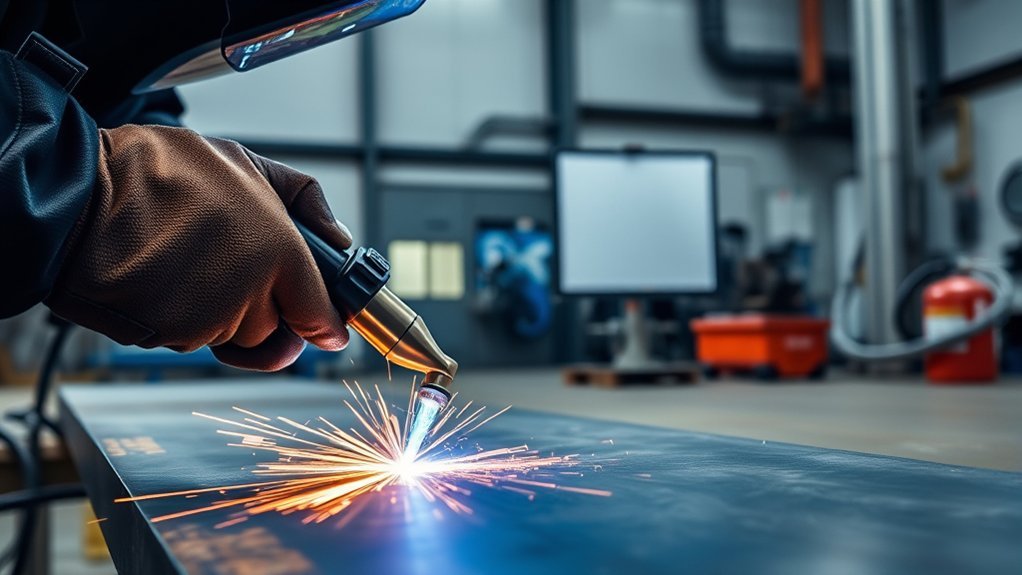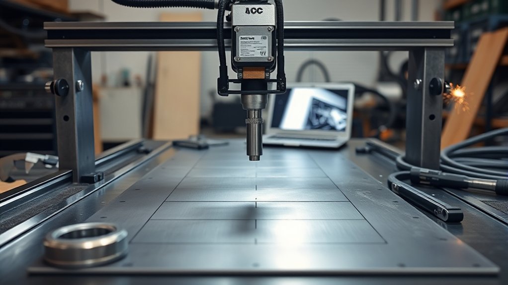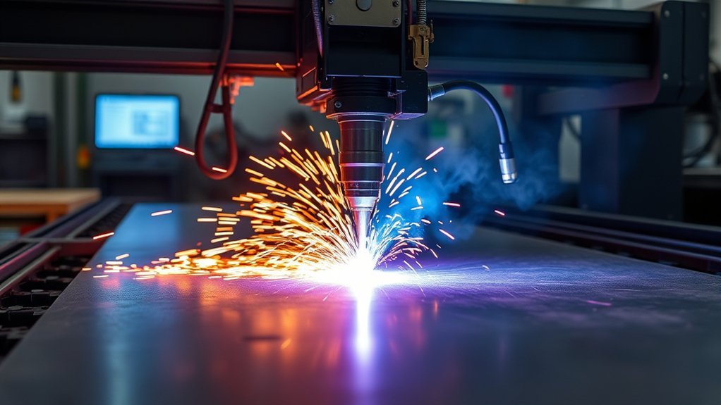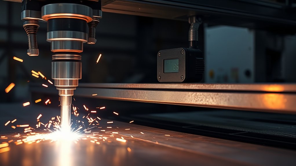
A CNC plasma cutter turns a digital part drawing into a repeatable cut in conductive metal. The software builds the toolpath, the CNC moves the torch, and the plasma system melts and blows metal out of the kerf. Clean results depend on matching the cut chart, motion system, torch height, air supply, consumables, and safety controls to the job.
Quick Answer
A CNC plasma cutter uses computer-controlled X-, Y-, and Z-axis motion to guide a plasma torch over conductive metal. An electric arc ionizes the cutting gas, the plasma jet melts the metal, and gas flow ejects it. CAD/CAM settings, torch height, speed, clean gas, and sound consumables control the final cut.
Key Takeaways
- CNC plasma cuts electrically conductive metals with a high-speed ionized gas jet.
- CAD/CAM software creates the toolpath, kerf offset, cut order, leads, and machine code.
- Torch Height Control uses initial height sensing and divided arc-voltage feedback to manage pierce and cut height.
- The manufacturer’s cut chart is the starting point for current, speed, gas, pierce delay, and height.
- Dry gas, firm work-lead contact, square motion, and healthy consumables improve edge quality.
- Plasma cutting needs controls for arc radiation, fumes, noise, sparks, fire, electric shock, and machine motion.
At a Glance
| Time Required | A simple file and test cut may take minutes; setup and cutting time rise with part count, detail, thickness, and material handling. |
| Difficulty | Intermediate. Safe operation requires machine training, cut-chart use, and basic CAD/CAM and troubleshooting skills. |
| Tools Needed | CNC table, compatible plasma power supply and machine torch, CAD/CAM software, clean gas supply, fume control, measuring tools, and required PPE. |
| Cost | Varies widely. Track material, electricity, gas or compressed air, consumables, labor, cleanup, and rejected parts as cost per finished part. |
What’s in This Article
- What a CNC Plasma Cutter Does and Why It’s Used
- Motion Control: Motors, Drives, and Path Accuracy
- Torch Height Control: Elements, Setup, and Operation
- Arc Basics: Plasma Generation, Voltage, and Standoff
- From File to Finished Part: Workflow, Cut Quality, and Maintenance
- Air Supply, Work Lead, and Cut Direction
- CNC Plasma Cutting Safety
- Common Cut Quality Problems and What They Mean
- Maintenance Schedule
- Frequently Asked Questions
- Conclusion
- Sources
What a CNC Plasma Cutter Does and Why It’s Used
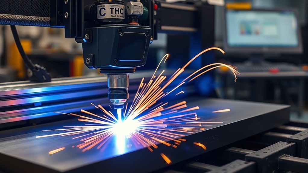
A CNC plasma cutter combines a plasma power supply, machine torch, cutting table, motion system, CNC controller, and software. It cuts steel, stainless steel, aluminum, and other electrically conductive metals. It does not cut wood, glass, stone, or other nonconductive material with the plasma arc.
The power supply creates an electric arc between the torch electrode and the workpiece. Gas passing through the nozzle becomes ionized, forming a narrow, high-speed plasma jet. That jet melts the metal, while gas flow pushes molten material out of the kerf. Hypertherm describes the same melt-and-eject process in its plasma cutting process overview.
You create or import a part drawing, then the CNC system follows the programmed toolpath with automated torch motion. This gives you repeatable shapes, controlled kerf placement, and less manual layout work.
CNC plasma works well for brackets, gussets, frames, flanges, signs, art panels, repair parts, and production blanks. A single table can support prototypes, small batches, and regular production. The practical limit depends on the plasma system’s rated capacity, the table, duty cycle, gas process, material, and cut-quality target.
Main Parts of a CNC Plasma System
- CAD software: Creates or edits the part geometry.
- CAM and nesting software: Applies leads, cut direction, kerf compensation, cut order, process settings, and sheet layout.
- CNC controller: Reads the machine code and coordinates motion and plasma signals.
- Motion system: Moves the gantry and Z axis through motors, drives, rails, racks, belts, or screws.
- Plasma system: Supplies current, gas, torch, and consumables for the cut.
- Torch Height Control: Finds the plate, sets pierce height, and regulates cut height.
- Fume-control system: Uses a downdraft table, local exhaust, or a correctly designed water table.
Motion Control: Motors, Drives, and Path Accuracy
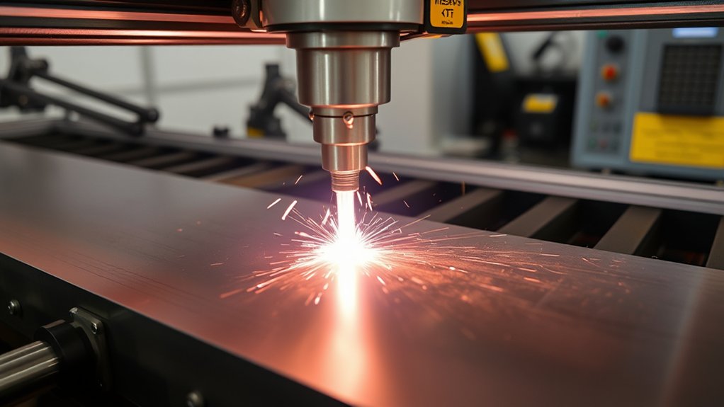
The motion system controls how the torch moves across the table. The controller reads the machine code and turns each move into coordinated X-, Y-, and Z-axis commands.
Stepper motors can work well on many light-industrial tables. Servo systems use encoder feedback and can detect or correct some position error. Neither motor type guarantees a good cut by itself. The frame, gantry, drives, gearing, rails, tuning, electrical noise control, and software settings must work together.
Loose pinions, worn bearings, dirty rails, belt stretch, backlash, or a gantry that is not square can cause chatter, mismatched corners, uneven kerf, and out-of-round holes. A rigid gantry and smooth acceleration matter most around small features and direction changes.
| Component | Function | What to Check |
|---|---|---|
| Motors | Generate axis motion | Torque, missed steps, encoder faults, overheating |
| Drives | Control motor current and motion | Tuning, fault history, cable condition |
| Controller | Coordinates code, motion, and torch signals | Post-processor match, acceleration, input/output timing |
| Rails and bearings | Guide linear travel | Cleanliness, play, lubrication, alignment |
| Rack, belt, or screw | Transfers motor motion | Backlash, tension, wear, loose fasteners |
Pro Tip: Check mechanical looseness, torch squareness, and gantry alignment before changing plasma settings. A motion problem can look like a speed, height, or consumable problem.
Products Worth Considering
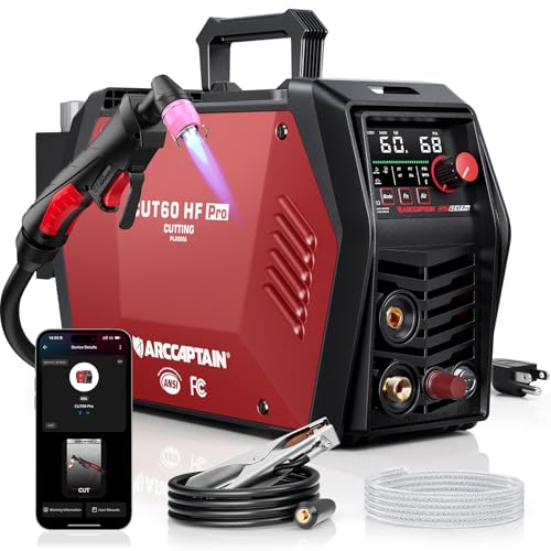
[ENHANCED CUTTING CAPACITY] - Equipped with a 3nd-Gen MCU, this plasma cutter delivers powerful output across both voltage options. On 120V, it supports a cutting range of 10–16 mm when the air pressure is kept above 55 PSI. Switching to 240V unlocks heavier performance, cutting 16–26 mm (up to 15/16" / 24 mm) with the recommended 55–75 PSI air pressure. The arc remains stable on stainless steel, carbon steel, aluminum, and copper, producing smooth edges with minimal slag and reducing follow-up grinding.
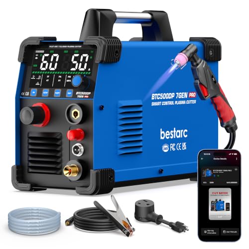
[Smart APP Remote Control Up to 98FT] Control your plasma cutter from up to 98 ft (30 m) away via Bluetooth APP. Adjust cutting current, switch cutting modes, save preferred settings, monitor operating status, and check error codes directly from your phone. Reduce trips back to the machine and work more efficiently—ideal for workshops, auto repair, farms, garages, and DIY projects.

[Smart APP Remote Control Distance to 98 feet] Control this plasma cutter remotely via Bluetooth APP from up to 98 feet (30 meters) away. Adjust cutting current, switch modes, save your preferred settings, and use remote diagnostics to check operating conditions in real time-no need to walk back to the machine. This smart design improves flexibility and efficiency for car repairing, workshop, farm, hobbies repairing, small job projects, Home, DIY.
Torch Height Control: Elements, Setup, and Operation
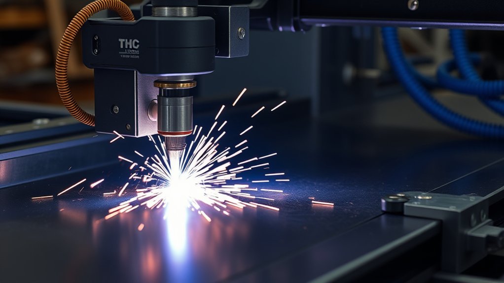
Motion control sets the path, while Torch Height Control (THC) manages the torch’s vertical position. Correct height protects cut quality and consumable life.
A typical THC cycle has several stages:
- Initial Height Sensing: The Z axis finds the plate by ohmic contact, a floating head, motor stall, or another sensing method.
- Pierce position: The torch retracts to the pierce height listed in the cut chart.
- Pierce and delay: The arc transfers to the plate and stays at pierce height long enough to pass through the material.
- Cut position: The torch moves down to the charted cut height as table motion begins.
- Voltage control: After the cut becomes stable, the THC compares divided arc voltage with the target and moves the torch to maintain arc length.
- Anti-dive control: The CNC or THC limits height correction during slow corners, small holes, lead-outs, or kerf crossings, where voltage can change for reasons other than plate height.
Arc voltage changes with the distance between the electrode and the workpiece. A longer arc normally produces higher voltage; a shorter arc produces lower voltage. The target must come from the cut chart for the exact process. Hypertherm notes that mechanized settings are often between 100 and 200 VDC, but that is not a universal setup range.
Pierce height is higher than cut height so molten spatter is less likely to damage the nozzle. A common rule of thumb is about 150% to 200% of cut height, but the machine’s chart always takes priority. Run a test coupon and inspect the edge before production.
Note: A CNC interface should use the plasma system’s approved divided-voltage output or serial interface. Raw arc voltage can be lethal. Do not open the power supply or make an improvised voltage connection unless the manufacturer’s procedure allows it and a qualified person performs the work.
Products Worth Considering

Optoisolated input working at 5 to 24VDC or Open collector.

SCOPE OF APPLICATION: Wide clamping range, torch range from 12mm‑38mm, suitable for a variety of work scenarios

60amps output current, suitable for Bestarc BTC500XP BTC650XP cutting machine
Arc Basics: Plasma Generation, Voltage, and Standoff
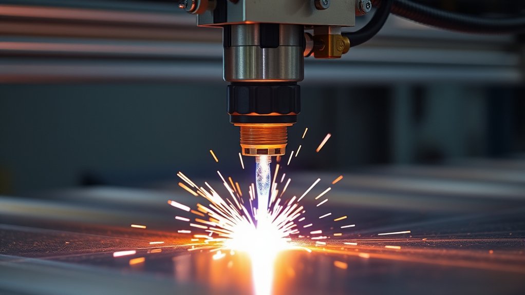
The arc does the cutting work. The plasma system adds energy to a gas until part of the gas becomes ionized and electrically conductive. The nozzle constricts the jet, increasing its speed and energy density.
The plasma jet melts a narrow path through the workpiece. The gas stream pushes the molten metal out through the bottom of the kerf. Plasma arcs can approach 40,000°F, or about 22,000°C, but temperature alone does not predict cut quality.
Current, nozzle size, gas, pressure or flow, cut speed, pierce delay, torch height, and material thickness must match. Changing one variable can affect the others. Start with the manufacturer’s cut chart instead of a generic internet setting.
| Parameter | Starting Point | Why It Matters |
|---|---|---|
| Amperage and consumable | Use the charted process for material and thickness | Controls energy, capacity, kerf, and consumable loading |
| Arc voltage | Use the charted THC value and approved divided signal | Helps regulate torch-to-work distance |
| Pierce height and delay | Use the cut chart | Protects the nozzle and allows full penetration before travel |
| Cut height | Use the process-specific chart, not one universal gap | Strongly affects bevel, kerf, dross, and parts life |
| Travel speed | Use the chart, then tune with test cuts | Affects penetration, lag lines, dross, heat input, and detail |
The cut chart is the baseline. Change one variable at a time, document the result, and keep the setting that improves the finished part.
From File to Finished Part: Workflow, Cut Quality, and Maintenance
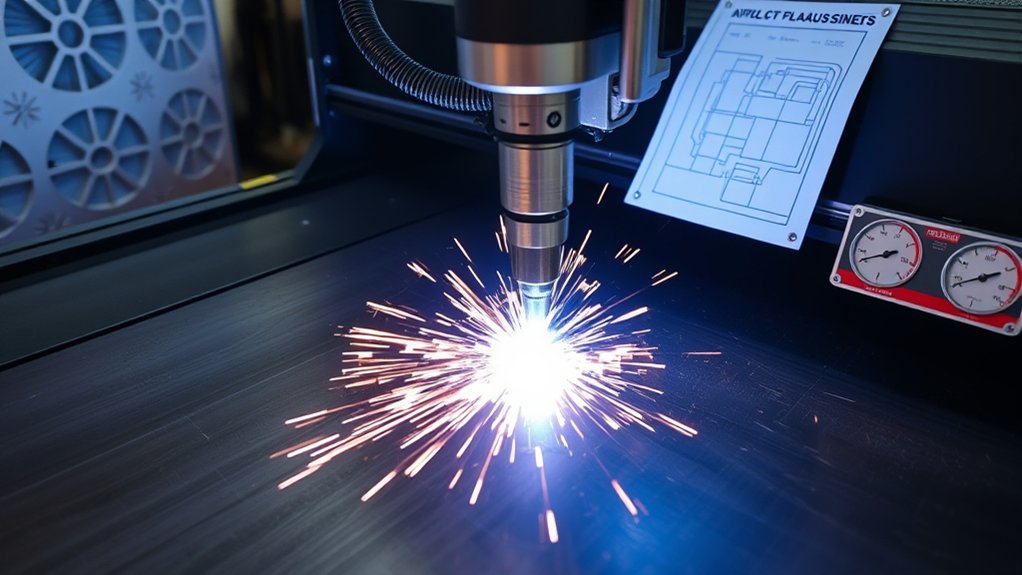
Your process starts before the arc strikes. Hypertherm’s CAD/CAM overview explains that CAM software can check geometry, apply kerf compensation, set cut sequence, add leads, nest parts, and output code for the CNC.
- Confirm the job: Verify material grade, thickness, dimensions, tolerance, quantity, grain needs, and the edge that will remain on the finished part.
- Prepare the drawing: Import a clean DXF or create the geometry in CAD. Remove duplicate lines, open contours, tiny segments, and features below the process capability.
- Choose the process: Select the material, thickness, gas, amperage, consumable, and quality level listed for your system.
- Build the toolpath: Add kerf compensation, lead-ins, lead-outs, pierce delay, cut direction, and tabs where needed. Cut inside profiles before outside profiles.
- Nest the parts: Arrange parts to use the sheet well while leaving enough space for kerf, heat, clamps, slats, and tip-up risk.
- Post the code: Use the correct post-processor for the CNC and table. Review warnings before sending the file.
- Inspect the machine: Check consumables, gas supply, work lead, torch squareness, slats, fume control, travel path, and emergency stops.
- Dry run safely: With the torch disabled when the machine allows it, confirm travel limits, cut order, clearance, and part placement.
- Run a test coupon: Use the charted settings. Inspect penetration, dross, bevel, top edge, hole shape, and dimensions before cutting the full sheet.
- Record the result: Save the working process, measured kerf, voltage, speed adjustment, consumable condition, and material lot notes.
Small inside profiles often need different speed and THC behavior than long straight cuts. The torch may not reach full speed in a small hole, so a responsive anti-dive strategy can matter as much as the nominal voltage.
Air Supply, Work Lead, and Cut Direction
Clean Gas and Compressor Capacity
Most air-plasma systems need clean, dry, oil-free compressed air. Moisture, oil mist, and particles can shorten consumable life and make the arc unstable. Hypertherm recommends a properly sized compressor, drying, and filtration for shop-air systems in its plasma gas selection guide.
Size the compressor by the plasma system’s required flow and pressure, not only by tank size or peak horsepower. Include pressure loss through hose, filters, dryers, and fittings. Check pressure while gas is flowing because static pressure can look normal even when flow is too low.
Work Lead Contact
The work lead completes the cutting circuit; it is not a substitute for the machine’s protective earth grounding system. Follow the table and plasma manufacturers’ grounding plan. Make clean metal-to-metal contact and remove rust, paint, scale, or coatings at the connection point. Route work and torch leads away from communication cables where the manufacturer directs to reduce electrical interference.
Cut Direction and the “Good” Side
Plasma gas swirl makes one side of a conventional cut squarer than the other. Toolpath direction should place the better edge on the finished part. The correct direction depends on torch swirl and machine convention, so use the plasma and CAM documentation rather than assuming every system is the same.
CNC Plasma Cutting Safety
Plasma cutting combines an electric arc, automated motion, hot metal, ultraviolet and infrared radiation, sparks, fumes, compressed gas, and high noise. Read the manuals for the plasma system and table before operation, and keep guards, interlocks, and emergency stops working.
Warning: Never cut a sealed container, tank, drum, pipe, or hollow part that may have held fuel, solvent, combustible dust, or pressurized material. Hot work can ignite residue or trapped vapor even when the container looks empty.
- Eye and face protection: Use safety glasses with side protection plus an arc-cutting helmet or shield with a filter shade approved for the current and process. Protect nearby people with suitable screens.
- Clothing and hands: Wear flame-resistant clothing, leather gloves, hearing protection, and sturdy footwear. Avoid synthetic clothing that can melt.
- Fume control: Use source capture such as a downdraft table, local exhaust, or a properly designed water table. Keep the plume out of the breathing zone. OSHA notes that plasma cutting generates airborne metal fume and that the base metal, coating, process, location, and ventilation affect exposure.
- Coatings and alloys: Identify paint, plating, primer, galvanizing, and the base metal before cutting. Lead, cadmium, beryllium, zinc, chromium, and other metals can require specific controls. Stainless steel cutting can create chromium-containing fume.
- Respiratory protection: Do not treat a disposable mask as a replacement for ventilation. Workplace respirator use may require hazard evaluation, medical clearance, fit testing, cartridge selection, training, and a written program.
- Noise: The plasma arc, compressor, exhaust system, and part handling can create hazardous noise. Measure exposure when needed and select hearing protection for the actual level.
- Fire prevention: Remove or shield combustibles and control sparks that can pass through openings. OSHA’s hot-work rule uses a 35-foot area for certain combustible-material precautions and requires fire-watch measures when hazards cannot be removed.
- Electrical and motion hazards: Disconnect and lock out input power before service. Keep clear of the gantry and Z axis during automatic motion, and never bypass a safety device.
Warning: Aluminum can generate hydrogen when cut over or under water. Do not cut aluminum on a water table unless the table manufacturer has designed and approved a system that prevents hydrogen accumulation. Never use hydrogen-containing plasma gas for underwater aluminum cutting.
Common Cut Quality Problems and What They Mean
Cut defects often point to a setup or maintenance issue. Start with the cut chart, then check consumables, gas quality, work-lead contact, torch squareness, motion, height, and speed. Make one change at a time.
| Problem | Likely Causes | First Checks |
|---|---|---|
| Soft, heavy bottom dross | Speed too slow, amperage too high for the nozzle/process, or standoff too low | Confirm the chart; increase speed in small steps; inspect height and consumables |
| Hard, narrow bottom bead | Speed too fast, standoff too high, current too low, or worn nozzle | Inspect nozzle; reduce speed in small steps; verify current and height |
| Top spatter | Speed too fast, torch too high, worn nozzle, or poor pierce transition | Check nozzle, speed, pierce delay, and cut height |
| Excess bevel | Wrong height, worn consumables, wrong direction, tilted torch, or speed error | Square the torch; inspect consumables; confirm direction and charted height |
| Rough or wavy edge | Wet gas, unstable pressure, worn parts, loose motion, bad work contact, or wrong speed | Drain and inspect air system; check work lead, rails, drives, and consumables |
| Incomplete penetration | Speed too fast, current too low, plate beyond process capacity, low gas flow, or poor work contact | Stop the job; verify capacity, current, speed, gas flow, and work lead |
| Out-of-round holes | Backlash, poor acceleration, wrong lead, THC diving, or feature below process capability | Check motion; use hole rules; lock or limit THC where required |
| Short consumable life | Piercing too low, wet or dirty gas, wrong parts, excessive pilot-arc time, or torch contact | Verify pierce height, gas quality, part selection, and IHS operation |
Hypertherm’s dross troubleshooting guide separates low-speed dross from high-speed dross because they need opposite speed corrections. That distinction prevents a common tuning mistake.
Maintenance Schedule
Maintenance intervals vary by system, environment, and arc-on time. Use the manufacturer’s manual as the final authority. The schedule below is a practical inspection framework, not a replacement for that manual.
| Interval | Checks |
|---|---|
| Before each cutting shift | Inspect the nozzle, electrode, shield, retaining cap, and gas holes; drain moisture; check pressure under flow; confirm work-lead contact, torch squareness, fume control, slats, guards, and emergency stops. |
| Weekly | Clean rails and racks as directed; check fasteners, backlash, cable carriers, breakaway mount, ohmic contact surfaces, filters, and water-table condition. |
| Monthly or by operating hours | Check gantry squareness, axis calibration, drive faults, torch lead condition, grounding and bonding connections, exhaust performance, compressor service items, and cut-data records. |
| At the manufacturer’s interval | Service internal filters, fans, coolant systems, electrical cabinets, bearings, and other protected components using lockout procedures and qualified personnel. |
Frequently Asked Questions
What Safety Gear Is Essential When Operating a CNC Plasma Cutter?
Use safety glasses with side protection, an arc-rated cutting helmet or shield with the correct filter shade, leather gloves, flame-resistant clothing, hearing protection, and sturdy footwear. Control fumes at the source. Respirator use should follow a hazard assessment and an applicable respiratory-protection program.
Can a Plasma Cutter Engrave or Mark Without Fully Cutting?
Many mechanized plasma systems can mark, scribe, or lightly gouge when they have a supported marking process and consumable set. Use the manufacturer’s marking chart and compatible CAM process. Do not simply reduce current at random, because an unsupported setup can damage parts or produce poor marks.
How Does Shop Ventilation Affect Plasma Cutting Fumes and Dust?
Good source capture keeps the plume away from the operator and nearby workers. A downdraft table, local exhaust hood, or correctly designed water table can reduce airborne contamination. The required control depends on the metal, coating, gas, cut time, room, and exposure measurements.
What Materials Are Unsuitable or Hazardous to Cut With Plasma?
The arc needs an electrically conductive workpiece, so it will not cut wood, glass, stone, or most plastics. Unknown coatings, plated metal, sealed containers, magnesium, beryllium-containing alloys, lead- or cadmium-coated parts, and aluminum over water can present serious fume, fire, or explosion hazards and need a specific risk assessment.
How Loud Is Plasma Cutting, and Do I Need Hearing Protection?
Noise varies with current, material, table design, compressor, exhaust, and part handling. Plasma cutting can exceed safe exposure levels, so use hearing protection and measure the work area when exposure is uncertain. In workplaces, follow the applicable noise and hearing-conservation requirements.
Why Do I Get So Much Dross on a CNC Plasma Cut?
First identify the dross type. Soft, heavy low-speed dross usually calls for more speed, while a hard narrow high-speed bead usually calls for less speed. Wrong height, current, gas quality, material condition, and worn consumables can also contribute. Start from the cut chart and change one setting at a time.
Does a CNC Plasma Cutter Need Dry Compressed Air?
Most air-plasma systems need clean, dry, oil-free air at the pressure and flow listed by the manufacturer. Moisture and oil can shorten consumable life and destabilize the arc. Use adequate filtration and drying, drain the system, and check pressure while gas is flowing.
Why Are My CNC Plasma Holes Out of Round?
Common causes include backlash, poor acceleration tuning, a loose gantry, the wrong lead-in, torch height changes inside the hole, and a hole that is too small for the process. Check motion first, then use the CAM software’s hole rules and the plasma manufacturer’s guidance.
Can a CNC Plasma Cutter Cut Aluminum?
Yes. Use the gas, consumables, speed, current, and height listed for aluminum in your system’s cut chart. Air plasma can cut aluminum, but the cut face may oxidize and may need preparation before welding. Water-table cutting needs a proven hydrogen-control design.
Conclusion
A CNC plasma cutter works best when the file, CAM rules, motion system, torch height, cut chart, gas supply, work lead, and consumables support the same goal: a clean and repeatable finished part.
Start with verified material and a correct process, inspect the machine, dry-run the path, and cut a test coupon. Then adjust one variable at a time. Keep records of amperage, speed, voltage, material thickness, measured kerf, and consumable life so you can repeat good cuts and diagnose bad ones faster.
Automation improves consistency, but it does not remove the need for trained setup, maintenance, fume control, fire prevention, and safe work practices.
Sources
- Hypertherm: How Does a Plasma Cutter Work? — plasma generation and the melt-and-eject cutting process.
- Hypertherm: CAD/CAM Cutting Software — CAD, CAM, nesting, G-code, kerf compensation, leads, and cut sequence.
- Hypertherm: Torch Height Control for Plasma Cutting — initial height sensing, pierce height, arc voltage, and cut-height control.
- Hypertherm: CNC Plasma Cut-Quality Tips — torch squareness, height, speed, angularity, and dross diagnosis.
- OSHA 29 CFR 1910.252 and OSHA Welding Fume Fact Sheet — hot-work fire controls, eye protection, ventilation, and metal-fume hazards.
- Hypertherm: Plasma Cutting Aluminum — aluminum process guidance and hydrogen hazards around water tables.