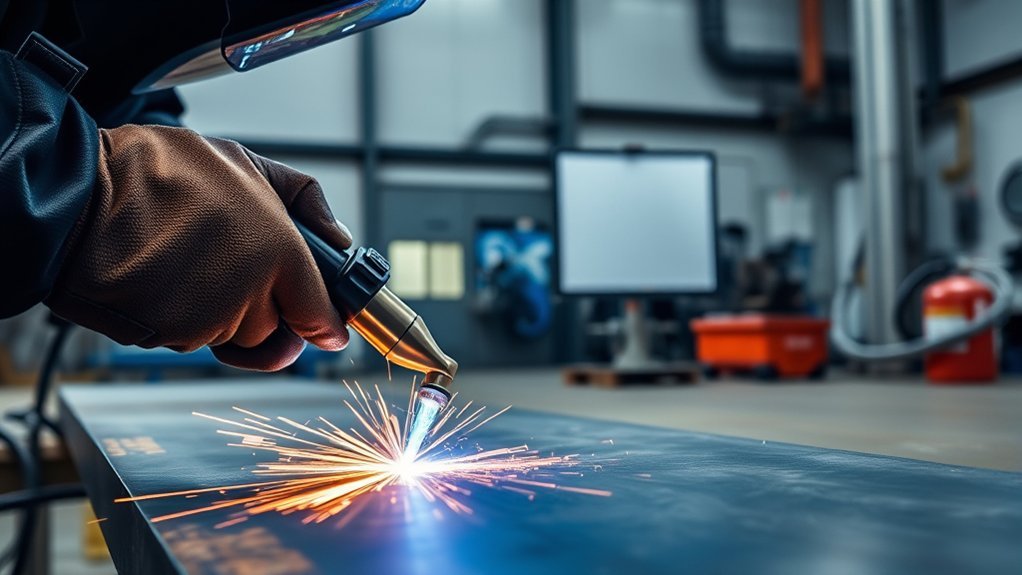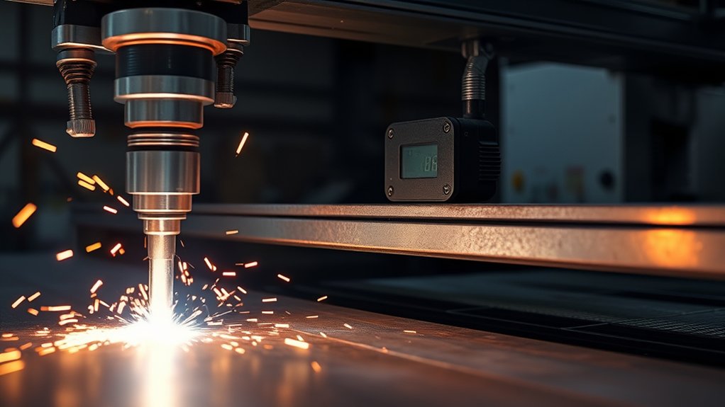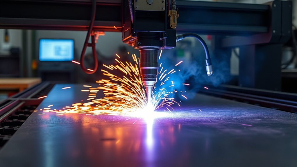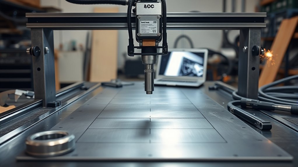
Building a 4×8 CNC plasma table is an advanced fabrication and machine-integration project. A successful table needs more than a steel frame and moving torch: the usable travel, plasma source, compressed-air system, motion hardware, controls, electrical installation, fume capture, emergency stops, and calibration process must work together safely.
Quick Answer
To build a 4×8 CNC plasma table, design for at least 48×96 inches of usable torch travel, fabricate a rigid and level steel base, install matched motion and control hardware, choose a plasma source with a supported CNC interface, size the air and fume systems correctly, and complete dry-run and test-cut calibration before production.
Key Takeaways
- A nominal 4×8 frame does not automatically provide a full 48×96-inch cutting envelope. Allow for torch diameter, lead-ins, edge pierces, hard stops, and overtravel.
- Choose a dedicated CNC-compatible plasma source with a machine torch, isolated start input, arc-transfer signal, and supported arc-voltage connection.
- Size the compressor from the plasma manufacturer’s continuous SCFM and pressure requirements, not from tank size or peak compressor output.
- Use a properly designed downdraft or water-table system, but do not assume either one removes every fume hazard.
- Test emergency stops, homing, limits, motion, air pressure, torch probing, and control signals with the plasma arc disabled before making a live cut.
At a Glance
| Time Required | Several weekends to several months, depending on design work, fabrication experience, purchased assemblies, electrical work, and ventilation installation |
| Difficulty | Advanced; requires welding, precision alignment, machine-control integration, and qualified electrical work |
| Tools Needed | Welder, metal saw, drill, clamps, engineer’s square, tape measure, level, dial indicator, wiring tools, multimeter, torque tools, and appropriate lifting equipment |
| Cost | Project-specific; price the plasma source, motion and control package, frame steel, air treatment, fume system, electrical installation, software, consumables, and safety equipment before fabrication |
Warning: A CNC plasma table combines lethal voltage, automatic machine motion, ultraviolet and infrared radiation, compressed air, hot metal, sparks, noise, and hazardous fumes. Use the plasma-source and controller manuals as the controlling instructions. Have branch-circuit, disconnect, protective-earth, and code-related work completed or approved by a qualified electrician.
Planning Your Table Size, Capacity, and Budget
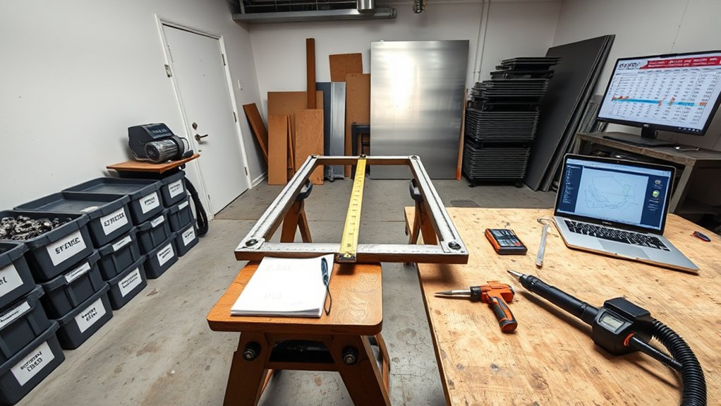
Start by defining the work envelope rather than the outside frame dimensions. A standard sheet is 48×96 inches, but the torch may need to travel past an edge for lead-ins, edge starts, probing, or service access. The slat opening, rail length, gantry travel, hard stops, and software limits must all support the required usable area.
Lock in the usable cutting envelope first. The frame, slat bed, rails, cable travel, and fume system should be designed around that envelope—not the other way around.
Define the Usable Cutting Envelope
A 49×97-inch slat opening can provide clearance around a 48×96-inch sheet, but it does not by itself guarantee that the torch can reach every required point. Model the torch centerline, Z-axis carriage, rail trucks, motor mounts, cable carriers, bumpers, home switches, and hard stops before cutting frame material.
Also measure the room around the machine. Leave space to:
- Load and unload full sheets without standing inside the gantry travel area
- Remove slats and clean the pan or plenum
- Reach the plasma source, air filters, control enclosure, disconnect, and emergency stop
- Service rails, motors, belts, racks, switches, and cables
- Route exhaust outdoors to an approved discharge point
- Keep the compressor away from metal dust and excessive heat
Set Material, Thickness, and Production Goals
List the metals and thicknesses you expect to cut most often. Do not choose a plasma source from its severance number alone. Compare its recommended cut capacity, production cut capacity, mechanized pierce capacity, duty cycle, cut chart, input power, and consumable availability.
A machine intended mainly for thin automotive panels has different acceleration, fume, and air requirements from a table expected to pierce 1/2-inch plate. Designing around 1/4-inch mild steel can be a useful personal baseline, but it does not guarantee that the machine will suit every material or workload.
Note: Recommended cutting capacity, pierce capacity, and maximum severance capacity are not interchangeable. A plasma source may sever a thick plate from an edge but be unable to pierce that thickness cleanly in automated service.
Create a Complete Budget Baseline
Create a bill of materials before welding the base. Include more than the obvious steel and motors:
- Frame tubing, gussets, leveling feet, casters, fasteners, and coatings
- Slats, removable slat holders, steel pan, plenum, duct, fan, or water-table hardware
- Linear rails or V-rails, racks or belts, pinions, bearings, motors, and gear reduction
- Z-axis slide, floating head, breakaway torch mount, and torch height control
- Control enclosure, motion controller, drives, power supplies, relays, contactors, safety components, and cooling
- Shielded cable, flexible cable, cable carriers, connectors, strain reliefs, and grounding hardware
- Plasma source, machine torch, CNC cable, work lead, consumables, and spares
- Compressor capacity, aftercooling, separator, coalescing filtration, dryer, drains, regulator, and air piping
- Computer, software licenses, post-processor work, and backup storage
- Qualified electrical installation, ventilation discharge, fire protection, PPE, and noise controls
Reserve part of the budget for corrections after testing. Rail shims, different motor pulleys, replacement cables, improved filtration, additional ducting, and revised torch mounts are common commissioning expenses.
Essential Components, Software, and Tools
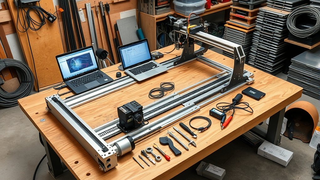
The core system includes a CNC-supported plasma source, compressed-air treatment, rigid frame, X-Y motion system, Z-axis, torch height control, machine controller, motor drives, safety circuit, and fume-control system. Select these as one integrated machine rather than as unrelated parts.
Products Worth Considering
![ARCCAPTAIN iControl CUT65 MP [CNC] Non-HF Plasma Cutter Machine, 65 Amp](https://m.media-amazon.com/images/I/512VnwHLmyL._SL500_.jpg)
[NON-HF BLOWBACK PILOT ARC] Uses a non-HF blowback pilot arc start to reduce electromagnetic interference, ideal for CNC systems. The non-contact arc cuts easily through rusty, painted, or expanded metal. Delivers up to 65A on 240V for smooth, clean cuts up to 32mm on steel, stainless steel, copper, and more.

WITH GRADUATED SCALE: This plasma cutter comes with a graduated scale. This design enables the user to use the scale to intuitively and conveniently locate the cutting diameter, cutting more convenient and quick.
![ANDELI 65 Amp Plasma Cutter [CNC Enabled][ Non-HF],1.06" Max Cut](https://m.media-amazon.com/images/I/51HzSS1IgqL._SL500_.jpg)
【Large Digital Display】The upgraded LED interface clearly displays key parameters such as air pressure, voltage, current, and working status in real time, allowing users to monitor machine performance and make timely adjustments for more efficient operation. If an issue occurs, the screen shows an error code to help quickly identify the problem and simplify troubleshooting.
Choose a CNC-Compatible Plasma Source
A suitable source should have manufacturer-supported connections for automated cutting. Depending on the controller, that normally includes:
- An isolated torch-start input
- An arc-transfer or arc-OK output
- A divided or otherwise isolated arc-voltage output for torch height control
- A machine torch or a hand torch specifically approved for mechanized use
- Consumables and cut charts for mechanized cutting
- A starting method compatible with nearby CNC electronics
Blowback-start or other low-EMI systems are usually easier to integrate than high-frequency-start sources. High-frequency starting can create severe radio-frequency and electromagnetic interference unless the complete machine is designed for it.
The Everlast PowerPro 256Si, sometimes called the PM256, should not be selected for this job. Its manufacturer manual says it is not intended for CNC plasma service. Use a dedicated CNC-supported source instead, such as a properly configured current PowerPlasma model or a mechanized Hypertherm Powermax65 SYNC. These are examples, not substitutes for comparing the required cut capacity, interface, power, air demand, and local support.
Size the Compressor and Air Treatment
Match the compressor to the plasma source’s required continuous flow at the specified inlet pressure. Do not select by receiver-tank size, displacement CFM, or a short peak-flow rating.
For example, the Powermax65 SYNC specification calls for clean, dry, oil-free air at 7.5 scfm and 85 psi while cutting. A different source may require a different flow and pressure.
The air system should include:
- A compressor able to meet continuous demand at the required pressure
- Enough duty cycle for the planned production time
- Low-restriction piping sized to limit pressure loss
- An aftercooling or moisture-removal stage
- A water separator and automatic or regularly serviced drains
- Filtration suitable for the plasma manufacturer’s air-quality requirement
- A final regulator and pressure gauge near the plasma source
Pro Tip: Check dynamic pressure while air is flowing through the torch. A gauge may show acceptable pressure at rest while undersized hose, clogged filters, or a weak compressor causes a large pressure drop during a cut.
Select the Motion System
The motion system must move the gantry quickly without racking, stalling, or oscillating. Common choices include:
| Drive Type | Advantages | Tradeoffs |
|---|---|---|
| Rack and pinion | Long travel, good speed, durable, common on full-size tables | Needs alignment, preload, guarding, and backlash control |
| Timing belt | Light, quiet, economical, easy reduction | Long belts can stretch, resonate, or lose tension |
| Lead or ball screw | High positioning resolution on short axes | Long screws can whip and are usually less practical for an 8-foot axis |
A full-size gantry often uses one motor on each side of the long axis. The controller must support independent homing or another reliable method of squaring the gantry. Size stepper or servo motors from gantry mass, desired acceleration, drive reduction, pinion diameter, friction, and required speed rather than copying a motor rating from a smaller machine.
Choose Current CAD, CAM, and Control Software
The software chain has three jobs:
- Create or import the part geometry.
- Generate plasma-specific toolpaths and G-code.
- Control machine motion, probing, arc start, and torch height.
AutoCAD remains suitable for 2D geometry. Autodesk Fusion can also create cutting setups, plasma tools, and 2D profile operations through its Manufacture workspace. Confirm that the selected post processor matches the exact machine controller before running the code.
SheetCam remains a plasma-focused CAM option for DXF and SVG files, nesting, lead-ins, kerf compensation, cut sequencing, and configurable post processors.
Mach3 can remain useful on an existing compatible machine, but it should be treated as a legacy choice. ArtSoft describes Mach4 as its direct replacement. LinuxCNC QtPlasmaC is another current plasma-oriented control option. Proprietary controllers may include their own control and CAM workflow.
Whichever system you choose, verify:
- Compatible motion-control hardware and drivers
- Plasma-specific post processor
- Home and limit-switch support
- Floating-head or ohmic-probe input
- Arc-OK and torch-on input/output mapping
- Arc-voltage and torch-height compatibility
- Anti-dive behavior near corners, holes, and deceleration zones
- Offline backup of configuration, material, tool, and post files
Essential Safety Equipment and Controls
Eye protection must match the cutting current. A blanket shade-5 rule is unsafe for many full-size tables. The Hypertherm Safety and Compliance Manual lists higher minimum shades as amperage rises; its table specifies a minimum shade 8 for plasma cutting at 61–80 A. Follow the exact plasma-source manual and applicable workplace requirements.
Use safety glasses with side protection beneath suitable filtered eye or face protection. Also provide flame-resistant clothing, leather gloves, hearing protection, protective footwear, welding curtains or screens, and respiratory protection when an exposure assessment shows it is needed.
The machine itself should include:
- A clearly marked, readily reachable emergency stop
- A control method that removes motion and torch-start permission when the emergency stop is activated
- Hard stops beyond normal software travel
- Home and limit switches protected from slag and impact
- A torch breakaway or collision mount
- Strain relief and enclosed terminals
- Guards where accessible racks, pinions, belts, or pinch points create a hazard
- A restricted-access zone around the complete motion envelope
Keep a suitable fire extinguisher nearby, remove combustible material from the cutting area, and inspect for smoldering debris after cutting. Hypertherm’s safety guidance calls for removing flammables within 35 feet unless they are properly protected.
Building the Table Base and Cutting Surface
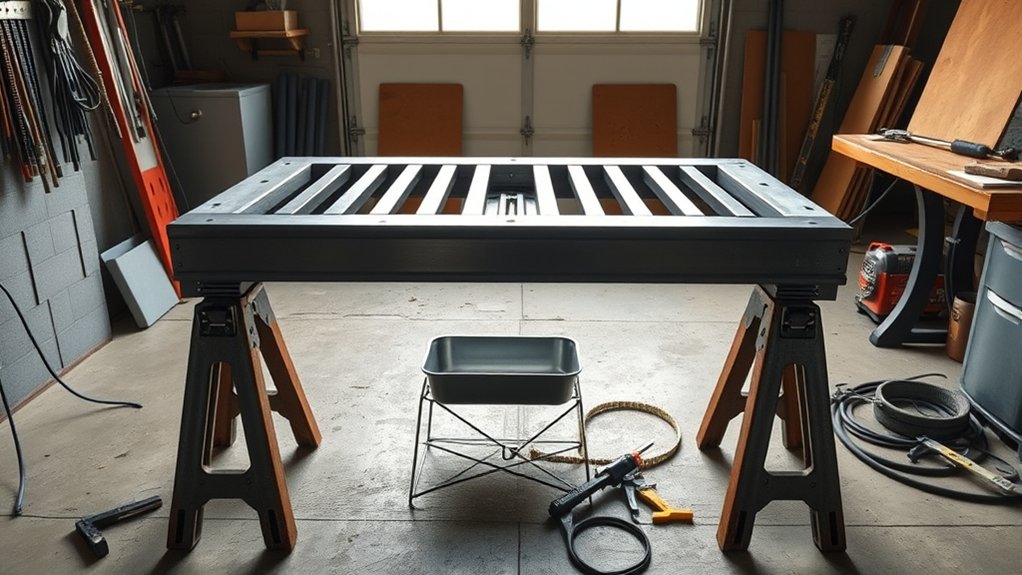
Build the base on the flattest practical surface. The frame must support the sheet, slats, pan, gantry, motors, and dynamic cutting loads without twisting the rails out of alignment.
Frame Materials and Dimensions
Two-inch square tubing with an 11-gauge wall and 2×3-inch rectangular tubing are reasonable starting materials for many personal 4×8 builds, but they are not a universal structural specification. Span, leg layout, plate weight, water load, caster design, rail position, and welding sequence all affect stiffness.
Use the larger rectangular section under long gantry tracks or other high-load spans. Place crossmembers under the slat structure and pan without blocking downdraft zones, water drainage, or debris removal.
- Clean and square tube joints on a flat reference surface
- Tack the frame in a balanced sequence before completing welds
- Recheck diagonals after each major weld sequence
- Add gussets where legs meet long rails
- Provide leveling pads at structurally supported points
- Keep rail-mounting surfaces clear of weld spatter and distortion
- Use aluminum sheet only for cool enclosure panels that are protected from direct sparks and dross
A working height of about 34–36 inches may be comfortable for loading sheets, but verify the final height with the pan, slats, rail system, gantry, torch, operator position, and material-handling method included.
Note: Welding can pull an apparently square frame out of alignment. Do not use the raw welded tube as a precision rail reference unless it has been checked, shimmed, machined, or fitted with an adjustable rail-mounting system.
Build a Removable Slat Bed
The slat bed should support full sheets while allowing the arc and molten material to pass between supports. Removable slat holders make cleanup and replacement easier.
| Component | Practical Starting Point | Purpose |
|---|---|---|
| Slat material | Replaceable mild-steel strip sized for the expected sheet load | Supports sheets and consumable parts |
| Pan material | Continuously welded mild steel with suitable bracing and drain provisions | Contains water or directs debris and air into a plenum |
| Slat spacing | Adjustable to the part size, sheet thickness, and expected drop-outs | Prevents tipping while limiting arc strikes on slats |
| Fume capture | Engineered downdraft zones or a properly designed water table | Controls smoke, sparks, and debris |
Vary slat spacing for small parts and heavy sheets. Mild-steel slats around 3/16 to 1/4 inch thick may provide useful service life on some personal tables, but the final width, depth, curve, and spacing should suit the machine load and replacement method.
Standardize the slat dimensions and keep a labeled spare set. Remove heavy slag before it bridges the gaps, blocks downdraft airflow, traps water-table debris, or prevents sheets from sitting flat.
Leveling, Casters, and Sheet Loading
Leveling feet should carry the machine during cutting. If drop-down casters are installed, retract them fully so they do not support the table in operation. Mount the caster mechanisms to reinforced plates so moving the machine does not rack the base.
A full sheet can be awkward and dangerous to load by hand. Plan for safe lifting equipment, a rolling sheet cart, removable loading supports, or another method that keeps the operator out of the gantry travel area and prevents the sheet from striking the rails.
Gantry, Z-Axis, and Motor Control Assembly
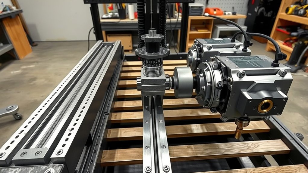
The gantry should be stiff enough to hold the torch position during acceleration but light enough for the selected motors to control without lost steps or excessive following error.
Products Worth Considering

Optoisolated input working at 5 to 24VDC or Open collector.

SCOPE OF APPLICATION: Wide clamping range, torch range from 12mm‑38mm, suitable for a variety of work scenarios

ADJUST HEIGHT : Plasma Height Control can continuously adjust the height of the cutting torch on the uneven steel plate according to the set arc pressure value , so as to ensure that the height of the cutting torch to the steel plate remains constant
Install and Align the Linear Guides
Supported linear rails, properly built V-rails, or another proven guide system can work. Mount one long-axis rail as the reference. Align the second rail to it rather than independently measuring both from a potentially distorted frame edge.
Check:
- Rail straightness and mounting-surface flatness
- Parallelism through the full travel
- Carriage preload without binding
- Gantry squareness to the reference rail
- Free travel with motors disengaged when the drive design permits it
- Clearance between bearings, fasteners, cable carriers, and hard stops
Build the Z-Axis, Floating Head, and Breakaway
The Z-axis carries the torch, initial-height sensing system, and torch height control. A floating head allows the carriage to descend until the torch or retaining cap touches the sheet and moves a switch. The controller then retracts by the calibrated switch offset to establish the surface position.
An ohmic sensing system can detect contact electrically on clean, dry, conductive material, but water, rust, paint, mill scale, and electrical noise can affect it. Many tables retain a floating switch as a backup.
Install a breakaway torch mount so a tipped part or raised slug can release the torch before the carriage or torch body is severely damaged. The breakaway should stop motion and cancel torch operation when triggered.
Configure Torch Height Control
Automatic torch height control normally performs three different tasks:
- Finds the material surface before a cut.
- Moves to the manufacturer’s pierce height and waits for the required pierce delay.
- Moves to cut height and adjusts Z position from arc voltage while the machine travels at stable cutting speed.
Do not let the THC chase voltage while the machine slows for a tight corner, small hole, end of cut, or other low-speed move. Configure anti-dive rules and use the controller and CAM system’s plasma-specific functions.
Install Motors and Drive Reduction
Stepper motors are common on personal tables because they are economical and straightforward. Servos add position feedback and can provide higher performance, but they require compatible drives, tuning, and control hardware.
Align motor shafts, couplers, pulleys, belts, racks, and pinions so the drive does not bind or load the motor bearings sideways. Set belt tension or rack preload according to the component supplier. Excessive tension can create drag and bearing wear; inadequate tension can create backlash or tooth jumping.
Bench-test the motors, drives, limit switches, home switches, emergency-stop input, floating-head switch, breakaway switch, and controller outputs before connecting the plasma trigger.
- Verify that each axis moves in the commanded direction.
- Confirm that an emergency stop removes motion permission.
- Test every limit and home input by hand at low speed.
- Confirm that a dual-drive gantry homes square.
- Check that the Z-axis stops before a mechanical crash.
- Verify the torch-start output with the plasma source disconnected.
Wiring, Grounding, and EMI Best Practices
Plasma systems create electrical noise that can reset controllers, trigger false limits, corrupt arc-voltage readings, or cause unintended commands. Electrical safety and noise control must be planned from the start.
Use Qualified Mains Wiring and Disconnects
Install the plasma source, compressor, exhaust equipment, control enclosure, and convenience circuits according to their nameplates, manuals, and applicable electrical code. Do not size a circuit from output amperage alone.
As one example, the current Powermax65 SYNC specification lists 44 A input at 240 V single phase and 9 kW. That example does not determine the branch-circuit requirements for another machine or installation. A qualified electrician should select the conductors, receptacle or disconnect, overcurrent protection, equipment grounding, and enclosure method.
Provide a nearby disconnect that can be locked out before maintenance. Disconnect power and allow stored energy to discharge before opening a plasma power supply or control enclosure.
Separate Protective Earth, Cutting Return, and EMI Bonding
Do not use “ground” to describe every conductor. The systems serve different purposes:
- Protective earth: Reduces shock risk by bonding exposed metal to the electrical grounding system.
- Cutting-current return: Carries plasma cutting current from the workpiece back to the plasma source through the work lead.
- EMI bonding and shielding: Provides controlled low-impedance paths that reduce interference in controls and signal wiring.
Follow the plasma and controller manufacturers’ grounding diagrams. Hypertherm’s grounding and shielding guidance describes a common table bus, separate component bonds, shielded signal wiring, cable separation, and a code-compliant supplemental ground rod for the systems covered by that document.
Warning: Do not install an isolated ground rod as a substitute for the building’s equipment-grounding conductor. Any supplemental electrode must be installed and bonded according to the exact equipment instructions and applicable electrical code.
Attach the plasma work lead to clean conductive material or to a manufacturer-approved cutting-current bus with a reliable path to the sheet. The work lead is not protective earth.
Route and Shield Cables
Keep torch leads, plasma input conductors, motor cables, and contactor wiring away from low-level signal, encoder, Ethernet, USB, probe, and arc-voltage cables. Use separate cable carriers or physical separation where practical.
Use twisted, shielded cable where required by the controller and plasma documentation. Shield termination rules are signal-specific; do not apply “ground one end only” to every cable without checking the manufacturer’s drawing. Bond metal control enclosures and use metal connector housings where specified.
Keep the computer and controller away from direct cutting dust. Use sealed or filtered enclosures, strain reliefs, labeled terminals, and documented wire numbers so faults can be traced safely.
Fume Management: Downdraft vs Water Table
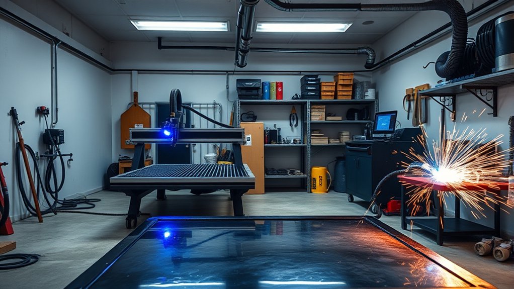
Choose the fume-control strategy before building the slat supports and pan. Plasma fumes vary with the base metal, coatings, cutting current, consumables, process gas, ventilation, and production rate.
OSHA’s welding and cutting requirements call for adequate ventilation where hazardous fumes can accumulate. A water table or downdraft system is an engineering control, but neither one makes every metal safe to cut.
Downdraft System
A downdraft table pulls smoke and fine particles down between the slats into a plenum. A full 4×8 opening may require a large fan if the entire bed is open at once, so many effective systems divide the table into zones that open near the torch position.
Do not select the fan from a universal 600–1000 CFM rule. Required performance depends on:
- Open capture area and zoned-damper design
- Required capture velocity at the cut
- Duct diameter, length, elbows, transitions, and leakage
- Filter or collector pressure loss
- Fan curve at the actual static pressure
- Cutting current, material, coatings, and production time
- Safe outdoor discharge and replacement air
- Combustible-dust and fire considerations
A downdraft system is effective only when the plume is captured at the cut. Large ductwork and a high free-air fan rating do not guarantee control after duct, hood, damper, and filter losses are added.
Use short, smooth duct runs where practical, seal the plenum, provide cleanout access, and keep accumulated slag and dust from blocking airflow. Discharge fumes only where permitted and where they cannot enter doors, windows, air intakes, or neighboring property.
Water Table
A water table captures much of the spark, slag, and particulate close to the cut. It can reduce noise and heat entering the sheet, but it also adds weight, corrosion, splash, bacterial growth, water treatment, drainage, freeze protection, and disposal requirements.
Build the pan from continuously welded steel with adequate support for the full water load. Pressure-test it before installing electronics. Keep water away from motors, connectors, drives, electrical enclosures, and operator standing areas.
Warning: Plasma cutting aluminum over or under water can generate hydrogen that becomes trapped beneath the plate and may explode. Do not cut aluminum on a water table unless the table and process have a manufacturer-supported risk assessment and a system that prevents hydrogen accumulation. Never cut aluminum-lithium alloys in the presence of water.
Do not leave a sheet covering the water table after aluminum cutting. Follow the table and plasma manufacturers’ requirements for air gaps, aeration, ventilation, water level, cleaning, and material restrictions.
Material and Coating Hazards
Carbon steel, stainless steel, galvanized steel, copper, aluminum, painted metal, plated parts, and unknown scrap can produce different fumes. Stainless steel may generate hexavalent chromium. Zinc coatings, lead paint, cadmium plating, beryllium-containing material, oils, sealants, and other coatings can create severe exposure hazards.
Identify the metal and every coating before cutting. Review the safety data sheet where available. Remove hazardous coatings only through a safe, approved process, and do not cut containers or closed parts that may contain flammable material, pressure, residue, or trapped gas.
Use source capture as the primary control. Respiratory protection should be selected as part of a proper exposure-control program; it is not a replacement for inadequate ventilation.
Recommended Build and Commissioning Sequence
- Define requirements. Record the usable cutting envelope, materials, thicknesses, production time, floor space, loading method, electrical supply, air demand, and fume-control approach.
- Freeze the component interfaces. Select the plasma source, controller, drives, motors, rails, Z-axis, THC, and CNC cable before finalizing the frame.
- Model the complete machine. Check torch reach, rail length, overtravel, cable-carrier bend radius, home positions, hard stops, pan removal, and service access.
- Fabricate the base. Tack, square, measure diagonals, weld in a balanced sequence, and recheck alignment after cooling.
- Install the pan and slat system. Confirm drainage, cleanout access, load support, slat replacement, and fume-zone operation.
- Install rails and gantry. Establish one reference rail, align the second rail, square the gantry, and verify smooth full travel.
- Install drives and Z-axis. Align belts or racks, set preload, mount the floating head and breakaway, and verify mechanical limits.
- Complete control and safety wiring. Follow the controller schematics, bond enclosures, label wiring, and test emergency-stop behavior before enabling motion.
- Perform a motion-only dry run. Leave the plasma trigger disconnected while testing motor direction, homing, limits, travel, acceleration, repeatability, and G-code motion.
- Commission air and plasma interfaces. Verify dynamic air pressure, torch-on, arc-transfer, divided voltage, probe operation, and safe work-lead connection.
- Run controlled test coupons. Start with the plasma manufacturer’s cut chart and adjust one variable at a time.
- Document the final configuration. Save controller settings, post processor, wiring diagram, material library, calibration values, maintenance log, and verified test results.
Calibration, Test Cuts, and Example Projects
Mechanical Calibration
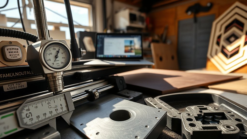
Measure the frame and gantry diagonals to check squareness. A machinist square is useful for a local check, but diagonal measurements or a large rectangular test pattern reveal error across the full bed.
Use a dial indicator or other suitable measuring method to inspect rail straightness, carriage play, backlash, and repeatability. Traverse the full table slowly and watch for changes in drag, belt tracking, rack engagement, cable tension, or motor sound.
Set steps per unit from the actual drive ratio, then command the longest practical measured move. Correct the calibration from measured travel rather than relying only on theoretical pulley or pinion dimensions. Repeat the move in both directions to check backlash and lost motion.
Home, Limit, and Emergency-Stop Tests
With the torch disabled:
- Activate each home and limit switch manually and confirm the correct input changes.
- Home the machine at reduced speed.
- Confirm that the dual-drive gantry squares consistently.
- Command travel near each software limit and verify that the machine stops before its hard stop.
- Activate the emergency stop during low-speed motion.
- Confirm that motion and torch-start permission remain disabled until a deliberate reset.
Z-Axis and Torch-Height Calibration
Calibrate Z travel, floating-switch offset, probe speed, retract distance, pierce height, cut height, and maximum correction rate. Run repeated probes at different points on a clean sheet and confirm that the reported surface position is repeatable.
Verify that the CAM post and controller use the same units and plasma sequence. A typical cut includes surface sensing, retracting by the switch offset, moving to pierce height, starting the torch, waiting for arc transfer, applying the pierce delay, moving to cut height, and then enabling height control at stable speed.
Controlled Test Cuts
Start with the plasma manufacturer’s mechanized cut chart for the exact material, thickness, amperage, consumables, gas, pierce height, pierce delay, cut height, and speed. Do not begin by guessing every setting.
Cut a simple coupon containing straight lines, an outside square, an inside square, a circle, and several holes. Measure:
- Outside and inside dimensions
- Kerf compensation
- Diagonal equality
- Hole roundness
- Edge bevel
- Top and bottom dross
- Pierce damage
- Start and stop marks
- Repeatability between identical parts
Sparks trailing below the plate can help diagnose speed, but there is no universal 15–20-degree acceptance angle. Judge the cut using the manufacturer’s chart, edge quality, dross, bevel, dimensions, arc stability, and consumable condition.
Pro Tip: Change one variable at a time and label every coupon with material, thickness, consumables, amperage, speed, pierce height, cut height, delay, and air pressure. Otherwise, a good result is difficult to reproduce.
Cut-Quality Troubleshooting
| Symptom | Likely Checks |
|---|---|
| Heavy, easy-to-remove bottom dross | Speed may be too low; verify amperage, cut height, consumables, and cut-chart settings |
| Hard, narrow bottom dross | Speed may be too high; check air flow, torch height, current, and consumable wear |
| Excessive bevel | Torch not square, incorrect cut direction, worn consumables, wrong height, air problem, or unstable motion |
| Torch dives near corners | THC remains active during deceleration; configure anti-dive or CAM path rules |
| Arc starts but motion does not begin | Check arc-transfer signal, post sequence, pierce delay, air pressure, work-lead path, and controller input mapping |
| Random resets or false limits | Inspect cable separation, shield termination, enclosure bonding, power quality, high-frequency start, damaged cables, and input filtering |
| Dimensions change across the bed | Check rail parallelism, gantry racking, lost steps, rack or belt engagement, calibration, and thermal movement |
| Short consumable life | Check wet or oily air, incorrect pierce height, excessive edge starts, double arcing, poor work connection, and wrong consumables |
Routine Maintenance
A calibrated table will not stay accurate without maintenance. Establish intervals based on cutting hours, material, fume load, and the component manufacturers’ instructions.
- Drain the compressor and separators; inspect filter restriction and dryer operation.
- Check dynamic air pressure and inspect hoses for leaks or damage.
- Inspect consumables before cut quality declines severely.
- Clean rails and racks using the component supplier’s approved method.
- Check rack preload, belt tension, pinions, couplers, fasteners, and motor mounts.
- Inspect cable carriers, flex cables, connectors, strain reliefs, and shields.
- Test the emergency stop, limits, home switches, floating head, and breakaway.
- Remove slag and fine debris before it blocks airflow or interferes with parts.
- Clean a water table, maintain its treatment system, and inspect for corrosion or leaks.
- Inspect downdraft ducting, dampers, filters, fan, discharge, and accumulated combustible debris.
- Back up software settings, material files, post processors, and machine configuration after changes.
Frequently Asked Questions
How noisy is a CNC plasma cutter in a residential garage?
Noise varies with amperage, material, air flow, table type, compressor, room surfaces, and operator position. Plasma cutting can exceed hearing-protection thresholds, and a recent NIOSH evaluation measured 85.4–102.4 dBA at a plasma-cutter control position. Use hearing protection, isolate the compressor, add suitable barriers, and measure sound at the installed operator and property-boundary positions.
What safety gear is essential beyond eye and hearing protection?
Use flame-resistant clothing, leather gloves, protective footwear, side-shield safety glasses, amperage-appropriate filtered eye or face protection, and protection from sharp sheet edges. Fume controls are essential. Respiratory protection may also be required after evaluating the metal, coatings, ventilation, and exposure. Keep an appropriate extinguisher nearby and screen the arc from other people.
Can I run a 4×8 CNC plasma table on standard household circuits?
The computer and some controls may use ordinary receptacles, but the plasma source, compressor, and exhaust equipment often require dedicated circuits. Requirements vary by model. For example, a Powermax65 SYNC is rated at 44 A input at 240 V single phase and 9 kW. Have a qualified electrician use each nameplate and installation manual to design the branch circuits, disconnects, overcurrent protection, receptacles, and grounding.
How do I control electromagnetic interference near the CNC electronics?
Choose a CNC-compatible plasma source, separate torch and power cables from signal wiring, use the specified shielded cable, bond metal enclosures, follow the manufacturer’s star-bus or grounding diagram, and keep the work-current path short and reliable. Do not guess at shield terminations or add an isolated ground rod without the equipment instructions and electrical-code review.
What insurance or permitting considerations apply to a home-built machine?
Requirements depend on the location, building use, electrical work, ventilation discharge, fire code, zoning, and whether the table is used commercially. Ask the local permitting authority which inspections apply and confirm coverage with the property insurer before installation. Keep electrical records, equipment manuals, photographs, ventilation information, and safety-control documentation.
Can I plasma cut aluminum over a water table?
Only with a table and process specifically designed to prevent hydrogen accumulation. Cutting aluminum over water can produce hydrogen that becomes trapped beneath the sheet and may explode. Follow the table and plasma manufacturers’ mitigation requirements. Never cut aluminum-lithium alloys in the presence of water.
Should I use a high-frequency-start plasma cutter on a CNC table?
A high-frequency-start source can work only when the complete machine is designed for its interference and the manufacturer approves the application. For most personal builds, a dedicated CNC source using a lower-EMI starting method is easier to integrate and less likely to cause controller resets, false inputs, or communication faults.
How much does a DIY 4×8 CNC plasma table cost?
There is no dependable single price because the plasma source, rails, drives, controller, steel, compressor, air treatment, fume system, electrical work, software, and purchased assemblies vary widely. Build a line-item bill of materials before welding the frame and include a reserve for commissioning changes, consumables, and professional electrical or ventilation work.
Conclusion
A dependable 4×8 CNC plasma table starts with a verified full-sheet cutting envelope and a realistic bill of materials. Build a rigid, level frame with serviceable slats and a properly designed pan or plenum. Match the plasma source, compressor, controls, drives, Z-axis, torch height system, electrical installation, and fume controls before fabrication locks the design in place.
Complete the machine in controlled stages. Test emergency stops, limits, homing, motion, probing, air supply, and interface signals with the torch disabled. Then use the plasma manufacturer’s mechanized cut chart for measured test coupons. Record every accepted setting and maintain the rails, air system, safety controls, fume system, consumables, and configuration files so the machine continues to cut accurately and safely.
Sources
- Hypertherm Safety and Compliance Manual — electric shock, fire, fumes, machine motion, filter shades, and aluminum water-table hazards
- Hypertherm Powermax65 SYNC Specifications — air flow, inlet pressure, input current, duty cycle, and CNC interface configurations
- Hypertherm Recommended Grounding and Shielding Practices — protective earth, cutting-current return, EMI bonding, cable separation, and shielding
- OSHA 29 CFR 1910.252 — ventilation, fire prevention, and welding and cutting safety requirements
- NIOSH Plasma and Laser Cutting Worker Safety — optical radiation, molten metal, noise, electrical, and amperage-related hazards
- LinuxCNC QtPlasmaC User Guide — current plasma-oriented machine-control, homing, limits, material, and torch-control functions