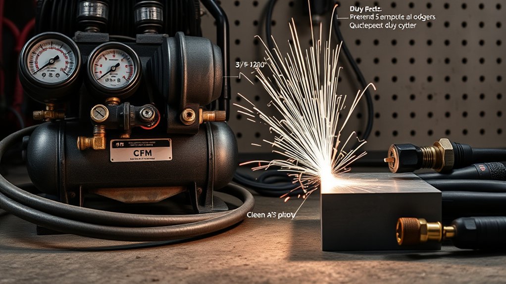
A plasma cutter can have enough electrical power and still cut badly when its air supply is undersized, wet, oily, or restricted. The right setup starts with the cutter manual: match the required airflow and inlet pressure, then confirm that the compressor, receiver, filters, regulator, hose, and couplers can hold those numbers while air is flowing.
Quick Answer
Choose an air compressor by the plasma cutter’s required airflow at its specified inlet pressure—not by tank size alone. The compressor must deliver at least that SCFM continuously, with practical reserve for pressure loss and recovery. Verify pressure while gas is flowing, and supply clean, dry, oil-free air through correctly sized filters, hose, couplers, and a regulator.
What’s in This Article
- Why Your Plasma Cutter Needs Compressed Air
- Compressor Basics and Key Specs to Check
- How to Match CFM and PSI to Your Plasma Cutter
- Tank Size, Duty Cycle, and Continuous Cut Performance
- Air Quality: Filtration, Drying, and Regulation
- Hose, Fittings, and Piping for Optimal Flow
- Power, Noise, and Portability Considerations
- How to Choose a Compressor by Workload
- Setup and Compatibility Checklist
- Common Air Supply Problems and Fixes
- Frequently Asked Questions
- Conclusion
- Sources
Key Takeaways
- Use the cutter manual’s airflow and inlet-pressure figures as the minimum requirements.
- Compare delivered SCFM at the required PSI; peak PSI, horsepower, and tank gallons do not prove that a compressor can keep up.
- A practical reserve of about 25% helps cover line loss and recovery; use more reserve for long cuts, low compressor duty cycles, or shared air lines.
- Set and check pressure while air is flowing through the cutter, not only while the system is idle.
- Use clean, dry, oil-free air or another gas specifically approved by the cutter manufacturer; never add an inline oiler.
At a Glance
| Time Required | About 20–45 minutes to verify specifications, connect the air system, check for leaks, and test dynamic pressure |
| Difficulty | Beginner to intermediate; fixed piping or electrical changes should be handled by qualified professionals |
| Tools Needed | Cutter and compressor manuals, calculator, regulator and gauge, approved hose and couplers, filter/water separator, dryer as needed, and leak-detection solution |
| Cost | No cost to verify an existing setup; hose, couplers, filtration, drying, piping, and compressor costs vary with the required SCFM and shop layout |
Why Your Plasma Cutter Needs Compressed Air
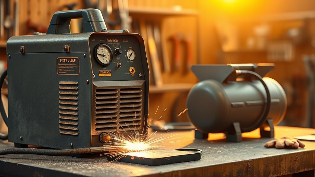
The electrical arc creates the plasma, but the gas stream constricts and shapes that arc, blows molten metal out of the kerf, and helps cool the torch. When airflow or pressure falls, the arc can become unstable and the cut may show extra dross, bevel, a wider kerf, incomplete penetration, or faster consumable wear.
Air quality matters as much as air quantity. Water, compressor oil, rust, and dirt can disturb the gas stream and contaminate the small passages in the torch. Manufacturers commonly specify clean, dry, oil-free air or nitrogen, but the exact approved gas and inlet range are model-specific.
Warning: Use only the gas approved in your cutter manual and never exceed its maximum inlet pressure. For example, the Titanium Plasma 65 manual permits clean, dry, oil-free compressed air or nitrogen and warns against oxygen, acetylene, carbon dioxide, combustible gases, and other bottled gases.
A larger tank can delay a pressure drop, but only adequate compressor output and duty cycle can sustain the cut.
Compressor Basics and Key Specs to Check
Do not choose a compressor from tank size or maximum PSI alone. Start with the cutter’s required flow and pressure, then check whether the compressor can deliver that flow for the length and frequency of your cuts.
| Specification | What It Tells You | What to Check |
| CFM or SCFM | How much air the compressor delivers | Use the delivered rating at the PSI closest to the cutter’s requirement; do not use pump-displacement CFM |
| PSI | The pressure available to move air through the cutter | Required inlet range, maximum inlet pressure, and pressure while gas is flowing |
| Tank gallons | Stored-air buffer | Enough storage to limit rapid cycling and cover short peaks; gallons do not replace missing SCFM |
| Compressor duty cycle | How long the pump may run within its stated cycle without overheating | A rating that matches repeated or continuous cutting, especially with piston compressors |
| Air quality | How much water, oil, and particulate reaches the torch | Drain, separator, filters, dryer, and maintenance requirements |
CFM and SCFM are often used loosely in consumer specifications. For comparison, use the compressor’s stated delivered output at a stated pressure, such as SCFM at 90 PSI. A compressor rated only at 40 PSI may deliver less air at 90 PSI.
Tank pressure and regulated outlet pressure are also different. The tank may store air at 150 or 175 PSI, while the regulator reduces the outlet to the range allowed by the plasma cutter.
Note: Some small plasma cutters include a built-in compressor. Those machines do not need an external air compressor for normal use, but their cut capacity and duty cycle may differ from shop-air models.
How to Match CFM and PSI to Your Plasma Cutter
Find the air requirement on the cutter data plate, specification page, or owner manual. Record both parts of the rating: airflow and pressure. A compressor that reaches the pressure but cannot supply the airflow will fall behind once the torch starts flowing gas.
Products Worth Considering
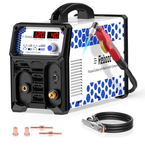
𝐁𝐔𝐈𝐋𝐓-𝐈𝐍 𝐀𝐈𝐑 𝐂𝐎𝐌𝐏𝐑𝐄𝐒𝐒𝐎𝐑, 𝐙𝐄𝐑𝐎 𝐄𝐗𝐓𝐄𝐑𝐍𝐀𝐋 𝐔𝐍𝐈𝐓𝐒 𝐍𝐄𝐄𝐃𝐄𝐃: Integrated high-efficiency air pump eliminates the need for separate air compressors. Start cutting immediately with simplified setup
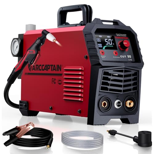
【Powerful Cutting Ability】Switch effortlessly between 110V and 220V for home or workshop use. Achieve professional 1/2" clean cuts on steel, aluminum, and copper with advanced LGBT technology. Perfect for DIY projects and heavy-duty tasks. Recommended maximum cutting thickness: 12mm @ 35A / 110V / 55 PSl; 18mm @ 50A / 220V / 75 PSI. Note: Requires compressed air (compressor sold separately).

CUTTING THICKNESS UP TO 20MM: Featuring a brand-new MCU technology upgrade, the plasma cutter machine has a high degree of internal integration, combining full digitalization for more precise control of cutting parameters such as current and voltage. This results in better cutting effects and improved stability. Cutting thickness: Quality 12mm (1/2"), maximum 20mm (3/4").
Required Flow Margin
The cutter manufacturer’s airflow figure is the minimum target. A practical planning method is:
Target compressor output = cutter airflow requirement × 1.25
That 25% reserve is not a universal manufacturer rule. It is a planning allowance for normal pressure loss, filter loading, compressor recovery, and small leaks. Consider a larger reserve—up to about 50%—when cuts are long, the compressor has a limited duty cycle, the hose run is long, or other tools share the air line.
- Compare the compressor rating at the same pressure, or at the closest published pressure above the cutter’s minimum.
- Use delivered CFM/SCFM, not peak horsepower, displacement CFM, or maximum tank PSI.
- If the compressor only barely meets the cutter’s minimum, expect more pump run time and less room for dirty filters, leaks, or hot-weather performance loss.
Optimal Pressure Range
There is no single correct PSI for every plasma cutter. Set the system within the manufacturer’s inlet range and do not exceed the stated maximum. Current examples show why a blanket “80 to 135 PSI” recommendation is too broad:
| Plasma Cutter | Official Cutting-Air Requirement | Practical Compressor Target |
| Titanium Plasma 65 | 4.2 CFM at 80–110 PSI | At least 5.3 SCFM near 90 PSI for a 25% planning reserve; about 6.3 SCFM gives a 50% reserve |
| Hypertherm Powermax85 | 6.7 SCFM at 85 PSI for cutting | About 8.4 SCFM at comparable pressure for a 25% planning reserve |
| Hypertherm Powermax105 SYNC | 9.1 SCFM at 90 PSI for cutting | About 11.4 SCFM at 90 PSI for a 25% planning reserve |
The practical targets above are sizing examples, not replacement specifications. The cutter manual remains the final authority, and compressor output must be checked at the actual operating pressure.
How to Check Dynamic Pressure
- Connect the filter, dryer, regulator, hose, and couplers you plan to use.
- Fill the compressor tank and inspect all connections for leaks.
- Use the cutter’s gas-test or purge mode. When the manual allows it, trigger the torch so air flows without making a cut.
- Adjust the regulator while air is flowing. A correct idle reading can still sag under load.
- Watch the gauge through a longer airflow test. Pressure should stay within the cutter’s allowed range as the compressor starts and recovers.
- If pressure falls, check the compressor’s delivered SCFM, dirty filters, small couplers, long hose, leaks, and regulator flow capacity.
Pro Tip: Record tank pressure, regulated pressure, and cutter-inlet pressure before and during airflow. The comparison quickly shows whether the loss is in the compressor, treatment equipment, hose, fittings, or regulator.
Tank Size, Duty Cycle, and Continuous Cut Performance
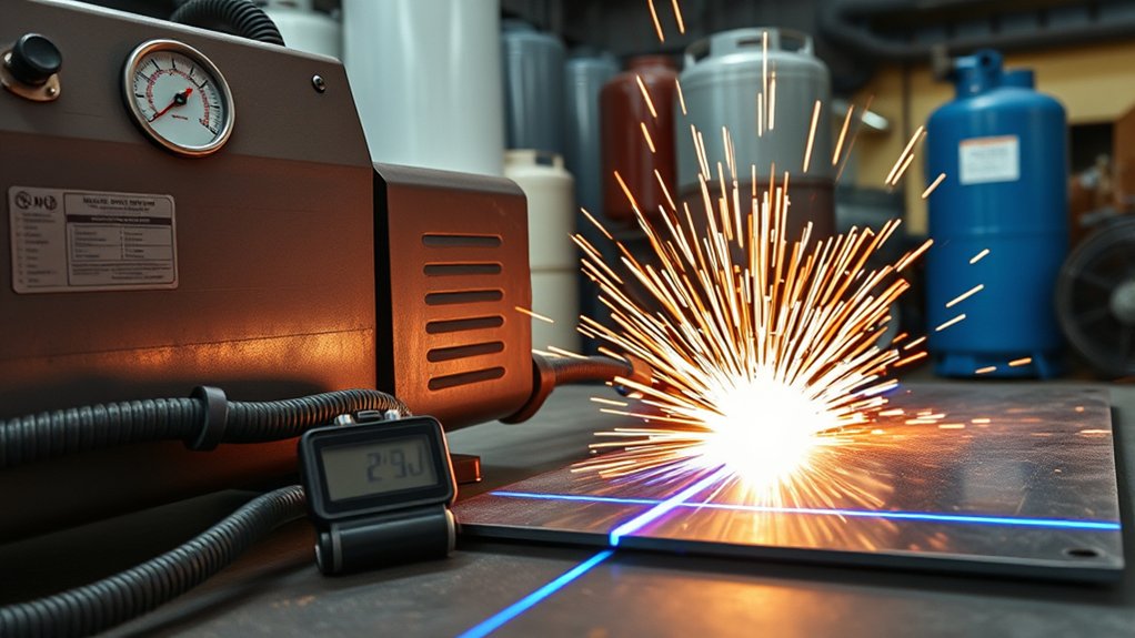
Tank capacity affects how long stored air can cover a short demand spike and how often the compressor cycles. It does not change the pump’s sustained output. A large tank attached to an undersized pump may provide a longer first cut, but pressure will still fall when average demand stays above compressor output.
Products Worth Considering
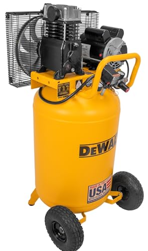
DEWALT 30 Gal., Max 175 psi Electric 6.2 SCFM at 90 psi, Single-Stage, Oil Lube, Vertical, Portable Air Compressor DXCM303.COM

[Inclusions]: This ECOMAX air compressor come with 1*1/4 in x 25 ft pvc air hose, 1* thread seal tape, 1* 1/4 fntp ball foot air chuck, 1* 1/4 npt auto plug, 1* 1/4 npt auto plug, 1* 1/4 npt auto coupler, 1* tire pressure gauge, 1* nozzle, 1* high performance blow gun and 1* sleeve.

6.3 Gallon Air Compressor: Our 1450W oil-free motor drives the compressor up to a speed of 3500 r/min and 3.35 CFM@ 90PSI air delivery. It is ideal for supporting a variety of pneumatic and air tools, such as nail gun, impact wrench, spray gun, pneumatic screwdriver, best for tire inflation, auto repair, spray painting, woodwork nailing, etc.
Tank Capacity Impact
For general receiver planning, Atlas Copco describes a starting rule of roughly 3 to 4 gallons of receiver volume per CFM, while noting that the application and compressor type matter. Applied to plasma cutting, that suggests about 18–24 gallons for a 6-CFM system or 30–40 gallons for a 10-CFM system.
Those numbers are starting points, not mandatory package sizes. A high-output compressor with a smaller receiver can outperform a low-output compressor with a 60-gallon tank. A 60-gallon stationary compressor can be convenient for repeated shop cuts, but tank size alone does not make it suitable.
- Short, occasional cuts: A smaller receiver may work when delivered SCFM meets the cutter’s demand and the pump gets adequate rest.
- Long or repeated cuts: More storage reduces rapid cycling, but the compressor still needs enough average output and duty cycle.
- Shared shop air: Size for the combined demand of tools that may run at the same time.
Compressor Duty Cycle
The compressor duty cycle and plasma cutter duty cycle are separate limits:
- Compressor duty cycle limits how long the pump or motor may run in a stated cycle before it needs cooling time.
- Plasma cutter duty cycle limits arc-on time at a stated output and ambient temperature.
A compressor can be large enough in SCFM yet unsuitable for repeated cutting if its pump is allowed to run only briefly. For regular long cuts, choose a compressor designed for a high duty cycle or continuous service and follow its cooling and maintenance instructions.
Continuous Cut Airflow
For sustained cutting, compressor delivered SCFM should meet or exceed the cutter’s actual gas use after accounting for pressure loss. The receiver covers transitions while the pump starts and recovers; it should not be the primary air source for the whole cut.
Watch how the system behaves during a test:
- If tank pressure falls steadily while the pump runs, average compressor output is below demand.
- If tank pressure is healthy but cutter pressure falls, look for restrictions, leaks, or a regulator that is too small.
- If the compressor overheats or trips, stop and compare the cutting pattern with the compressor’s duty-cycle rating.
Air Quality: Filtration, Drying, and Regulation
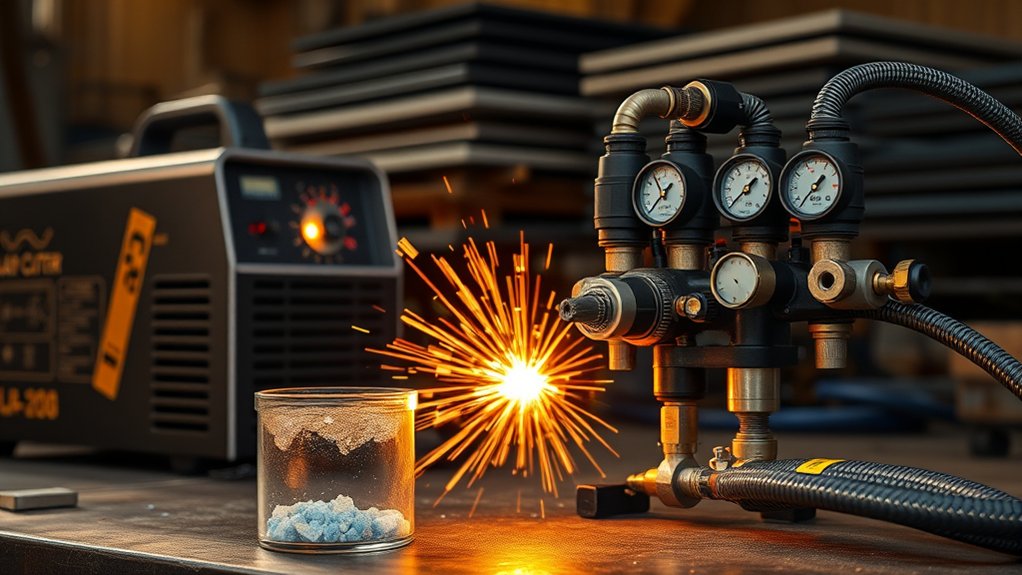
Plasma cutting needs air that is clean, dry, and free of oil at the cutter inlet. Moisture can condense in the receiver and hose, especially when hot compressed air cools downstream. Oil carryover and fine particles can also pass through basic water traps.
Recommended Air-Treatment Layout
A common small-shop layout is:
Compressor and receiver → drain or moisture separator → particulate prefilter → coalescing filter → dryer → final regulator and gauge → plasma cutter
The exact order depends on the dryer and filter design. Follow each component manufacturer’s installation instructions, including required prefilters, postfilters, airflow direction, drain position, and service intervals.
- Drain the compressor receiver and water separators often enough to prevent liquid buildup.
- Use automatic drains when the compressor runs frequently or the shop is humid.
- Install point-of-use treatment close enough to the cutter that downstream cooling does not create new condensation.
- Replace filter elements when pressure drop rises or at the maker’s service interval.
- Set the final regulator while air is flowing.
Oil-Lubricated vs. Oil-Free Compressors
An oil-lubricated compressor can supply a plasma cutter when the air-treatment system removes oil aerosols and the delivered air meets the cutter’s oil-free requirement. An oil-free compressor reduces one contamination source but still needs water and particulate control.
Do not install an inline lubricator or oiler in the branch serving the plasma cutter. If the shop uses lubricated air tools, give the cutter a separate dry, non-oiled branch.
Warning: Before opening a filter bowl, changing a hose, or servicing the air line, turn off the compressor and cutter, close the supply valve, and bleed all stored pressure. Never disable or block the receiver’s pressure-relief valve.
Hose, Fittings, and Piping for Optimal Flow
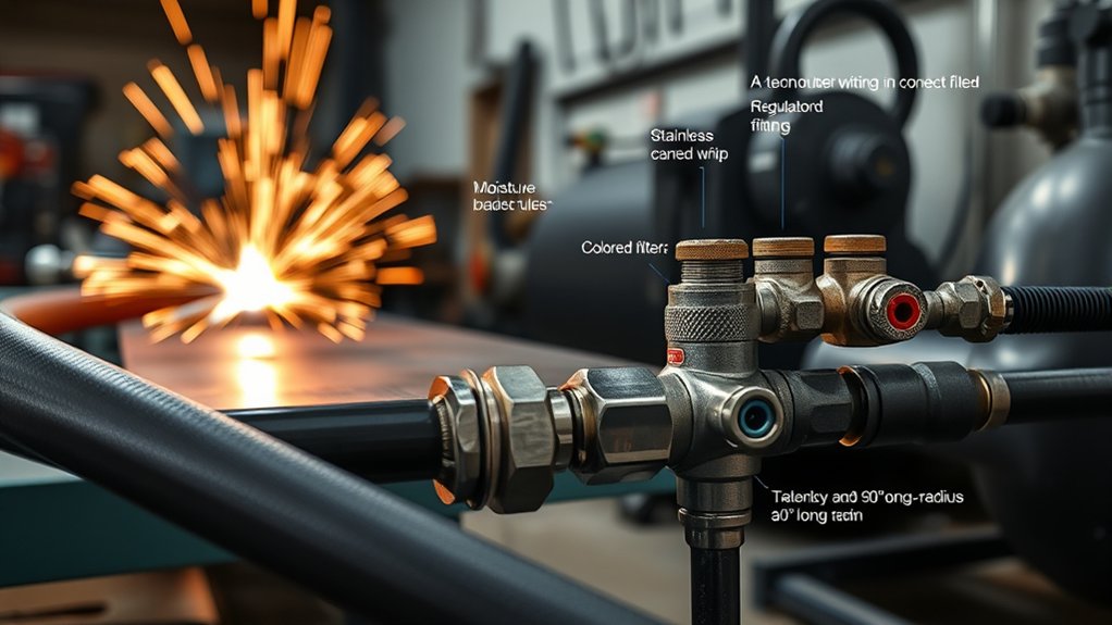
A compressor can meet the published requirement and still starve the cutter when the delivery path is too restrictive. Hose length, inside diameter, coupler bore, filter capacity, regulator size, bends, and leaks all contribute to pressure loss.
For many short shop runs in the 4–10 SCFM range, a 3/8-inch inside-diameter hose is a practical starting point. Longer runs, higher-flow cutters, and fixed piping may benefit from 1/2-inch or larger components. Treat those sizes as starting points only; the measured dynamic pressure at the cutter is the deciding test.
- Use components rated for the compressor’s maximum pressure and for at least the required airflow.
- Avoid mixing a large hose with small-bore quick-connects or a low-flow regulator.
- Keep flexible hose as short as practical and avoid kinks, crushed sections, and tight coils.
- Use approved compressed-air piping materials; do not improvise a receiver or use piping not rated for compressed air.
- Repair leaks instead of raising tank pressure to hide them.
The Compressed Air & Gas Institute states that a well-designed compressed-air system should generally keep total pressure drop between compressor discharge and point of use to no more than 10%. Small plasma setups often benefit from an even tighter margin because the cutter may have a narrow acceptable inlet range.
Power, Noise, and Portability Considerations
Power availability can limit compressor choice as much as airflow. Check voltage, phase, full-load current, plug type, and startup requirements for both machines. Do not assume a single branch circuit can start the compressor while the plasma cutter is drawing high current.
- Electrical supply: Follow both manuals. Have a qualified electrician verify circuits, receptacles, overcurrent protection, and any hard-wired installation.
- Extension cords: Avoid them when possible. If a manufacturer permits one, use only the specified wire gauge and length.
- Noise: Compare manufacturer dBA ratings measured under similar conditions. Put stationary compressors where ventilation, service access, and noise control remain safe.
- Portability: Wheels and handles help at jobsites, but a portable compressor must still meet delivered SCFM, duty cycle, and air-quality needs.
- Environment: High altitude, high ambient temperature, poor ventilation, and dirty intake air can reduce performance or shorten service life; follow the compressor’s derating and placement instructions.
How to Choose a Compressor by Workload
Choose by actual demand, not broad labels such as “20-gallon” or “60-gallon.” The cutter requirement, cut duration, compressor duty cycle, air-treatment pressure loss, and other simultaneous tools determine the correct package.
| Workload | What to Prioritize | Typical Approach |
| Light, occasional cuts | Manual minimums, portability, recovery time, basic moisture control | Delivered SCFM at or above demand, preferably with about 25% reserve; smaller receiver may work when cuts are brief and the pump rests |
| Moderate shop use | Higher duty cycle, stable dynamic pressure, larger receiver, better drying | About 25–50% airflow reserve, receiver sized for the demand pattern, full-flow fittings, and point-of-use filtration |
| Heavy, long-cut, or CNC use | Continuous output, high duty cycle, controlled dew point, low pressure drop, serviceability | A compressor engineered for sustained demand, appropriately sized receiver and dryer, dedicated branch, and measured point-of-use performance |
Also account for future tools, but do not oversize blindly. Compressor sizing guidance from Atlas Copco emphasizes matching both CFM and PSI and considering how often and how long equipment operates.
Setup and Compatibility Checklist
- Read both manuals. Record cutter airflow, inlet-pressure range, maximum pressure, approved gas, inlet fitting, and duty cycle. Record compressor delivered SCFM, duty cycle, tank pressure, and electrical needs.
- Calculate a working target. Start with the cutter’s required airflow and add a practical reserve for line loss, recovery, and your cutting pattern.
- Verify the entire air path. Make sure the separator, filters, dryer, regulator, hose, piping, and couplers are rated for the flow and pressure.
- Drain and inspect. Drain the receiver and separators, inspect the safety valve and gauges, and replace damaged hose or overdue filter elements.
- Connect without an oiler. Use clean fittings and a dedicated non-lubricated branch where possible.
- Leak-test the system. Use an approved leak-detection solution on fittings; never use your hand to feel for a compressed-air leak.
- Set pressure under flow. Use gas-test or purge mode and adjust the regulator while air is moving.
- Run an extended test. Watch cutter pressure, tank pressure, compressor run time, and recovery. Stop if pressure leaves the allowed range or the compressor overheats.
- Make a test cut. Confirm that sparks pass through the work and inspect the cut for dross, bevel, and incomplete penetration before blaming the air supply alone.
Common Air Supply Problems and Fixes
If cut quality changes suddenly, inspect the air system before changing amperage or travel speed. Air faults often appear as arc flutter, heavy dross, inconsistent bevel, incomplete cuts, pressure alarms, or unusually short consumable life.
Pressure Drops When You Start Cutting
Likely causes: Insufficient delivered SCFM, a low-flow regulator, small couplers, long or kinked hose, dirty filters, leaks, or another tool using the same line.
Fix: Compare pressure at the tank, regulator, and cutter while air flows. Service restrictions and leaks first. If tank pressure continues to fall while the pump runs, the compressor output or duty cycle is inadequate for the demand.
Water Comes Out of the Air Line
Likely causes: A full receiver drain, saturated separator, hot humid air cooling in a long hose, an undersized dryer, or missing point-of-use treatment.
Fix: Drain the receiver and separators, service the dryer, improve aftercooling or drainage, and place final moisture control near the cutter. OSHA requires air receivers covered by its standard to have drainage provisions and to be drained often enough to prevent excessive liquid buildup.
Cuts Look Rough Even With Correct Settings
Likely causes: Unstable pressure, water or oil contamination, worn consumables, wrong torch height, poor work connection, incorrect speed, or unsuitable consumables.
Fix: Verify clean dynamic air first, then inspect the electrode, nozzle, shield, work clamp, torch height, amperage, and travel speed. The Miller pre-cut checklist also recommends checking pressure after the cutter is turned on and inspecting consumables and the work connection.
The Compressor Runs Constantly or Overheats
Likely causes: Average demand above compressor output, a low allowed duty cycle, major leaks, blocked cooling airflow, high ambient temperature, or overdue maintenance.
Fix: Stop and let the compressor cool according to its manual. Repair leaks and restrictions, clean cooling surfaces, and compare the observed run time with its rated duty cycle. A larger tank alone will not correct inadequate sustained output.
Consumables Fail Early
Likely causes: Wet or oily air, incorrect pressure, poor pierce technique, excessive pilot-arc use, wrong consumables, or damaged torch parts.
Fix: Check air quality and dynamic pressure, replace overdue filter elements, inspect the torch, and follow the cutter’s consumable and pierce instructions.
Frequently Asked Questions
What size compressor do you need to run a plasma cutter?
Choose a compressor that meets the cutter’s required CFM or SCFM at the specified PSI. Add a practical reserve for pressure loss, recovery, and duty cycle. Tank size is secondary: it buffers demand, while delivered airflow determines whether the system can sustain a cut.
How much air pressure do I need to run a plasma cutter?
Use the inlet-pressure range in the cutter manual. Current machines vary: the Titanium Plasma 65 specifies 80–110 PSI, while the Hypertherm Powermax85 lists 85 PSI at its recommended cutting flow. Set pressure while gas is flowing and never exceed the model’s maximum inlet pressure.
How many CFM do I need for a plasma cutter?
The answer is model-specific. Examples range from 4.2 CFM for the Titanium Plasma 65 to 9.1 SCFM for the Hypertherm Powermax105 SYNC. Read the manual, compare compressor output at the same PSI, and add reserve based on cut length, compressor duty cycle, and line loss.
What size air compressor do I need for the Titanium Plasma 65?
Harbor Freight specifies 4.2 CFM at 80–110 PSI. A compressor delivering about 5.3 SCFM near 90 PSI provides a 25% planning reserve; about 6.3 SCFM provides a 50% reserve for longer cuts or line loss. Those reserve figures are sizing guidance, not a change to the official requirement.
Can I use a small pancake compressor with a plasma cutter?
Only when its delivered SCFM at the required PSI and its duty cycle meet the cutter’s demand. Many small pancake compressors can build enough idle pressure but cannot sustain the airflow for more than short cuts. Test dynamic pressure and recovery before relying on one.
Does a plasma cutter need an air dryer?
It needs air dry enough to meet the manufacturer requirement. A water separator may be enough in a dry climate with light use, but humid shops, long run times, and visible moisture often require refrigerated or desiccant drying plus the correct filters.
Is tank size or CFM more important for plasma cutting?
CFM at the required PSI is more important for sustained cutting. Tank size provides stored air and reduces rapid cycling, but it cannot make an undersized pump produce enough average airflow.
Can I use an oil-lubricated compressor?
Yes, when effective coalescing filtration and drying deliver clean, dry, oil-free air at the cutter. Do not use an inline oiler on the plasma-cutter branch, and service filters before pressure drop or contamination reaches the torch.
Conclusion
The right compressor is the one that delivers your plasma cutter’s required airflow at its required inlet pressure for the full cutting pattern. Start with the manual, compare delivered SCFM at the correct PSI, add sensible reserve, and verify pressure while gas is flowing.
Tank capacity helps smooth demand, but sustained compressor output, duty cycle, clean air, low-restriction plumbing, and proper regulation determine whether the arc stays stable. Build and test the whole air path, maintain drains and filters, and correct air problems before replacing torch parts or changing cut settings.
Sources
- Harbor Freight Titanium Plasma 65 Owner’s Manual — official 4.2 CFM at 80–110 PSI specification, approved gases, filtration, and safety instructions
- Hypertherm Powermax85 Specifications — official cutting airflow, pressure, and gas-quality requirements
- Hypertherm Powermax105 SYNC Specifications — official higher-output cutting airflow and pressure example
- Atlas Copco Compressor Sizing Guide — matching pressure, airflow, and duty pattern
- Compressed Air & Gas Institute: Working With Compressed Air — pressure-drop causes and system-design guidance
- OSHA 29 CFR 1910.169: Air Receivers — receiver drains, pressure gauges, and safety valves