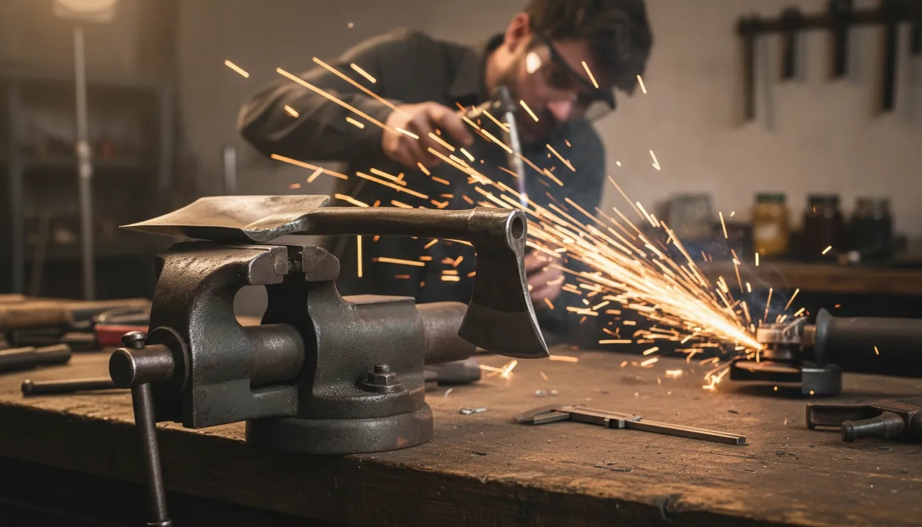
A clamp that twists, slips, or binds can ruin a clean weld setup fast. A well-built DIY pipe clamp gives you a sturdy way to hold round pipe and small square tubing without buying a costly specialty clamp.
This guide shows you how to build a rigid U-shaped frame, an aligned sliding jaw, and a threaded tightening mechanism with a thrust bearing or swivel pressure pad. You will also learn how to choose the jaw shape, plan the clamp’s opening, control weld distortion, test the finished tool, and use it safely.
Quick Answer
Build a DIY pipe clamp with a rigid welded-steel frame, two parallel guides, a square sliding jaw, and a coarse-thread screw that pushes through a thrust bearing or swivel pad. Use V-shaped contact faces for round pipe, keep every moving part aligned, tack before final welding, and test the clamp only on scrap material first.
Key Takeaways
- Size the frame, jaw opening, screw travel, and throat depth around the tubing you actually plan to hold.
- Use known weldable steel instead of unidentified scrap, coated hardware, or unknown rebar.
- Use a V-shaped jaw or removable V-pad for round pipe and broad flat faces for square tubing.
- Keep both guide rods parallel and the screw centered so the moving jaw does not twist or bind.
- Use a thrust bearing, thrust washer, or swivel pressure pad designed to carry axial screw force.
- Tack everything first, check movement, and alternate final welds to limit heat distortion.
- Never use a homemade clamp for lifting, suspension, structural support, or any task that requires a certified working-load limit.
At a Glance
| Time Required | About 2 to 4 hours, plus cooling and adjustment time |
| Difficulty | Intermediate metal fabrication and welding |
| Tools Needed | Welder, angle grinder, drill, square, measuring tools, temporary clamps, flat work surface, and suitable PPE |
| Cost | Varies; lowest when suitable weldable steel offcuts and matching hardware are already available |
What’s in This Article
- What this DIY pipe clamp does
- Plan the clamp size and jaw shape
- Tools and materials you’ll need
- How long this build takes
- Key design choices for a strong, non-slipping clamp
- Step-by-step build
- How to test clamping strength and prevent slip
- Troubleshooting a DIY pipe clamp
- Common mistakes and how to avoid them
- Maintenance and storage
- Safety notes for welding and testing
- Frequently asked questions
- Takeaway
- Sources
What This DIY Pipe Clamp Does
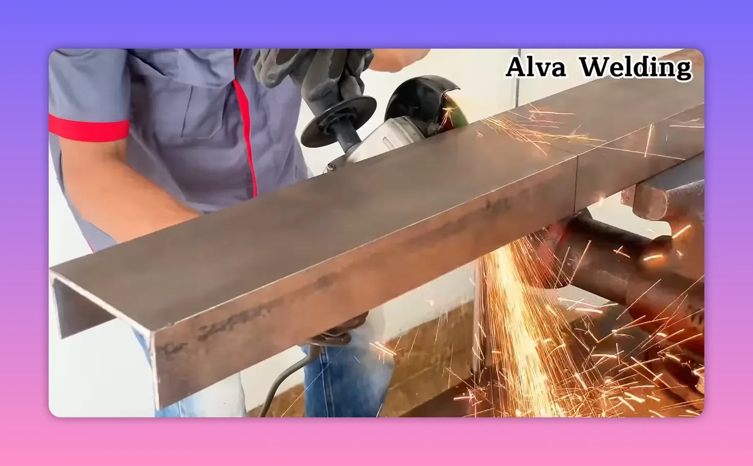
This clamp uses three main systems to hold tubing steady:
- Rigid frame: A U-shaped welded-steel frame carries the reaction force and limits jaw spreading.
- Sliding jaw: A moving jaw travels on two straight, parallel guides so it closes without twisting.
- Threaded screw: A threaded rod or screw converts handle torque into linear clamping force.
You can use the finished clamp for common fabrication tasks such as:
- Positioning round pipe and small square tubing during welding
- Holding parts in alignment while you place tack welds
- Keeping a workpiece steady during measuring, fitting, or light fabrication
- Holding two compatible pieces while you check angle and gap
Note: This is a workholding tool, not an engineered lifting device. Its safe force cannot be known from appearance alone because capacity depends on the steel, frame geometry, screw, welds, guides, and workmanship.
Plan the Clamp Size and Jaw Shape
Decide what the clamp must hold before cutting steel. A clamp for 25 mm square tubing does not need the same opening, throat depth, frame stiffness, or jaw width as one intended for large pipe.
Choose the maximum jaw opening
Measure the largest outside diameter or tube width you plan to hold. Add enough extra travel to insert and remove the workpiece easily. The screw must be long enough to cover the full opening without leaving too little thread engaged in the nut.
Choose the throat depth
Throat depth is the distance from the front of the jaws to the inside of the frame. A deeper throat reaches farther onto the workpiece, but it also increases leverage on the frame. Keep the throat only as deep as the intended work requires.
Match the jaw to the workpiece
- Round pipe: Use a welded V-block, shallow saddle, or removable V-pad. Commercial pipe clamps use V-shaped contact to stabilize round stock and reduce side-to-side movement.
- Square tubing: Use broad, flat, parallel faces that spread pressure across the tube wall.
- Thin-wall tubing: Use wider, smoother pads and moderate hand pressure to avoid denting or crushing the workpiece.
For an example of V-pad contact on a purpose-built pipe clamp, see the Strong Hand Tools pipe-pliers design.
Treat the sample dimensions as a starting point
The original concept uses a frame length of about 35 cm and two guide pieces of about 8 cm each. Those measurements are examples, not universal specifications. Increase or reduce them only after checking the required opening, throat, guide support, and frame stiffness.
Tools and Materials You’ll Need
Products Worth Considering

Trusted Quality: Backed by over a decade of professional expertise in automotive repair tools, our products are chosen by numerous technicians and DIY enthusiasts.

Zero-Wobble 1" to 2.5" Pipe Fit-Up Clamp: Securely clamps all pipes from 1 to 2.5 inches (25.4-63.5 mm). Unlike standard clamps that feel loose, our anti-slip wide grip plates ensure a perfectly balanced, gap-free hold for precision alignment regardless of pipe wall thickness.

Suitable for Various Pipe Sizes: The pipe welding vise accommodates a wide range of pipe diameters, from 1/2 inch to 8 inches.
Materials
- Known weldable steel for the frame: U-channel, rectangular tube, plate, or bend-fabricated mild steel sized for the planned jaw opening and throat
- Two straight guide rods or heavy-wall guide tubes: About 8 cm each in the example design, with enough supported length to prevent jaw rotation
- Close-fitting guide sleeves or bushings: Attached to the movable jaw so it can slide on both guides
- Coarse-thread steel rod or screw: Long enough for the full jaw travel with adequate thread engagement
- Matching nut, coupling nut, or threaded block: Clean, undamaged, and correctly matched to the screw
- Thrust bearing or thrust washer: Used where the rotating screw transfers axial force
- Swivel pressure pad: Optional but useful because it lets the screw rotate while the pad stays against the movable jaw
- Steel washers: Used to provide flat, centered bearing seats
- Fixed and movable jaw pieces: Flat plate, angle, or fabricated V-jaw parts
- Handle: A sliding crossbar, welded bar, or tube sized for controlled hand tightening
- Angle iron or structural steel: Used to reinforce the upper jaw and other concentrated-load areas
- Known weldable steel bar: Used for compact links, stops, or jaw supports
Warning: Do not assume unidentified rebar is suitable welding stock. Reinforcing bar is manufactured under several different specifications. Prefer known weldable mild steel, or identify the bar and use an appropriate welding procedure. See the CRSI overview of reinforcing-bar specifications.
Tools
- Angle grinder with the correct guard, handle, cutting wheel, and grinding wheel
- Drill, suitable drill bits, center punch, and cutting fluid when appropriate
- Tape measure, calipers, combination square, and straightedge
- MIG, TIG, or stick welding machine suitable for the steel thickness
- Temporary clamps, magnets, spacers, and a flat welding surface
- Wire brush, deburring tool, and file
- Welding helmet, safety glasses, gloves, hearing protection, suitable clothing, and task-appropriate respiratory controls
How Long This Build Takes
Plan on about 2 to 4 hours for layout, cutting, fitting, tack welding, final welding, grinding, assembly, and testing. The actual time depends on your steel sizes, welding process, available tools, and how much correction the guides or jaws need.
Allow extra time for the parts to cool naturally between welding and alignment checks. A slow tack-and-check process is usually faster than cutting apart a frame that was fully welded out of square.
A clean tack weld holds the guide tubing in position and helps the sliding jaw move smoothly later.
Key Design Choices for a Strong, Non-Slipping Clamp
Products Worth Considering

Impressive Press: This bearing clamp installs bearing cups on U joints; Use the pressure of the forcing bolt to provide clearance for the insertion of the retaining rings

FITS STARLINK MINI 2025 & 2026: The precision-CNC aluminum adapter snaps directly into both the 2025 and 2026 Starlink Mini base — both versions share the same connector, so one adapter covers either model. No guessing which version you need.
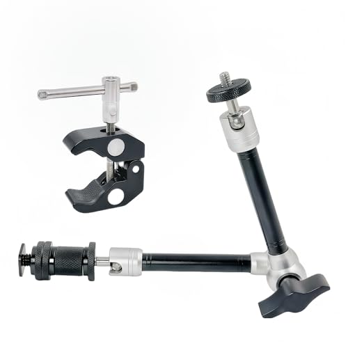
Versatile Magic Arm with Super Clamp: Designed with dual articulating arms and a 360° friction gear joint, this 11"/28cm magic arm securely mounts monitors, LED video lights, DSLR/mirrorless cameras, mics, and accessories compatible with GoPro Hero 12–7, Insta360, DJI Osmo Action, and more.
Use rigid frame geometry
The U-shaped frame must carry the reaction force without permanently spreading. Stiffer steel sections, shorter unsupported spans, gussets, and a limited throat depth all help reduce flex.
There is no single safe frame thickness for every homemade clamp. If the frame visibly opens, twists, or remains bent after a light test, stop using it and redesign the frame.
Keep both guides parallel
The guide rods must be straight, parallel, and square to the jaw faces. The sleeves on the movable jaw should slide freely without enough clearance to let the jaw rock.
Use temporary spacers or a simple alignment jig while tacking the guides. Check the distance between the guides at both ends before completing the welds.
Keep the screw centered
The screw axis should push near the center of the movable jaw. An off-center screw can tilt the jaw, overload one guide, and make the mechanism bind.
Pro Tip: Thread the screw through the nut and temporarily position the movable jaw before welding the nut support. The assembled screw acts as an alignment reference and makes an off-axis nut easier to spot.
Use a thrust bearing or swivel pressure pad
The screw pushes along its own axis, so the bearing or washer stack must be suitable for axial force. SKF describes thrust ball bearings as bearings intended for axial loads.
Do not place a bearing where weld heat or spatter can damage it. Fit the bearing after welding and cooling, or shield the bearing and machined surfaces during nearby work.
Use enough thread engagement
The screw should remain fully supported by the nut or threaded block throughout the useful travel. Avoid running the clamp with only a few threads engaged. Replace parts with stripped, flattened, badly rusted, or cross-threaded threads.
Protect the workpiece from concentrated pressure
A small contact point can dent thin tubing before the clamp frame reaches its limit. Use broad pads for thin-wall material and tighten only enough to hold the work securely.
Step-by-Step Build: Practical Welding Workflow
Exact dimensions change with the steel and tubing you plan to clamp. Use the following order to keep the frame, guides, screw, and jaws aligned.
Step 1: Lay out the clamp before cutting
- Place a sample of the largest pipe or tube on the work surface.
- Mark the planned maximum jaw opening and throat depth.
- Mark the frame centerline, guide positions, jaw faces, and screw axis.
- Confirm that the handle will have room to turn without hitting the frame or workbench.
Step 2: Cut and fit the U-shaped frame
- Cut the U-shaped steel to your planned length, such as about 35 cm for the example build.
- Deburr every cut edge.
- Remove rust, paint, plating, oil, and heavy mill scale from the weld zones using a safe method for the coating involved.
- Set the frame on a flat surface and check that it does not rock or twist.
- Mark the guide, fixed-jaw, reinforcement, and screw-support locations.
Step 3: Install the guides for the sliding jaw
- Cut two guide pieces, such as 8 cm each for the example design.
- Deburr the guide ends and clean the surfaces.
- Position the guides parallel to each other and square to the planned jaw faces.
- Use equal spacers or a temporary jig to hold the guide spacing.
- Place small tack welds on opposite sides.
- Recheck spacing, height, and parallel alignment before adding more weld.
- Alternate short welds and allow cooling to reduce weld pull.
The threaded rod and nuts sit between the clamp parts so you can check that the tightening mechanism lines up with the jaws.
Step 4: Build the screw-driven tightening section
- Select a nut, coupling nut, or threaded block that exactly matches the screw.
- Clean the screw and run it through the threads by hand before welding.
- Position the nut so the screw centerline meets the center of the movable jaw.
- Protect exposed threads from weld spatter with a removable shield or suitable anti-spatter protection.
- Tack the nut support in place.
- Remove the screw when possible before completing nearby welds so heat and spatter do not damage it.
- After cooling, reinstall the screw and confirm that it turns freely.
Step 5: Assemble the fixed and movable jaws
- Cut steel pieces for the fixed jaw and movable jaw.
- Attach close-fitting sleeves or bushings to the movable jaw.
- Slide the movable jaw onto both guides and check for free movement.
- Square the movable jaw to the fixed jaw.
- Use flat contact faces for square tubing or fabricate a V-shaped contact face for round pipe.
- Tack the jaw parts before completing the welds.
- Close the clamp by hand and confirm that both jaw faces contact evenly.
Tightening hardware stays in place while you check alignment before final welding.
Step 6: Add the thrust bearing and pressure pad
- Create a flat, centered seat at the end of the screw or on the movable jaw.
- Install a thrust bearing or thrust washer in the correct load direction.
- Add hardened or suitable steel washers where needed to support the bearing races.
- Fit a swivel pressure pad if you want the screw to rotate without scuffing the jaw.
- Retain the bearing and pad so they cannot fall out while the clamp is open.
- Turn the screw by hand and confirm that the rotating and stationary parts do not rub the frame.
Step 7: Reinforce the top jaw structure
- Place angle iron, plate, or a gusset where the jaw load concentrates.
- Keep reinforcement clear of the guides, screw, handle, and full jaw travel.
- Tack the reinforcement in several places.
- Close the clamp by hand and check that the jaw faces still meet evenly.
- Alternate the final welds to limit heat distortion.
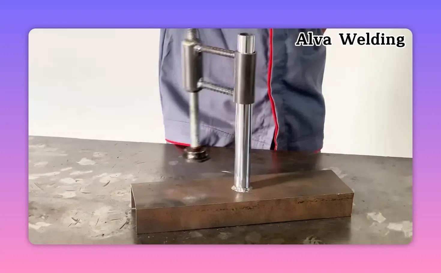
Step 8: Add the handle
- Drill or fabricate the screw end for a sliding crossbar, fixed T-handle, or other controlled hand grip.
- Round the handle ends or add stops so the bar cannot slide out unexpectedly.
- Keep the handle short enough that normal hand force does not encourage excessive torque.
- Do not design the handle to accept a pipe extension or cheater bar.
Step 9: Finish, clean, and reassemble
- Remove sharp edges, burrs, and weld spatter.
- Clean the screw threads and guide surfaces.
- Apply a light lubricant to the screw, thrust surfaces, and guides unless the lubricant could contaminate the planned welding work.
- Keep lubricant off the jaw contact faces.
- Apply a suitable corrosion-resistant finish to non-contact surfaces after final inspection.
- Reassemble the clamp and run it through its full travel by hand.
How to Test Clamping Strength and Prevent Slip
Test the clamp on scrap tubing before trusting it on a real fabrication project. Wear eye protection and keep your hands out of the line between the jaws.
- Check unloaded movement: Open and close the clamp through its full travel. The jaw should not stick, tilt, or scrape heavily.
- Check jaw contact: Close the jaws lightly on a flat coupon or sample tube. Look for even contact rather than one corner touching first.
- Check round-pipe seating: Place round scrap in the V-jaw and confirm that it stays centered as pressure increases.
- Increase pressure gradually: Tighten by normal hand force only. Do not strike the handle or add an extension.
- Watch the frame: Stop if the frame spreads, twists, or stays bent after release.
- Watch the workpiece: Stop if thin tubing dimples, buckles, or changes shape.
- Check the welds: Look for cracking, tearing beside the weld, or movement at a joint.
- Check holding ability: Try to rotate or slide the scrap by hand without placing your body in the release path.
- Release and inspect: Open the clamp and confirm that the screw, bearing, guides, and jaw remain aligned.
If the clamp slips, do not simply apply more torque. Improve the jaw shape, increase the contact area, clean oil from the contact surfaces, and correct any screw or jaw misalignment.
Troubleshooting a DIY Pipe Clamp
| Problem | Likely Cause | Fix |
| Sliding jaw binds | Guides are not parallel, a sleeve is distorted, or the screw pushes off-center | Measure both guide spacings, check sleeve fit, correct weld pull, and recenter the screw |
| Screw is difficult to turn | Damaged threads, weld spatter, poor lubrication, or an incorrect bearing seat | Clean and inspect the threads, repair or replace damaged parts, and realign the thrust components |
| Round pipe slips sideways | Flat jaws, shallow contact, oil, or jaw misalignment | Add a V-pad or saddle, clean the contact area, and square the jaws |
| Jaw tilts under pressure | Guides are too close together, too short, loose in the sleeves, or unevenly loaded | Increase guide support, improve sleeve fit, widen guide spacing, or center the pressure point |
| Frame spreads permanently | The frame is too flexible or has been overtightened | Stop using the clamp, replace or redesign the frame, reduce throat depth, and add suitable reinforcement |
| Thin tubing dents | Contact area is too small or pressure is excessive | Use wider pads and less pressure; support the tube internally when appropriate |
Common Mistakes and How to Avoid Them
Rushing the tack welds
Tack the frame, guides, nut support, and jaws first. Check squareness and movement after every group of tacks. Completing one side before checking the other can lock distortion into the assembly.
Skipping reinforcement where the load is highest
The frame can flex if the fixed-jaw area or screw support is too light. Add reinforcement without blocking jaw travel or creating a new stress concentration.
Welding the guides out of line
Crooked or warped guides make the sliding jaw feel jerky. Use equal spacers, short opposing welds, and repeated measurements while the parts cool.
Using the wrong type of bearing
A random bearing may not support the screw’s axial load. Use a thrust component with flat, centered seats and follow the bearing manufacturer’s load-direction instructions.
Welding with the bearing or screw exposed
Weld heat, grit, and spatter can damage threads and bearing surfaces. Remove these parts before final welding when possible, or shield them completely.
Using smooth flat jaws on round pipe
Round material can roll or squeeze sideways between flat faces. Use a V-shaped jaw, saddle, or removable V-pad.
Applying more torque instead of fixing the geometry
A longer handle may hide poor jaw contact or frame flex until something bends or breaks. Correct the contact, alignment, and stiffness rather than adding a cheater bar.
Maintenance and Storage
- Brush dust, slag, and metal chips from the guides and screw after use.
- Inspect the screw, nut, thrust bearing, handle, guides, jaw pads, and welds before each major job.
- Apply a light lubricant to clean threads and sliding guides when it will not contaminate the workpiece.
- Keep oil and grease away from the jaw contact faces.
- Replace damaged bearings, stripped threads, bent handles, cracked welds, or worn jaw pads.
- Store the clamp dry with light pressure released from the screw.
- Do not continue using a frame that has permanently opened, twisted, or cracked.
Safety Notes for Welding and Testing
Warning: Welding and grinding can cause fire, burns, eye injuries, electric shock, noise exposure, flying fragments, and harmful fume exposure. Use equipment only when you understand its instructions and can control the hazards in your work area.
Prepare a fire-safe work area
OSHA’s welding and cutting requirements call for hot work to be performed in an area that is or has been made fire-safe. Move combustible material at least 35 feet away when practical, or protect it from sparks, slag, and heat. Keep suitable fire-extinguishing equipment available and use a fire watch when conditions require one.
For hot work, combustible material within 35 feet should be removed when practical or protected from sparks, heat, and slag.
Use the grinder correctly
- Keep the correct grinder guard installed and positioned between you and the wheel.
- Use a wheel made for the operation and rated for at least the grinder’s maximum speed.
- Inspect the wheel, flange, nut, guard, cord, and side handle before use.
- Disconnect power or remove the battery before changing wheels.
- Stand clear during startup and use two hands when the tool is designed for a side handle.
See OSHA 1910.243 for portable-tool and abrasive-wheel guarding requirements.
Identify the metal and coatings
Do not weld unknown, painted, plated, galvanized, stainless, lead-coated, or cadmium-containing metal until you have identified the material and chosen appropriate controls. Welding-fume risk changes with the base metal, filler, coating, process, and ventilation. NIOSH notes that fumes from stainless steel and metals or coatings containing zinc, lead, cadmium, nickel, chromium, and copper can present greater hazards than ordinary mild-steel welding fumes.
Review the NIOSH welding-fume and extraction guidance before welding coated or unfamiliar material.
Control fumes at the source
- Keep your head out of the fume plume.
- Use effective general ventilation and local exhaust positioned close enough to capture fumes without disrupting shielding gas.
- Do not weld in a confined space without a suitable confined-space and ventilation plan.
- Do not rely on an ordinary dust mask for welding fumes.
- When respiratory protection is required, use properly selected equipment under an appropriate respiratory-protection program, including medical evaluation and fit testing where applicable.
Wear task-appropriate PPE
- Welding helmet with a suitable filter shade
- Safety glasses with side protection under the helmet
- Welding gloves and flame-resistant clothing
- Closed footwear suitable for hot metal and sparks
- Hearing protection for grinding and other noisy work
- Face protection appropriate to grinding and wire-wheel hazards
Test conservatively
- Let welded parts cool before assembly or testing.
- Use scrap material for the first tests.
- Keep fingers away from the jaws, guides, and screw-pad pinch points.
- Increase pressure slowly using normal hand force.
- Do not hammer the handle or add a cheater bar.
- Stop if the frame, screw, jaws, guides, or workpiece begin to deform.
- Do not use the clamp to lift, suspend, hoist, secure overhead loads, support a vehicle, or replace a certified structural clamp.
Frequently Asked Questions
What size threaded rod should you use for a DIY pipe clamp?
There is no universal safe size. The screw must match the planned jaw opening, expected hand torque, frame stiffness, nut length, and workpiece. Use known steel with clean, matching threads and enough engagement throughout the clamp’s travel. Do not compensate for an undersized frame by fitting an oversized handle.
Why does a thrust bearing make the clamp feel stronger?
A thrust bearing does not increase the strength of the frame or welds. It reduces friction where the rotating screw transfers axial force, so tightening feels smoother and more of your hand effort reaches the jaw. The bearing must be installed on flat seats and in its correct load direction.
Will this clamp work on both round pipe and square tubing?
Yes, if the jaw contact suits the shape. Use a V-shaped jaw, saddle, or removable V-pad for round pipe. Use broad, flat, parallel faces for square tubing. Thin-wall material needs wider pads and less pressure to prevent denting.
What’s the best way to check alignment before final welding?
Assemble the clamp with small tack welds. Use a square and straightedge to check the jaw faces, measure the guide spacing at both ends, and turn the screw by hand while watching the movable jaw. Finish welding only after the jaw travels freely and closes evenly.
What should you do if the sliding jaw binds when tightening?
Check for guide warping, unequal guide spacing, tight or distorted sleeves, weld spatter, and an off-center screw. Correct the alignment rather than forcing the handle. Grinding, reaming, replacing a sleeve, or carefully re-welding the guides may be required.
How can you improve grip so the clamp doesn’t slip?
Clean oil and debris from the jaw faces, correct jaw misalignment, and match the jaw shape to the workpiece. Add a shallow V-pad for pipe or a replaceable textured pad for flat material. Avoid sharp teeth that can cut or collapse thin tubing.
Can you use rebar to build the clamp?
Known weldable mild-steel bar is a better default. Rebar is produced under several specifications, and unidentified scrap may require different welding procedures. Use rebar only when you can identify the material and confirm that your welding process is suitable.
Can a homemade pipe clamp be used for lifting?
No. This design has no certified working-load limit, proof test, safety factor, or lifting-device approval. Use it only as a stationary workholding clamp. Never use it to hoist, suspend, support, or secure a load above people or equipment.
Takeaway
A strong DIY pipe clamp depends on more than heavy steel. The frame must stay rigid, the guides must remain parallel, the sliding jaw must close squarely, and the screw must push through a suitable thrust surface. V-shaped contact improves round-pipe grip, while broad flat pads protect square and thin-wall tubing.
Build slowly, tack before final welding, protect the screw and bearing from heat and spatter, and test the clamp on scrap with normal hand force. Once it closes smoothly and holds without slipping, tilting, crushing the workpiece, or permanently spreading the frame, it can become a useful workholding tool for cleaner fabrication setups.
Sources
- OSHA 1910.252 — Welding, Cutting, and Brazing — fire prevention, ventilation, PPE, and hot-work safety
- OSHA 1910.243 — Guarding of Portable Powered Tools — portable grinder and abrasive-wheel guarding
- NIOSH — Welding Fumes and Fume Extraction Guns — fume hazards and source-capture ventilation
- SKF — Thrust Ball Bearings — bearing selection for axial loads
- Strong Hand Tools — Large Diameter Pipe Pliers — V-pad contact for holding round pipe
- Concrete Reinforcing Steel Institute — Rebar Properties — reinforcing-bar specifications and material identification