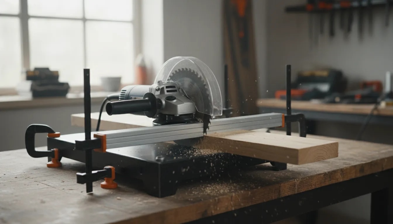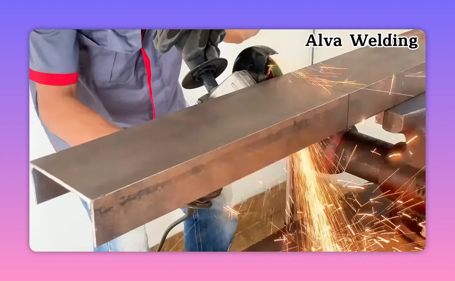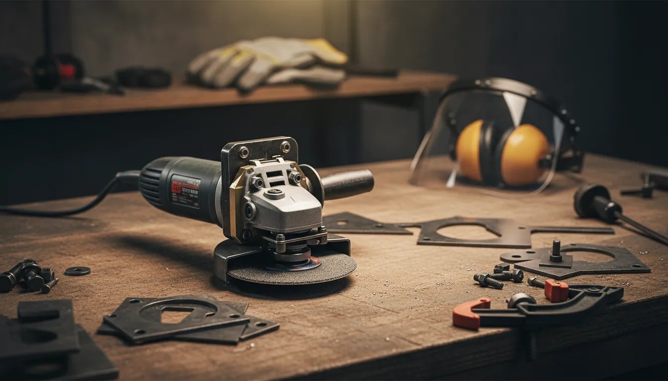
An angle grinder can cut, grind, strip, sand, and polish, but an adapter can add hazards that the grinder was never designed to control. A DIY angle grinder adapter must not be treated as a simple part that makes two mismatched components fit. It must preserve the correct guard, flange support, spindle engagement, accessory speed rating, grip, balance, and intended direction of force.
The safest choice for any rotating wheel, disc, brush, or pad is the adapter or mounting system approved by the grinder and accessory manufacturers. Shop-made work is better limited to non-rotating guides, brackets, stands, and dust-shroud mounts that do not alter the wheel-retention system. This guide explains how to judge the risk, verify compatibility, build only within a safe scope, and reject an adapter that cannot be proven suitable.
Quick Answer
A DIY angle grinder adapter may be a hub, plate, bushing, bracket, or guide, but manufacturer-approved parts are the safest choice for anything that rotates at grinder speed. A usable setup must match the spindle, arbor, flanges, guard, rotation, load direction, wheel size, and RPM rating without wobble or improvised hardware.
Key Takeaways
- Prefer manufacturer-approved hubs, backing pads, flange sets, guards, and adapters for every rotating accessory.
- Do not use an accessory merely because it can be threaded or clamped onto the grinder. Speed, support, guard type, size, and load direction must also match.
- Unplug a corded grinder or remove the battery before measuring, mounting, adjusting, or inspecting an adapter.
- Reject any setup that wobbles, slips, blocks the guard, side-loads a cut-off wheel, alters the factory flanges, or uses damaged or improvised hardware.
- Test in stages: inspect, hand-spin, check runout, perform a guarded no-load run, apply a light load, and inspect again.
At a Glance
| Time Required | Allow at least 30–60 minutes for research, measuring, and mock-up; machining, welding, inspection, and correction can take several hours |
| Difficulty | Intermediate for a non-rotating guide or bracket; advanced and often unsuitable for DIY fabrication if the part carries an accessory at grinder speed |
| Tools Needed | Grinder and accessory manuals, calipers, thread gauge, square, suitable torque tool, clamps, deburring tools, PPE, and a dial indicator when checking a rotating hub |
| Cost | Varies by design; a manufacturer-approved adapter may cost less than correctly machining, guarding, inspecting, and rebuilding a custom rotating assembly |
Warning: Do not fabricate a rotating wheel hub merely because you can match the thread. A part spinning at grinder speed can fail without much warning. Use the grinder manufacturer’s approved flanges, nuts, hubs, backing pads, and guards unless the complete custom system has been designed and verified by a qualified professional for that exact grinder and accessory.
What an angle grinder DIY adapter actually does
An adapter is a custom-made or selected interface that connects a grinder to an accessory, guide, fixture, shroud, or mounting system. Depending on the design, it can:
- Change the spindle interface to match a compatible and approved accessory or hub.
- Support a guide or fixture so repeated cuts or sanding passes are easier to control.
- Improve alignment and stability when every mounting face is square, rigid, fully seated, and correctly fastened.
- Help with repeatability by reducing hand-only variation during cutting, polishing, wire brushing, sanding, or sharpening.
The adapter can make a general-purpose grinder more task-specific, but it must not force an unsafe accessory onto the spindle or replace a safety feature built into the tool. A physical fit alone does not prove that the accessory is suitable.
Warning: Do not use a DIY adapter that prevents the correct guard from fitting. For covered workplace use, OSHA 1910.243 requires guards on portable abrasive-wheel tools and states that a right-angle grinder guard must be positioned between the operator and the wheel. Home users can also treat this as a strong minimum safety baseline.
Who should use a grinder adapter and who should not
An adapter project may make sense when an experienced fabricator needs a non-rotating guide, body clamp, shroud mount, or fixture that is not sold for the exact setup. It is a better fit if you:
- Understand how the grinder’s guard, spindle, flanges, wheel lock, switch, and side handle work.
- Have the grinder model number and its current instruction manual.
- Can identify thread size, pitch, arbor size, flange contact, accessory size, and clearance accurately.
- Can fabricate and inspect parts without weak welds, loose hardware, sharp burrs, flexible plates, or off-center seating.
- Can stop the project when the design would alter the factory wheel-retention system.
You should avoid a DIY adapter if you cannot reliably:
- Maintain concentric alignment, meaning the rotating part shares the same centerline as the grinder spindle.
- Keep the factory guard or correct accessory-specific guard installed and correctly positioned.
- Confirm the spindle size, thread pitch, arbor fit, accessory size, and RPM rating.
- Determine whether the accessory is designed for edge loading, face loading, or both.
- Use a secure retention method that will not loosen from rotation, vibration, heat, or repeated starts.
- Inspect and test the setup without placing yourself or anyone else in the fragment path.
If any of these checks are uncertain, use the correct manufacturer-approved accessory, guard, backing pad, flange set, or purpose-built tool instead.
Common adapter types and safer use cases
Adapter risk depends largely on whether the custom part remains stationary or spins with the accessory.
- Manufacturer-approved spindle or thread adapters: These change how a listed accessory attaches to a compatible grinder. They must match the specified spindle thread, shoulder, flanges, wheel size, rotation, and guard.
- Backing-pad or sanding adapters: These connect resin-fiber discs, sanding discs, polishing pads, or surface-preparation accessories. Use the backing pad, nut, and guard specified for the grinder and disc.
- Fixture or guide adapters: These hold the grinder body in a cutting guide, sharpening jig, or repeatable bracket. The mount must not block the switch, vents, side handle, battery release, cord, or guard adjustment.
- Dust-shroud or guard adapters: These connect a compatible shroud or extraction system. They should improve containment without weakening, replacing, or interfering with the required wheel guard.
- Shop-made plate or bracket adapters: These are most appropriate when the custom part does not rotate. They still need stiff material, clean holes, square faces, and a positive locking method.
- Shop-made rotating hubs or couplers: These carry the greatest risk because any thread error, weld defect, imbalance, or loss of flange support is multiplied at high speed. Use an approved commercial system instead whenever one is available.
Note: A spacer, bushing, coupler, or plate can look simple while carrying complex loads. If it is off-center, too soft, cracked, poorly seated, or able to touch the flanges incorrectly, it can cause wobble, loosening, or accessory failure.
Products Worth Considering

Use with a resin fibre sanding disc on an angle grinder
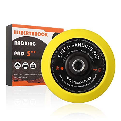
👍 TURN YOUR GRINDER INTO SANDER – 5'' polishing pad fits standard grinders with 5/8-11 threads. Easy to install, holds hook and loop paper perfectly.Better than a random orbit sander, design for your grinder.

Components: the set includes a plastic back pad and a 5/8 in.-11 clamping nut. The nut ensures secure mounting of the pad on sanding disc for uninterrupted sanding operations
Choose the lowest-risk adapter design
Before drawing or cutting metal, place the project in one of these categories:
- Approved rotating interface: A manufacturer-approved flange, nut, backing pad, hub, collet, or adapter listed for the grinder and accessory. This is the preferred approach.
- Non-rotating custom fixture: A guide, stand, body clamp, depth stop, shroud bracket, or jig that leaves the spindle, flanges, wheel, guard, side handle, and switch unchanged.
- Custom rotating interface: A homemade hub, threaded coupler, welded arbor, extended spindle, or plate that spins with the accessory. This category should normally be replaced by a listed commercial adapter or evaluated by a qualified machinist or engineer.
If the project falls into the third category, do not treat the instructions below as proof that the design is safe. Measuring, hand-spinning, and checking runout cannot verify material strength, fatigue life, thread integrity, weld quality, or fragment containment.
Before you build: compatibility checklist
Most adapter problems begin with a mismatched standard, incomplete seating, altered flange support, or a part that flexes under load. Confirm every item before fabrication.
Disconnect and identify the grinder
- Unplug a corded grinder or remove the battery before touching the spindle, guard, flange, or adapter.
- Confirm that the switch is in the off position before reconnecting power.
- Record the grinder’s exact model number, wheel capacity, no-load speed, spindle thread, and approved accessory types.
- Read the grinder manual and the accessory instructions. Do not assume that instructions for a similar-looking model apply.
- Inspect the tool for a damaged cord, plug, battery mount, switch, side handle, spindle lock, guard clamp, or gear housing.
OSHA’s Hand and Power Tools guidance advises disconnecting tools before servicing, cleaning, or changing accessories and keeping safety guards installed.
Spindle interface: threads, shaft size, and locking method
Your grinder may use a threaded spindle, inner flange, outer nut, shoulder, locating boss, or another model-specific arrangement. Confirm:
- Thread size and pitch, including whether the thread is metric or imperial.
- Thread direction and rotation, because the assembly must resist loosening during normal operation and coast-down.
- Spindle shoulder and locating face, not just the thread diameter.
- Full, undamaged engagement without bottoming out before the accessory is properly clamped.
- The approved locking method, such as the supplied flange nut, threaded hub, keyed connection, or manufacturer-designed clamp.
- Wheel spacing and guard clearance after every component is installed.
Do not use washers, pipe fittings, plumbing couplers, stacks of spacers, jam nuts, or partially engaged threads to solve a mismatch.
Accessory type and required RPM rating
Cutting wheels, grinding wheels, flap discs, diamond wheels, wire brushes, sanding pads, and polishing accessories have different mounting and loading requirements. The accessory’s marked maximum speed must meet or exceed the grinder’s maximum speed.
For portable abrasive-wheel tools, OSHA 1910.243(c)(5) requires the machine speed to be checked so it does not exceed the maximum operating speed marked on the wheel. It also requires the wheel to fit freely on the spindle and the contact surfaces to remain flat and free of foreign material.
Do not estimate the speed rating from wheel size, brand, color, thickness, or material. Read the wheel marking and current manufacturer documentation. If the maximum speed is missing, unreadable, or lower than the grinder speed, do not use the accessory.
Inspect the wheel or accessory before mounting
- Look for cracks, chips, dents, distortion, damaged threads, missing wires, loose segments, water damage, or contamination.
- Check any expiration, use-by, batch, or storage instructions supplied by the manufacturer.
- Perform a ring test only when it is appropriate for that wheel type and required by the applicable instructions. Some wheels and accessories cannot be meaningfully ring-tested.
- Never mount a wheel that has been dropped unless the manufacturer’s inspection procedure confirms it remains usable.
- Do not use an accessory that has already been altered, drilled, welded, ground, or forced onto another spindle.
Guard, flange, and side-load compatibility
A usable adapter must leave room for the guard specified for the exact accessory and must preserve the accessory’s intended support. Check that:
- The correct grinding, cutting, wire-wheel, or shroud system is installed as required by the grinder and accessory instructions.
- The guard can be positioned between you and the exposed wheel path.
- The guard clamp locks securely and does not contact the rotating assembly.
- The original inner and outer flange surfaces sit flat, clean, and in the specified orientation.
- The accessory is not pinched, bent, distorted, or clamped against an uneven surface.
- A wheel-hole bushing does not extend beyond the wheel or contact the flanges.
- The adapter does not apply side pressure to a thin cut-off wheel.
Thin cut-off wheels are intended for cutting on the edge, not grinding on the face. Use side pressure only when the accessory manufacturer specifically permits it.
Alignment and stiffness
A well-made fixture keeps the accessory axis or cutting path straight. Check for:
- Minimal runout, meaning the wheel, pad, or hub does not move side to side or up and down as it turns.
- Rigid support that does not chatter, twist, or deflect under expected force.
- Flat contact surfaces with no burrs, weld spatter, paint, rust scale, thread damage, or trapped debris.
- A positive locating feature rather than relying only on loosely fitted bolt holes.
- Enough clearance for the wheel, guard, workpiece, side handle, hands, cord, and battery.
Do not invent a universal runout tolerance. Follow the grinder, accessory, bearing, hub, or fixture manufacturer’s limit. Visible wobble is an automatic rejection.
How you will connect components mechanically
Adapters may use welded brackets, bolted plates, machined sleeves, threaded parts, or clamp-on mounts. Select the method that creates a stable and inspectable connection without modifying the grinder’s safety-critical parts.
- Bolted adapters are easier to inspect and service, but they need correctly sized, grade-marked fasteners, proper engagement, suitable torque, and a locking method compatible with heat and vibration.
- Welded brackets can be strong, but welding can distort holes, locating faces, clamps, and nearby threads.
- Clamped fixtures must grip a suitable part of the grinder housing without crushing it or depending on friction alone where a slip would expose the wheel.
- Machined rotating parts require appropriate material, concentric machining, verified thread form, balanced geometry, and professional inspection.
Pro Tip: Mark the orientation of the hub, adapter, flange, and accessory during mock-up. If the high point of a measured wobble moves when one part is rotated, that helps identify which contact surface or component is causing the error. It does not, by itself, certify the assembly for use.
Parts and materials to consider
Exact parts depend on the approved accessory or the non-rotating fixture you want to mount. Common components include:
- Compatible center hub or locating feature that matches the intended mounting system without forcing the grinder spindle.
- Outer plate or bracket that connects to a guide, shroud, stand, or fixture.
- Reinforcement ribs or formed sections that reduce bending without interfering with the grinder.
- Grade-marked fasteners and a locking method suitable for the expected vibration and temperature.
- Bearings, bushings, or spacers only when specified for the design and prevented from contacting the wheel flanges incorrectly.
- Protective covers, shrouds, screens, or guards required for the accessory and material.
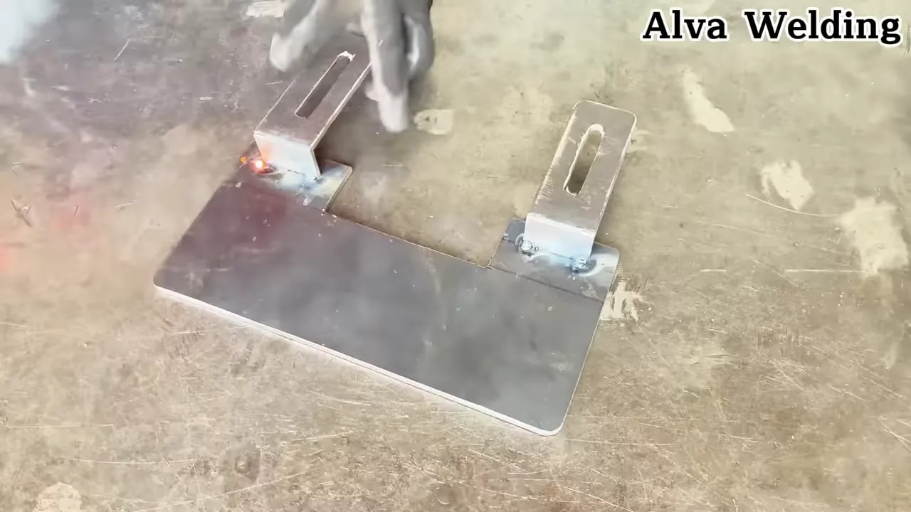
If the project involves welding, control heat and distortion. Tack the parts, allow them to cool, and re-check squareness and alignment before completing the welds. After welding, inspect for cracks, undercut, incomplete fusion, spatter on seating surfaces, and heat damage. Do not weld a precision spindle nut, wheel flange, abrasive wheel, or unknown plated component.
Products Worth Considering

【Compatibility Notice】Ensure your angle grinder's spindle/bore diameter matches the stand's clamping range of 1.65 inches (42 mm). Always measure your tool’s specifications before purchasing to confirm fitment

High Quality: The Angle Grinder Stand is made of premium plastic material, durable to use. And the spring tough spring returns quickly and does not deform after being stretched. Its non-slip silicone fixed shaft can provide more accurate positioning.

DURABLE CONSTRUCTION: This electric drill angle grinder attachment is made of solid steel and alloy materials, providing stability and strength when used at high speeds, ensuring long-term performance and wear resistance when cutting, sanding or grinding
Do not build or use these adapter setups
Some adapter concepts should be rejected before fabrication. Do not proceed with a setup that:
- Requires removing, defeating, cutting, or permanently fixing the required guard.
- Uses a wheel or accessory with a lower RPM rating than the grinder’s maximum speed.
- Mounts an oversized wheel that exceeds the grinder’s stated wheel capacity.
- Uses an unapproved wood-cutting saw blade, chain-style carving wheel, or unknown toothed accessory on a standard angle grinder.
- Replaces the factory flange system with washers, scrap plate, pipe fittings, or an improvised nut.
- Relies on only a few damaged threads, thin sheet metal, soft spacers, or unknown scrap material.
- Creates visible wobble, vibration, slipping, rubbing, overheating, or wheel movement.
- Blocks the side handle, switch, vents, battery release, cord path, or safe grip area.
- Changes a cut-off wheel into a side-grinding accessory.
- Requires anyone to stand in the wheel’s plane during start-up.
- Cannot be fully inspected after assembly.
Warning: If an adapter solves a fit problem by removing the guard, forcing a wheel onto the spindle, reducing flange contact, exceeding the wheel rating, or changing the accessory’s intended use, it is not a usable adapter. Stop and select the correct accessory or tool.
Step-by-step: build a stable grinder adapter
The steps below are best suited to a non-rotating guide, shroud bracket, stand, or fixture. Do not interpret them as engineering approval for a homemade hub that carries a wheel at grinder speed.
- Choose a safe project scope
- Decide whether the custom part will remain stationary or rotate with the accessory.
- Use an approved commercial component for the rotating spindle interface whenever possible.
- Stop if the design requires modifying the spindle, flanges, wheel, guard, switch, or gear housing.
- Disconnect and identify the tool
- Unplug the grinder or remove its battery.
- Confirm the switch is off.
- Record the model, spindle specification, wheel capacity, maximum speed, and approved accessory types from the manual and nameplate.
- Measure and verify compatibility
- Confirm the spindle thread, pitch, direction, shoulder, and flange arrangement.
- Measure the accessory arbor, hub, contact area, overall thickness, and guard clearance.
- Check the accessory instructions for size, RPM, load direction, flange, backing pad, and guard requirements.
- Inspect the tool and accessory
- Check the grinder, guard, flange, nut, spindle threads, and side handle for damage.
- Inspect the accessory for cracks, chips, distortion, wear, damaged threads, or missing markings.
- Ring-test an abrasive wheel only when that test is appropriate for the wheel type and instructions.
- Create a powerless mock-up
- Dry-fit all parts without power connected.
- Confirm that the accessory or guide sits square and does not bind.
- Hand-rotate the assembly through a full revolution where safe to do so.
- Confirm that the guard, side handle, switch, vents, cord, and battery remain fully usable.
- Prepare the hub, plate, or mount
- Deburr all edges and holes.
- Remove paint, rust, weld spatter, and dirt from seating faces.
- Add locating features and alignment marks so the parts cannot shift unnoticed.
- Keep weld heat and cutting damage away from threads and precision faces.
- Assemble using the selected method
- If welding a non-rotating bracket, tack first and re-check alignment before finishing the welds in a balanced sequence.
- If bolting, use the specified fastener grade, engagement, torque, and locking method.
- If a bushing or spacer is permitted, confirm that it cannot touch the flanges or distort the accessory.
- Do not use adhesive, threadlocker, or a lock washer as a substitute for correct mechanical design.
- Check runout, clearance, and retention
- Spin the disconnected assembly by hand and look for wobble, rubbing, or shifting.
- Use a dial indicator when evaluating a rotating hub or locating surface.
- Confirm that all marks remain aligned and the fasteners retain their position.
- Reject the setup if any part walks, rubs, binds, flexes, or changes position.
- Prepare a controlled test area
- Remove bystanders from the fragment and spark path.
- Clear rags, solvents, fuel, sawdust, grain dust, and other combustible material.
- Clamp the workpiece and confirm stable footing.
- Install the side handle and position the guard between you and the wheel.
- Perform a guarded no-load test
- Wear safety glasses with side protection, a face shield where appropriate, hearing protection, snug gloves, suitable clothing, and task-specific respiratory protection.
- Reconnect power only after confirming the switch is off.
- Hold the grinder with both hands and stand outside the wheel plane.
- Run it briefly without load and stop immediately if you see wobble or feel abnormal vibration.
- Verify under light load
- Begin with a light, controlled pass and do not force the accessory.
- Listen for chatter, scraping, clicking, pulsing, or unusual speed changes.
- Stop, disconnect power, and re-check fasteners, seating, alignment marks, guard clearance, and heat before continuing.
Safety checklist for DIY angle grinder adapters
Grinding and cutting involve high-speed rotating parts, sparks, dust, noise, electrical hazards, kickback, and flying fragments. Use this checklist every time:
- Disconnect before adjustment. Unplug the grinder or remove the battery before mounting, cleaning, measuring, or changing any component.
- Use eye and face protection. Wear safety glasses with side protection. Add a face shield for fragment and spark exposure; a face shield does not replace safety glasses. OSHA 1910.133 addresses workplace eye and face hazards from flying particles.
- Control noise. Use suitable hearing protection and limit exposure. In covered workplaces, OSHA 1910.95 sets an 85 dBA eight-hour time-weighted average as the hearing-conservation action level.
- Check the maximum speed. The accessory rating must meet or exceed the grinder’s maximum speed.
- Use the correct guard. Keep the accessory-specific guard installed, locked, and positioned between you and the wheel.
- Use two hands. Install the side handle unless the manufacturer supplies a different approved operating method.
- Inspect before mounting. Reject cracked, chipped, distorted, wet, contaminated, expired, unmarked, or damaged accessories.
- Avoid unintended side loading. Do not grind with the face of a thin cut-off wheel.
- Secure the work. Clamp the workpiece so it cannot grab, roll, close on the wheel, or pull the grinder out of line.
- Control sparks and fire. Remove flammable liquids, rags, dust piles, fuel, paper, and wood debris from the spark path. Follow applicable hot-work rules in a workplace.
- Identify the material. Determine whether grinding can release silica, lead, chromium, paint dust, plating, toxic coatings, or combustible dust.
- Use suitable dust controls. For applicable masonry and concrete work, use the shroud, water delivery, extraction, ventilation, and respiratory protection required for the task. OSHA 1926.1153 lists specific controls for handheld grinders used on silica-containing materials in construction.
- Keep clothing controlled. Wear snug, non-melting work clothing and keep hair, cords, jewelry, drawstrings, and loose fabric away from the rotating accessory.
- Control the test area. Keep other people out of the wheel plane, fragment path, dust cloud, and spark path.
If you notice vibration, wobble, burning, slipping, unusual heat, a changing sound, or the accessory walking on the mount, release the switch, wait for a complete stop, disconnect power, and remove the setup from service.
Common mistakes that cause wobble or failure
These issues are common in custom grinder setups:
- Wrong spindle thread or interface, causing partial or damaged engagement.
- Threading onto the spindle without locating on the proper shoulder, leaving the part off-center.
- Accessory not seated fully, causing imbalance and uneven flange pressure.
- Reversed, missing, damaged, or incompatible flanges.
- Overheating during welding, which distorts a hub, plate, clamp, or seating surface.
- Thin adapter plates that flex under load.
- No centering strategy, such as relying only on oversized bolt holes.
- Improper fasteners, insufficient engagement, incorrect torque, or no suitable locking method.
- Dirty contact surfaces that prevent the flanges or adapter faces from sitting flat.
- Using a bushing as a structural repair instead of correcting the adapter geometry.
- Changing the wheel position so the guard no longer provides the intended coverage.
- Testing under load too soon before inspection, hand rotation, runout checks, and a no-load test are complete.
- Assuming one successful run proves the design, even though heat, fatigue, impact, and repeated starts can loosen or crack parts later.
How to validate performance before real work
Validate the adapter in stages and stop at the first failed check.
- Manual checks
- Disconnect power and confirm full seating.
- Look for gaps, incomplete thread engagement, tilted flanges, or uneven contact.
- Check that the guard clears the accessory through a full rotation.
- Confirm that the spindle lock, side handle, switch, vents, battery, and cord work normally.
- Verify that no fastener or bracket can enter the wheel path if it loosens.
- Measured alignment check
- Use a fixed reference or dial indicator to find radial and side movement.
- Rotate individual parts during the powerless mock-up to identify the source of any high point.
- Use the applicable manufacturer’s runout limit rather than inventing a general tolerance.
- No-load inspection
- Clear the area and stand outside the wheel plane.
- Bring the grinder to operating speed while holding it with both hands.
- Stop if the adapter wobbles, rubs, clicks, shifts, or produces abnormal vibration.
- Disconnect power and re-check fasteners, marks, contact surfaces, and guard clearance.
- Controlled test cuts or passes
- Use minimum practical force.
- Keep both hands on the grinder and maintain stable footing.
- Do not twist a cut-off wheel or force it through a pinched cut.
- Watch the accessory wear pattern and check whether the fixture flexes or moves.
- Post-test inspection
- Disconnect power and allow hot parts to cool.
- Look for loosened hardware, heat marks, shiny rub points, cracks, damaged threads, shifted alignment marks, or permanent deformation.
- Discard or rebuild the adapter if anything moved, loosened, cracked, rubbed, or deformed.
A grinder adapter is not proven safe because it survived one spin. It must remain centered, guarded, fully retained, and predictable through repeated starts, light load, heat, vibration, inspection, and coast-down.
Maintenance and re-check schedule
Welded, bolted, clamped, and machined assemblies can loosen, wear, corrode, or crack. Follow the grinder and accessory instructions first, then use these condition-based checks:
- Before every use: inspect the guard, wheel, threads, flanges, fasteners, welds, alignment marks, cord or battery interface, and visible clearances.
- After the first test and after each session: look for loosened hardware, heat discoloration, rub marks, cracks, wear, and movement at locating points.
- At intervals based on use: re-check flatness, runout, fastener condition, clamp pressure, and wear. Heavy, frequent, dusty, wet, or vibrating service requires more frequent inspection.
- Any time vibration or sound changes: stop immediately and inspect the wheel, spindle, flanges, bearings, adapter, and workpiece setup.
- After a drop, jam, kickback, wheel breakage, or impact: remove the grinder and adapter from service until every affected component has been inspected.
- After welding or repair: repeat the complete alignment, clearance, runout, no-load, and light-load validation process.
Do not repeatedly tighten a loosening fastener and return to work. Recurring movement means the design, locking method, fit, or load path is wrong.
Frequently Asked Questions
What is the safest way to make an angle grinder adapter?
The safest approach is to use a manufacturer-approved adapter for every part that rotates with the accessory. Limit DIY fabrication to a non-rotating guide, stand, shroud bracket, or fixture that leaves the spindle, factory flanges, wheel, guard, side handle, vents, and switch unchanged.
Can I make a homemade hub that carries a grinding wheel?
A homemade rotating hub is the highest-risk adapter type. Thread fit alone does not verify material strength, flange support, balance, fatigue resistance, or retention at grinder speed. Use an approved commercial hub or have the complete design evaluated and produced by a qualified professional for the exact grinder and wheel.
Can I weld an adapter directly to a grinder attachment hub?
Do not weld a factory flange, spindle nut, threaded wheel hub, or other precision rotating component unless the manufacturer expressly permits it. Welding can change the material and distort the locating surfaces. Welding is more appropriate for a non-rotating fixture, followed by cooling, inspection, and a complete alignment check.
How do I choose an accessory for an adapter?
Match the accessory to the task, then verify its maximum speed, diameter, arbor or thread, flange or backing-pad requirement, guard type, rotation, and permitted load direction. The grinder manual must also list that accessory category as suitable. Do not use an unmarked accessory or one with missing instructions.
Should every abrasive wheel be ring-tested?
No. Ring testing is appropriate for certain vitrified abrasive wheels, but it is not suitable for every wheel, disc, brush, diamond product, or mounted accessory. Inspect every accessory and follow its manufacturer’s specific test and mounting instructions. Never use a ring test as the only inspection.
Why does my grinder adapter wobble?
Common causes include the wrong spindle interface, incomplete seating, damaged threads, reversed flanges, burrs, trapped debris, welding distortion, uneven faces, loose fasteners, weak material, or a damaged accessory. Disconnect the grinder and remove the adapter from service. Visible wobble is a rejection sign, not a normal adjustment.
Is it okay to use an adapter for side grinding?
Only apply side pressure when the accessory is designed, guarded, and rated for face grinding. Thin cut-off wheels are intended to cut on their edge. If the adapter bends the wheel, applies side load, or changes the accessory’s intended cutting direction, use a different wheel or tool.
Can I use a larger wheel if I make an adapter?
No. Do not use an adapter to fit a wheel larger than the grinder’s stated capacity. A larger wheel may exceed the guard opening, increase surface speed and leverage, overload the spindle and bearings, and place more of the wheel in the fragment path.
When should I replace or discard a DIY grinder adapter?
Discard or rebuild it after cracks, bending, damaged threads, loosened fasteners, worn locating faces, heat damage, corrosion, increased vibration, visible wobble, shifted alignment marks, a drop, a jam, or any sign that the accessory or fixture moved during use.
Key takeaway
A DIY angle grinder adapter can expand workshop capability only when the project stays within a defensible safety boundary. Prefer approved rotating components, keep the correct guard and factory flange system, disconnect power before every adjustment, match the accessory speed and intended load, control dust and sparks, and test in short stages. Remove the adapter from service at the first sign of movement, damage, heat, rubbing, wobble, or abnormal vibration.
Sources
- OSHA 1910.243 — Guarding of Portable Powered Tools — supports portable grinder guarding, wheel inspection, maximum-speed checks, spindle fit, flat contact surfaces, and bushing requirements.
- OSHA — Hand and Power Tools — supports disconnecting tools before accessory changes, preserving guards, inspecting abrasive wheels, securing work, and staying outside the wheel plane during start-up.
- OSHA 1910.133 — Eye and Face Protection — supports protection from flying-particle hazards.
- OSHA 1910.95 — Occupational Noise Exposure — supports workplace noise monitoring, hearing-conservation, and hearing-protector guidance.
- OSHA 1926.1153 — Respirable Crystalline Silica — supports dust shrouds, extraction, water delivery, ventilation, and respiratory controls for applicable grinder tasks involving silica-containing material.
- DEWALT Abrasive Safety Guides — provides manufacturer guidance organized by bonded abrasives, flap discs, diamond products, resin-bonded wheels, and wire brushes.