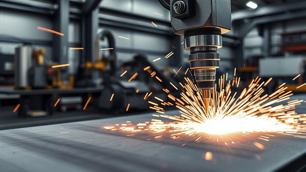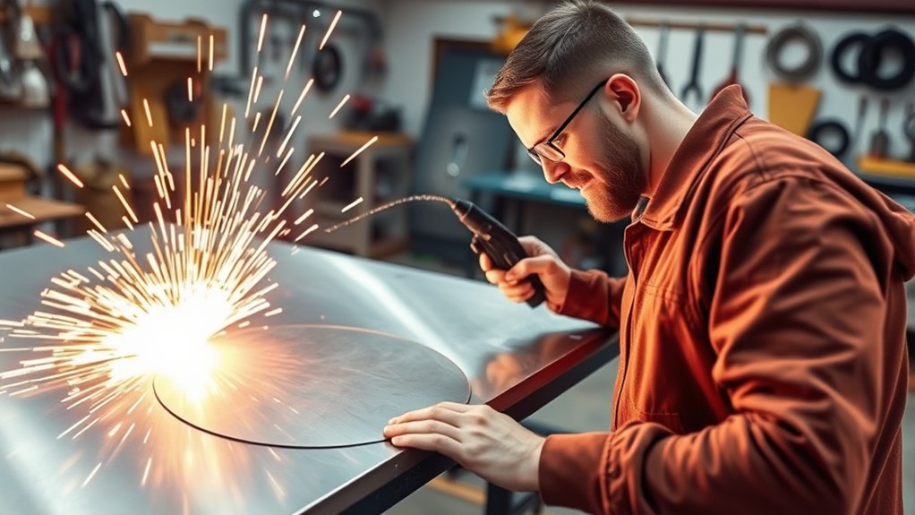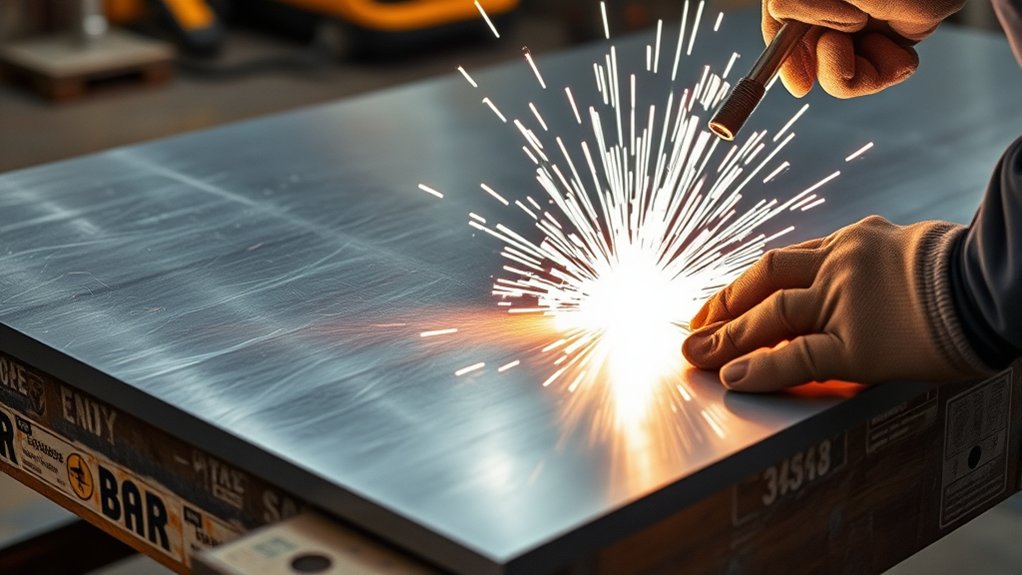
Making a straight plasma cut is less about holding your hand perfectly still and more about controlling the entire setup. A rigid guide, a measured torch offset, clean and correctly regulated air, suitable consumables, and steady travel speed all affect the result. You also need to distinguish a straight cut line from a perfectly square edge, because some kerf bevel is normal with conventional plasma cutting.
Quick Answer
To cut a straight line with a plasma cutter, clamp a noncombustible straightedge beside the marked line, measure the required guide offset with a scrap cut, and use the consumable, amperage, airflow, and standoff listed for your machine. Keep the torch perpendicular and move steadily while watching the sparks below the plate.
Key Takeaways
- Use the operator manual and cut chart for your exact plasma cutter, torch, consumable, material, and thickness.
- Measure the distance between the guide-contact point and the kerf before positioning the straightedge.
- Use a drag shield only when the torch and consumable are designed for direct contact; otherwise maintain the listed standoff.
- Keep the torch close to 90 degrees and adjust travel speed by observing the sparks and finished cut edge.
- Control fumes, fire, ultraviolet radiation, noise, hot slag, and electrical hazards before starting the cut.
At a Glance
| Time Required | About 20–45 minutes for setup, marking, and a test cut; the final cut time depends on length and material thickness. |
| Difficulty | Beginner to intermediate |
| Tools Needed | Plasma cutter, correct consumables, adequate air supply, work clamp, steel straightedge, clamps, tape measure, marker or scribe, scrap metal, and complete PPE |
| Cost | No added cost if you already own a suitable guide and PPE; filters, replacement consumables, or a purpose-made guide add a model-dependent cost. |
Warning: Plasma cutting creates ultraviolet radiation, hot sparks, molten slag, fumes, noise, and electrical hazards. Wear suitable eye and face protection, safety glasses with side shields, flame-resistant clothing, welding gloves, hearing protection, and closed leather footwear. Remove combustible material, keep an appropriate extinguisher nearby, and use adequate ventilation or local exhaust. Do not cut a closed container or a container that held fuel, solvent, or another hazardous substance unless it has been professionally cleaned and declared safe.
Preparing Your Work Area for Plasma Cutting

Start with a stable cutting table or other noncombustible support that allows sparks and molten metal to fall without striking hoses, cords, stored material, or your feet. Do not cut over a solid bench that traps molten metal against the underside of the workpiece.
Move paper, cardboard, sawdust, fuel, aerosols, solvents, oily rags, and other flammable material away from the cutting area. OSHA requires movable fire hazards to be removed or protected and suitable extinguishing equipment to be immediately available during cutting work. Review the OSHA fire-prevention requirements for welding and cutting.
Clamp the metal securely so it cannot vibrate, lift, or shift as the torch presses against a guide. Support both the keep piece and the drop piece without trapping the cut or allowing the falling section to pull on the torch lead.
Provide enough ventilation to keep fumes out of your breathing zone. Plasma cutting melts metal and can generate airborne metal fumes. Coatings, paint, oil, galvanizing, stainless steel, copper alloys, and other materials can add hazardous contaminants. OSHA’s welding, cutting, and brazing hazard guidance identifies fumes, ultraviolet radiation, burns, eye injury, electrical shock, and other hazards that require engineering controls, safe practices, and PPE.
- Identify the material: Confirm the metal is electrically conductive and determine whether it is coated, plated, painted, oily, or contaminated.
- Control the fumes: Position local exhaust close enough to capture fumes without pulling the plasma stream sideways.
- Protect both sides: Check below and behind the work because sparks and heat can pass through openings or ignite material out of sight.
- Mark hot metal: Use pliers or appropriate gloves and clearly separate hot cutoffs from cool stock.
- Protect bystanders: Use screens and keep other people away from the arc, spark path, and falling material.
Choose an eye-protection shade suitable for the process and current. OSHA lists shade 8 as the minimum for light plasma arc cutting below 300 amps when the arc is visible, but the machine manual or a darker comfortable shade may call for greater protection. See the OSHA eye and face protection standard.
Setting Up the Plasma Cutter Equipment

Place the plasma power supply where air can circulate around its vents and where sparks cannot enter the case. Keep the torch lead, air hose, and power cord away from the cut path and hot drop pieces.
Before connecting or inspecting equipment, set the power switch to off and follow the electrical-isolation instructions in the operator manual. Confirm that the supply circuit, plug, extension cable, generator, and line-disconnect arrangement meet the cutter’s voltage, phase, amperage, and grounding requirements. Do not improvise adapters or undersized extension cords.
Some cutters use an external compressor, while others have a built-in compressor or use bottled process gas. Do not assume that every machine has the same regulator, air lever, torch-lock switch, mode control, or starting system.
Proper Cable Connections
Install the torch and consumables exactly as shown in the manual. Connect the torch lead and work lead firmly, then attach the work clamp to clean, conductive metal. Place it on the portion that will remain supported—not on the section that will fall away after the cut.
Note: The return cable is commonly called a ground lead, but its clamp is the plasma cutting work clamp. It completes the cutting circuit and is not a substitute for the equipment’s protective electrical grounding conductor.
| Check | Correct Action | Why It Matters |
|---|---|---|
| Power | Use the voltage, phase, circuit capacity, and connection method listed for the machine. | Prevents nuisance trips, voltage drop, overheating, and unsafe wiring. |
| Torch and work lead | Seat and lock every connector; inspect leads for cuts, burns, loose fittings, or crushed areas. | Loose or damaged connections can cause unstable starting and poor cut quality. |
| Work clamp | Clamp to clean metal on the supported side, as close to the cut as practical. | Provides a reliable current path and avoids losing the connection when the cutoff drops. |
| Consumables | Install the correct shield, nozzle, electrode, swirl ring, retaining cap, or cartridge for the intended mode. | Incorrect or damaged parts can cause bevel, dross, double arcing, failed starts, and short life. |
Securing the Air Supply
Connect the cutter to the process gas specified by its manufacturer. For an air-plasma system, the supply normally needs to be clean, dry, and oil-free. Moisture, oil mist, rust, and compressor debris can destabilize the arc and shorten consumable life.
Do not judge compressor compatibility by tank size or maximum pressure alone. Check all of the following:
- Required inlet pressure: Use the value in the exact operator manual.
- Required airflow: Confirm the compressor can supply the listed SCFM or CFM at the required pressure.
- Duty cycle: Make sure the compressor can maintain that flow throughout the planned cut without continuously falling behind.
- Pressure while flowing: Use the machine’s gas-test or purge function when the manual calls for it; static pressure may appear adequate and then collapse during a cut.
- Air treatment: Drain the compressor tank and maintain filters, separators, dryers, and regulators.
Hypertherm’s plasma gas-selection guidance explains that shop air must be cleaned to remove particles, oil mist, and moisture. In humid or high-use conditions, additional filtration or a refrigerated or desiccant dryer may be needed.
Pro Tip: If the pressure gauge looks normal but the arc becomes weak during a long cut, test pressure and airflow while the gas is flowing. A restrictive coupler, small hose, clogged filter, waterlogged separator, or undersized compressor can create a pressure drop that is invisible at rest.
Adjusting the Plasma Cutter Settings

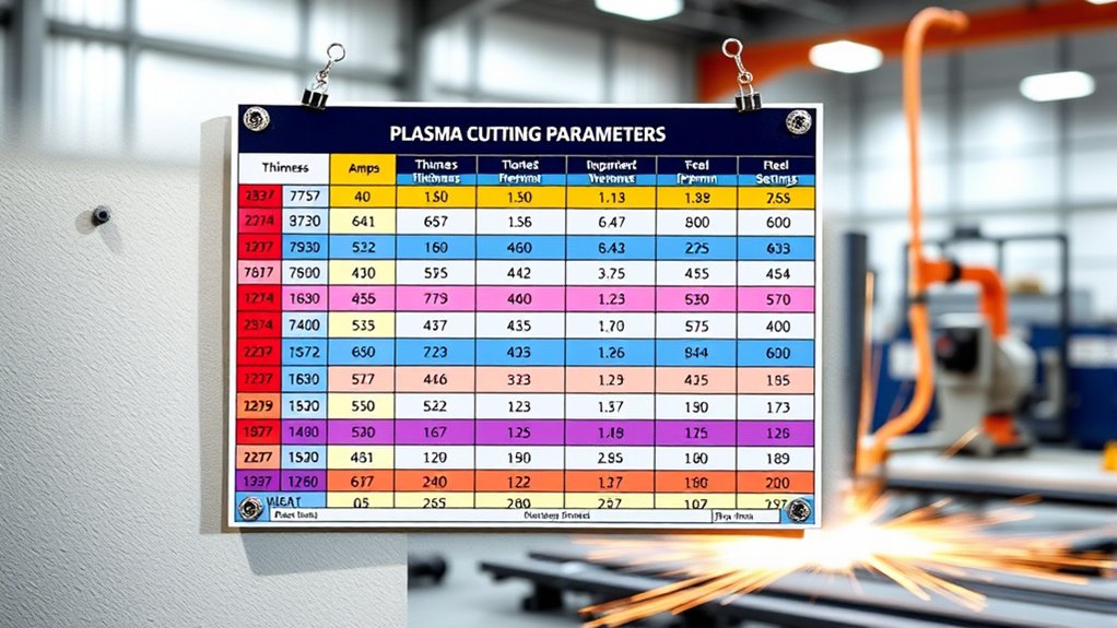
Select the settings from the cut chart for your exact machine, torch, consumable, metal type, and thickness. A generic amperage or pressure chart can be misleading because two cutters with the same maximum output may use different consumables, airflow, standoff, travel speed, and rated capacity.
Use the manufacturer’s documents library or the equivalent support page for your brand to find the latest operator manual and cut chart. Do not rely on the machine’s maximum severance rating when you need a clean, accurate edge; use the recommended quality-cut range.
| Setting | How to Select It | Common Sign It Is Wrong |
|---|---|---|
| Mode | Choose normal cutting rather than gouging, marking, or expanded-metal mode unless the manual directs otherwise. | Unstable arc, poor penetration, or excessive heat. |
| Amperage | Match the chart and installed consumable. Lower-output processes often improve detail on thin metal. | Excessive bevel, wide kerf, heavy dross, or incomplete cutting. |
| Air pressure and flow | Set or verify them using the manual and any built-in gas-test procedure. | Weak arc, short consumable life, heavy dross, or a cut that stops penetrating. |
| Torch standoff | Drag only with a compatible drag shield or cartridge; otherwise hold the specified gap. | Nozzle damage, double arcing, excessive bevel, or wandering. |
| Travel speed | Begin with the cut-chart value or a scrap test, then read the sparks and edge. | Upward sparks, uncut sections, excessive dross, or a heat-distorted sheet. |
Inspect the nozzle or cartridge before cutting. Replace consumables that have cracks, deformed openings, heavy pitting, burns, blocked gas passages, or other damage. A nozzle opening that is no longer round can deflect the arc and make the cut wander even when the guide is straight.
Products Worth Considering

The suitable plasma torch: Plasma spring guide AG60 / SG55 WSD60 plasma cutting torch

WITH GRADUATED SCALE: This plasma cutter comes with a graduated scale. This design enables the user to use the scale to intuitively and conveniently locate the cutting diameter, cutting more convenient and quick.

[Achieve Precise Cuts] PT31 Plasma Cutting Consumables – Your Essential Tool for Efficient Cutting! Whether you're working with sheet metal, steel, or any other material, superior cutting performance ensure clean, accurate, and smooth cuts.
Understanding Straightness, Kerf, and Bevel
A straight guide controls the path of the torch, but it does not guarantee that both faces of the kerf will be perfectly square. Three different measurements matter:
- Line straightness: Whether the cut follows the intended line without wandering.
- Kerf width: The strip of material removed by the plasma arc.
- Cut-edge bevel: The difference between the width at the top and bottom of the cut.
Some bevel is inherent in conventional plasma cutting because of the shape and swirl of the plasma jet. Hypertherm’s cut-angularity guidance reports typical bevel of about 1–3 degrees on the better side of a conventional plasma cut and 3–8 degrees on the opposite side. Worn consumables, an angled torch, incorrect standoff, poor airflow, excessive amperage, and the wrong travel speed can make it worse.
A straight cutting guide controls where the kerf goes; correct consumables, torch position, airflow, amperage, speed, and cut direction control how square and clean the edge becomes.
Choosing and Using the Right Guide for Straight Cuts

A rigid steel guide is usually the safest and most durable choice for straight handheld cuts. Angle iron, square tubing, flat bar, a framing square, or a purpose-made torch track can all work if the torch body or drag shield can move along the edge without catching.
The guide must be straight, firmly clamped, and tall enough to control the torch without interfering with the nozzle, shield, trigger, or airflow. Check that the clamps remain outside the torch path.
Products Worth Considering

Holds straight edge or Plasma Stencil where a clamp won't reach


fit SG-55 AG-60 WSD-60 Plasma Cutter Torch
Selecting Effective Guide Materials
- Steel angle, flat bar, or square tubing: Durable, noncombustible, easy to clamp, and suitable for repeated shop use.
- Purpose-made torch guide or track: Helpful for repeatable work and compatible torch geometry.
- Ceramic guide: Potentially heat resistant but brittle; use only when it is stable, undamaged, and positioned so sparks cannot strike an unsafe surface.
- Wood or MDF template: Easy to shape but combustible. Keep it outside the spark and slag path, do not treat it as fireproof, and stop if it scorches or smolders.
- Solid-surface material such as Corian: Can be used by some fabricators as a template, but it can scorch and may release irritating fumes. A noncombustible metal guide is the better default.
- Plastic: Avoid ordinary plastic near the arc because it may melt, burn, deform, or release fumes.
The guide’s conductivity does not determine consumable life. Direct contact depends on the torch’s shield and consumable design. Hypertherm’s drag-tip guidance explains that a compatible drag shield electrically isolates the nozzle so the torch can contact the workpiece or follow a straightedge without double arcing.
Measuring the Guide Offset
The marked cut line cannot normally sit directly under the guide because the arc exits near the center of the torch while the torch body or shield rides against the guide. Measure this offset instead of guessing.
- Mark the keep side. Draw the desired finished edge and clearly mark which side of the line must remain.
- Use matching scrap. Select scrap of the same material and thickness and install the same consumable you will use for the final cut.
- Clamp the guide. Position a straightedge near a test line and run the torch against it using the intended drag or standoff method.
- Measure the result. After the metal cools, measure from the guide-contact edge to the finished edge of the kerf on the keep side.
- Transfer the offset. Place the production guide that measured distance away from the desired finished edge.
- Verify both ends. Measure from the marked line to the guide near the beginning and end before tightening the clamps.
- Make a short test cut. Confirm the final edge lands where expected before committing to a long or valuable piece.
Pro Tip: Keep a labeled offset sample for each torch, drag shield, cartridge, and straightedge combination. Changing the consumable stack or the side of the torch that touches the guide can change the offset.
Executing the Plasma Cut With Precision

Review the torch-lock, trigger, starting, piercing, and shutdown instructions for your model before firing the arc. The following sequence applies to a typical handheld straight cut, but your machine’s manual takes priority.
- Choose an edge start when possible. Position the torch at the plate edge. Edge starting normally reduces molten blowback and can extend consumable life compared with piercing.
- Confirm the drop zone. Make sure the cutoff can fall safely without striking your body, hose, work clamp, power cable, or compressor line.
- Position the torch. Hold it close to 90 degrees to the top surface. Let the compatible drag shield or guide attachment contact the straightedge without forcing the torch sideways.
- Start the arc correctly. Use the torch trigger and starting procedure described in the manual. Pause at the edge until the arc has passed completely through the plate.
- Pull steadily along the guide. When practical, pulling the torch toward you gives a more stable view and hand position than reaching and pushing away.
- Watch the sparks below the plate. They should exit through the bottom and trail slightly behind the torch. Sparks spraying upward usually mean the torch is moving too fast, the amperage is too low, airflow is inadequate, or the machine is beyond its clean-cut capacity.
- Keep pressure light. Do not shove the torch against the straightedge. Excessive side force can tilt the torch and create uneven bevel.
- Finish the edge. Continue until the arc fully clears the far edge. Some manufacturers recommend a slight handle lift near the end of thick cuts; use that technique only when specified for your torch.
- Release the trigger safely. Keep the torch aimed away from yourself and allow the system’s postflow to continue.
Reading Sparks and Travel Speed
Travel speed is one of the easiest settings to adjust while cutting:
- Sparks spray upward: Slow down, confirm adequate power, and check air pressure and flow.
- Sparks fall nearly straight down with heavy bottom buildup: The torch may be moving too slowly and adding unnecessary heat.
- Sparks trail behind beneath the plate: Travel speed is generally closer to the useful range.
- The cut repeatedly stops penetrating: Check thickness, amperage, consumables, input power, air supply, and whether the machine is being used beyond its quality-cut rating.
Hypertherm’s handheld guidance indicates that properly directed sparks commonly trail below the plate by roughly 15–20 degrees, although the exact appearance varies by machine, material, thickness, and process.
Using Cut Direction to Protect the Keep Side
With common clockwise-swirl consumables, the straighter or “better” edge is normally on the right side of the kerf relative to forward torch travel. Plan the direction so the valuable keep piece stays on that side. For an exterior profile, this commonly means traveling clockwise; for an interior opening, it commonly means traveling counterclockwise. Confirm the rule for your torch because consumable and gas-swirl designs can differ.
Edge Starting Versus Piercing
Use an edge start whenever the shape and workpiece allow it. If the cut must begin in the middle of the plate, stay within the machine’s rated pierce capacity and follow the manual’s pierce method.
For thicker material, many handheld systems use a rolling pierce: begin with the torch tilted so molten metal blows away from the nozzle, fire the arc at the specified height, and rotate the torch upright only after the arc penetrates. Never aim pierce spray toward yourself, a hose, a guide, or another person.
Post-Cutting Procedures and Equipment Maintenance

After the cut, release the trigger and allow the gas postflow to finish. The air cools the torch and consumable, and the machine’s internal fan may continue running as needed. Do not remove a hot cartridge or interrupt the manufacturer’s cooling sequence.
When postflow is complete, follow the machine’s normal shutdown procedure. Turn off or isolate incoming power before opening the torch, servicing the power supply, changing damaged parts, or performing other maintenance that requires de-energization.
Close the external air supply when the machine will not be used, relieve pressure only as directed, and inspect hoses and fittings for leaks. Remove the work clamp after the system is safely shut down and the metal is stable.
Remember that the workpiece and cutoff may remain hot long after visible sparks stop. Use pliers or heat-resistant gloves, place hot pieces on a noncombustible surface, and check the area for hidden fire before leaving.
Inspect and maintain the following:
- Shield or drag tip: Look for cracks, heavy spatter, erosion, or deformation.
- Nozzle: Replace it if the center opening is no longer round or shows excessive wear.
- Electrode or cartridge: Follow the manufacturer’s wear limits and replacement pairing instructions.
- Swirl ring and gas passages: Check for blockage, cracks, or incorrect assembly.
- O-rings: Inspect for damage and use only the lubricant specified by the manufacturer.
- Air filter and water separator: Drain moisture and replace clogged elements.
- Torch and work leads: Check for cuts, burns, crushed sections, loose fittings, or exposed conductors.
Coil the torch lead, work lead, and air hose in broad loops without sharp bends. Store the torch where the trigger cannot be pressed accidentally and where the consumable cannot be struck.
Troubleshooting Straight Plasma Cuts
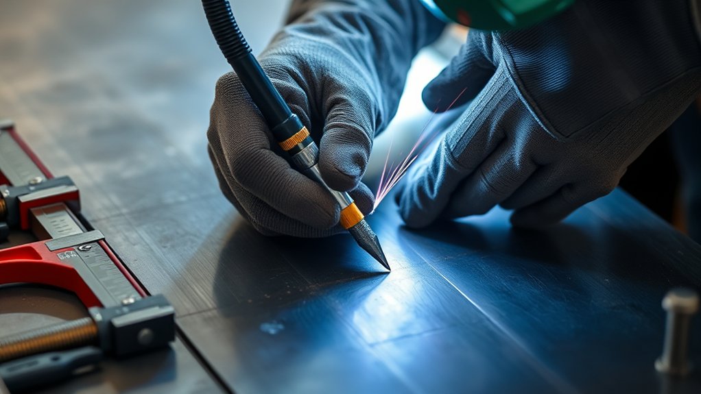
When a cut is not straight or clean, change one variable at a time and test on matching scrap. Replacing several settings at once makes it difficult to identify the cause.
| Problem | Likely Causes | What to Check |
|---|---|---|
| Cut wanders away from the line | Loose guide, uneven torch pressure, damaged nozzle, guide interference, or moving workpiece | Reclamp the work and guide, inspect the nozzle, use lighter side pressure, and verify the torch can move freely. |
| Finished edge is in the wrong location | Incorrect guide offset, wrong keep side, or changed consumable geometry | Repeat the scrap calibration and measure from the guide-contact surface to the finished kerf edge. |
| Cut does not go through | Travel too fast, inadequate amperage, low airflow, poor input power, worn consumables, or excessive thickness | Slow down, verify the cut chart, check pressure during flow, inspect consumables, and remain within the quality-cut capacity. |
| Heavy removable bottom dross | Travel too slow, excessive heat input, or unsuitable settings | Increase speed gradually and confirm the recommended amperage and consumable. |
| Hard bottom dross or sparks spraying upward | Travel too fast, amperage too low, insufficient air, or machine underpowered for the thickness | Reduce speed, verify the process settings and airflow, and use a more suitable process if necessary. |
| Excessive or uneven bevel | Torch not perpendicular, worn nozzle, incorrect standoff, wrong speed, poor airflow, or wrong travel direction | Square the torch, replace damaged parts, verify standoff and settings, and place the keep side on the better side of the kerf. |
| Thin sheet warps | Travel too slow, excessive amperage, poor support, or too much continuous heat in one area | Use the recommended lower-output process, move at the correct speed, support the sheet, and plan cuts to spread heat. |
| Torch will not ignite | Torch lock, loose consumables, safety interlock, poor work connection, low gas pressure, damaged lead, or power fault | Read the displayed fault, check the manual, reseat approved consumables with power isolated, verify gas and work-clamp connections, and seek service if the fault remains. |
Note: Do not file or grind away every symptom before diagnosing it. Dross, bevel, lag lines, discoloration, and the direction of the sparks provide useful clues about speed, torch height, airflow, consumable condition, and amperage.
Frequently Asked Questions
Can a plasma cutter be used on nonmetallic materials?
A conventional plasma arc cutter requires an electrically conductive workpiece, so it is intended for metals such as mild steel, stainless steel, aluminum, copper, brass, and other conductive alloys. It will not normally cut wood, glass, stone, or ordinary plastic. Laser, abrasive waterjet, saw, router, or other processes may suit those materials better.
How can I prevent warping while cutting thin metal sheets?
Use the manufacturer’s thin-metal consumable and recommended amperage, maintain adequate travel speed, and support the sheet so it cannot flutter. Avoid pausing in one spot. When making several cuts, sequence them so heat is distributed instead of concentrating repeatedly in one small area.
What personal protective equipment is necessary for plasma cutting?
Wear safety glasses with side shields beneath a cutting helmet or face shield with an appropriate filter shade, plus flame-resistant clothing, welding gloves, hearing protection, and closed leather footwear. Additional respiratory protection may be required when ventilation and fume controls cannot keep exposure within safe limits.
How do I know if my air compressor is compatible with the plasma cutter?
Compare the cutter’s required SCFM or CFM and inlet pressure with the compressor’s continuous output at that pressure. The compressor must maintain the required flow for the duration of the cut, not merely reach a high tank pressure. Also account for hose size, couplers, filters, moisture removal, and duty cycle.
What are the common troubleshooting steps for a plasma cutter that will not ignite?
Check the displayed fault code, input power, torch-lock position, work-clamp connection, gas pressure, airflow, and consumable installation. With power safely isolated, inspect approved consumables and leads for damage. Do not bypass a safety interlock. If the fault remains, use the service procedure for the exact model or contact a qualified technician.
Why is my plasma cut straight on top but beveled underneath?
A straight top line does not guarantee a square cut face. Some bevel is normal, but excessive bevel can come from a tilted torch, worn nozzle, incorrect standoff, wrong amperage, poor airflow, excessive or insufficient speed, or placing the keep piece on the poorer side of the kerf.
Can I run the plasma torch directly against a metal straightedge?
Yes, if the torch body, guide attachment, drag shield, or cartridge is designed for that contact. Do not drag an exposed nozzle unless the manufacturer specifically permits it. Confirm that the straightedge cannot short, obstruct, or damage the consumable and that it remains outside the molten-slag path.
Conclusion
A clean, straight plasma cut starts before the arc is fired. Prepare a fire-safe and ventilated work area, use the correct power and air supply, inspect the consumables, measure the guide offset on scrap, and clamp a rigid straightedge securely. During the cut, keep the torch perpendicular, maintain light contact with the guide, watch the sparks, and move steadily.
Do not expect the guide alone to correct worn consumables, poor airflow, wrong amperage, excessive standoff, or bad travel speed. Check the finished kerf, dross, bevel, and spark direction, adjust one variable at a time, and let postflow finish before shutting down or servicing the torch. With that repeatable process, each practice cut should become more accurate than the last.
Sources
- OSHA: Welding, Cutting, and Brazing Hazards and Solutions — fumes, ultraviolet radiation, burns, electrical hazards, and PPE.
- OSHA 1910.133: Eye and Face Protection — plasma arc cutting filter-shade guidance.
- OSHA 1926.352: Fire Prevention — combustible-material control and fire-extinguishing precautions.
- Hypertherm: How to Plasma Cut — system setup, edge starting, settings, guides, and piercing methods.
- Hypertherm Documents Library — current operator manuals, cut charts, and product-specific instructions.
- Hypertherm: Plasma Cutter Drag Tips — compatible drag shields, direct-contact cutting, templates, and speed cues.