A plasma cutting speed chart gives you a tested starting point for matching metal type, thickness, amperage, consumables, torch height, and travel speed. The key is to use the chart for your exact plasma cutter and process—not a generic amps-to-thickness rule—then confirm the settings with a short test cut before working on the finished part.
Quick Answer
Find the manufacturer cut chart for your exact machine, material, thickness, amperage, gas, and consumable. Enter the listed cut height, pierce height, pierce delay, and speed. Make a test cut, then change speed in small steps until dross, bevel, and incomplete cutting are minimized.
Key Takeaways
- There is no universal plasma cutting speed chart; settings change with the machine, torch, consumable, material, gas, and desired cut quality.
- Do not choose amperage from thickness alone. Select the manufacturer-approved process first, then use the matching speed row.
- A speed that is too fast can cause arc lag, positive bevel, incomplete cuts, and hard high-speed dross.
- A speed that is too slow can widen the kerf, increase heat input, round the top edge, and create easy-to-remove low-speed dross.
- Clean, dry air, sound consumables, stable input power, correct torch height, and steady motion are as important as the IPM setting.
At a Glance
| Time Required | 10–20 minutes to verify the chart and tune a new setup |
| Difficulty | Moderate; easier with CNC motion and automatic torch-height control |
| Tools Needed | Plasma cutter manual, correct consumables, thickness gauge or caliper, scrap metal, PPE, and a steady guide or CNC table |
| Cost | Usually no added cost beyond scrap and normal consumable wear |
Understanding the Plasma Cutting Speed Chart

A plasma cutting speed chart is a process sheet for one specific equipment combination. It normally links material thickness to amperage, consumable type, cut height, initial pierce height, pierce delay, arc voltage, travel speed, kerf width, and gas flow. Speeds are shown in inches per minute (IPM or in/min) or millimeters per minute (mm/min).
The conversion is simple: 1 IPM equals 25.4 mm/min. For example, 100 IPM equals 2,540 mm/min. Converting units does not make one machine’s chart valid for another machine, however. Two systems set to the same amperage can use different torches, nozzle designs, gas pressures, and cut speeds.
The Hypertherm Powermax45/65/85/105 SYNC Cut Charts Guide states that its values are starting points and may require adjustment for the equipment and environment. It also separates “Best Quality” settings from faster “Highest Production” settings, which can increase speed but may not produce the best edge.
Note: A chart row is valid only when you use the listed material, process, amperage, consumable, gas, and torch configuration. Treat any chart that lists only thickness, amps, and IPM as a rough illustration—not a machine setup specification.
The best cutting speed is not the highest number your machine can reach. It is the fastest stable speed that produces the edge quality, dimensional accuracy, and dross level your job requires.
Example Plasma Cutting Speed Chart
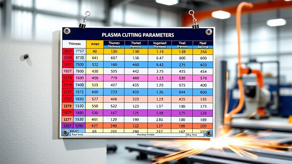
The table below is a manufacturer-specific example, not a universal chart. It summarizes selected mild-steel values from Hypertherm’s June 2024 guide for a Powermax65/85/105 SYNC using a standard 45-amp mechanized cartridge and air. The published data was collected with new cartridges and proper electrical, gas, and site conditions.
| Mild-Steel Thickness | Current | Cut Height | Initial Pierce Height | Pierce Delay | Best-Quality Speed | Highest-Production Speed | Reference Kerf |
|---|---|---|---|---|---|---|---|
| 14 gauge | 45 A | 0.125 in | 0.150 in (120%) | 0.2 sec | 278 IPM | 318 IPM | 0.065 in |
| 10 gauge | 45 A | 0.125 in | 0.150 in (120%) | 0.4 sec | 115 IPM | 162 IPM | 0.073 in |
| 3/16 inch | 45 A | 0.125 in | 0.150 in (120%) | 0.5 sec | 68 IPM | 107 IPM | 0.074 in |
| 1/4 inch | 45 A | 0.125 in | 0.150 in (120%) | 0.6 sec | 46 IPM | 74 IPM | 0.075 in |
The same guide lists very different speeds when the process changes. For 1/4-inch mild steel at 85 amps, it lists 130 IPM for best quality and 153 IPM for highest production. At 105 amps, the sample chart lists 156 and 192 IPM. This is why a statement such as “1/4-inch steel cuts at 200 IPM” is incomplete without the system, amperage, consumable, and quality target.
Factors Influencing Cutting Speed

Cut speed is one part of a connected process. Changing one setting can alter arc energy, kerf width, bevel, dross, heat input, and consumable life. The most important variables are:
- Machine and torch: Power supply design, torch type, nozzle or cartridge, and process technology set the usable range.
- Material: Mild steel, stainless steel, and aluminum may use different gases, currents, speeds, and consumables at the same thickness.
- Thickness: Thicker metal normally requires more arc energy and a slower travel speed.
- Amperage: More current can support a faster speed, but only when the consumable and process are rated for that current.
- Gas quality and pressure: Air-plasma systems need the pressure, flow, cleanliness, and dryness specified by the manufacturer. Moisture, oil, and restricted flow can damage consumables and reduce cut quality.
- Torch-to-work distance: On mechanized systems, cut height and arc voltage are linked. Excessive or inconsistent standoff can increase bevel and dross.
- Motion quality: CNC acceleration, corner slowdowns, vibration, and an unsteady handheld travel rate can prevent the torch from maintaining the chart speed.
- Consumable condition: A worn, damaged, or incorrectly assembled nozzle changes the arc and can make a correct speed look wrong.
- Power and duty cycle: Low input voltage, an undersized circuit, or exceeding the machine’s duty cycle can prevent stable output during long cuts.
How to Tell Whether the Speed Is Too Fast or Too Slow
| Condition | Common Signs | First Adjustment |
|---|---|---|
| Too fast | Arc trails behind the torch, sparks may spray back sharply, the cut may not fully penetrate, positive bevel increases, and a small hard bead of dross forms. | Reduce travel speed in small steps and recheck nozzle condition and standoff. |
| Too slow | Kerf widens, the top edge may round or spatter, heat distortion increases, and a larger bubbly deposit forms on the bottom. | Increase travel speed and confirm that current and cut height match the chart. |
| Near the target | The arc stays attached through the plate, sparks trail behind the torch in a steady pattern, bevel is controlled, and dross is minimal or easy to remove. | Record the final speed, voltage, height, pressure, and consumable set for repeat jobs. |
Pro Tip: On a CNC table, change only one variable at a time. Hypertherm’s dross troubleshooting guidance recommends reducing excessive speed in 5 IPM increments, then checking standoff and amperage if the problem remains.
Optimal Amperage Settings for Different Thicknesses

Material thickness does not map to one universal amperage. A thin sheet might be cut with a standard low-amperage process, a FineCut-style consumable, or a higher-amperage process running at a much faster mechanized speed. Each choice changes kerf, heat input, edge finish, and production rate.
Products Worth Considering

[Achieve Precise Cuts] PT31 Plasma Cutting Consumables – Your Essential Tool for Efficient Cutting! Whether you're working with sheet metal, steel, or any other material, superior cutting performance ensure clean, accurate, and smooth cuts.

PACKAGE INCLUDED: 5 Pcs Cup-15 Pcs Electrodes-10 Pcs Ring-30 Pcs Tip(Standard)

⚡【Precision Compatibility】 Exact fit for YESWELDER CUT 55DS Pro & 65DS (2019-2024 models). Replaces OEM# IPT40-55DS/65DS.
Amperage Selection Guidelines
Use this order when choosing amperage:
- Identify the exact machine and torch. Confirm the model, available output range, and whether the torch is handheld or mechanized.
- Choose the material and process. Select mild steel, stainless steel, or aluminum and the approved gas or air process.
- Install the listed consumable. Match the cartridge, nozzle, electrode, shield, and swirl ring part numbers where applicable.
- Find the exact thickness row. Do not substitute nominal gauge unless you have confirmed the actual thickness.
- Use the chart amperage and speed together. A higher current setting without enough travel speed can overheat thin metal and widen the cut.
- Test on matching scrap. Use the same alloy, thickness, surface condition, and orientation as the finished part.
Thickness-Amperage Correlation
Higher amperage usually increases cutting capacity and allows faster motion, but it may also increase kerf width and demand a different consumable. Lower-amperage or fine-cut processes can improve detail on thin material, though their usable thickness range is limited.
Also separate these three ratings:
- Recommended cut capacity: The thickness range where the manufacturer expects useful speed and cut quality.
- Maximum cut capacity: A slower cut near the system’s upper practical range, often with reduced quality.
- Severance capacity: The thickest material the arc may separate under favorable conditions; it is not a production-quality setting.
For precision work, stay inside the chart’s recommended range instead of selecting amperage solely because the machine can sever the plate.
Efficiency Through Amperage
Efficiency comes from using the correct process window, not automatically turning the machine to maximum output. If the current is too low for the chosen thickness and speed, the arc can lag and fail to penetrate. If the current is too high for a thin sheet and the operator cannot move fast enough, the kerf can widen and the plate can warp.
Never run a nozzle, tip, or cartridge above its rated current. Follow the manufacturer’s consumable chart and replace parts when the orifice becomes enlarged, oval, nicked, or contaminated.
Manual vs. Mechanized Plasma Cutting Speed
Mechanized charts assume controlled motion, repeatable torch height, and a stable path. A CNC, track burner, robot, or cobot can hold speeds that are difficult to maintain by hand. Handheld cutting also slows at curves, corners, starts, and awkward body positions.
| Setup | How to Use Speed Data | Main Limitation |
|---|---|---|
| Handheld | Use the handheld manual, amperage recommendation, drag or standoff method, and test-cut feedback. A guide or roller can improve consistency. | Human motion varies, especially around details and long cuts. |
| Mechanized CNC | Enter the exact chart speed, voltage, cut height, pierce height, and delay, then tune for the table and material. | Acceleration limits and corner slowdowns can create localized dross or overburn. |
| Robot or cobot | Use the plasma manufacturer’s process data and the automation supplier’s motion and height-control instructions. | Programming, reach, fixturing, and height sensing must match the part geometry. |
Plasma Cutting Techniques for Precision
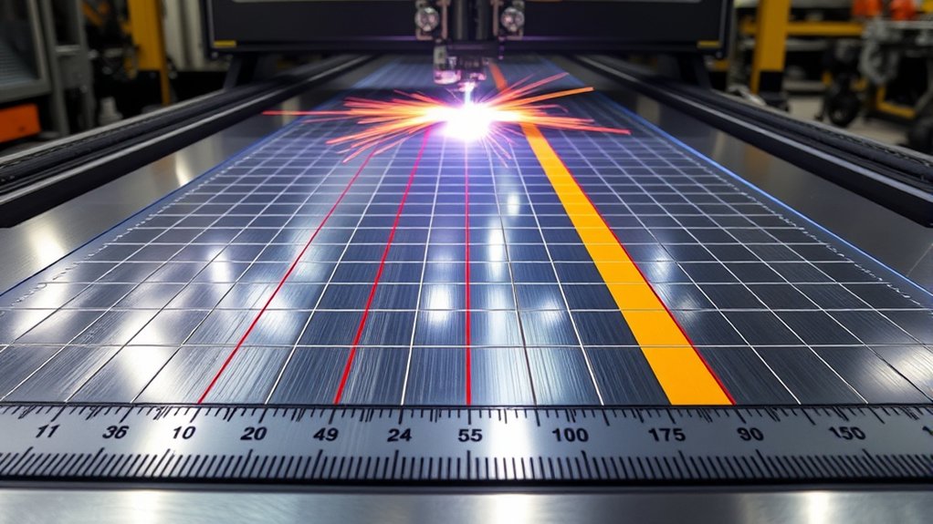
Clean, repeatable cuts come from controlling the full process rather than adjusting speed alone. For thin sheet or detailed parts, use the fine-cut consumable approved for your machine. These processes can create a narrower kerf, but they also require their own current, height, and speed values.
How to Dial In Plasma Cutting Speed
- Confirm the metal. Identify the alloy and measure the actual thickness with a gauge or caliper.
- Prepare the work area. Remove flammables, provide ventilation, support the plate, and attach the work lead to clean metal as directed by the manual.
- Inspect the system. Check the torch, lead, consumables, air filter, pressure, and input-power requirements.
- Load the exact chart row. Set amperage, cut height, initial pierce height, pierce delay, arc voltage, and speed.
- Make a straight test cut. Use matching scrap and allow the torch to reach steady motion before judging the edge.
- Inspect the result. Check penetration, dross type, top-edge rounding, bevel, kerf, heat tint, and distortion.
- Adjust one variable. Change speed first in small steps. If the defect remains, check consumables, standoff, gas flow, and current.
- Record the final setup. Save the material lot, thickness, consumable part numbers, current, speed, voltage, height, pressure, and observed consumable condition.
| Parameter | Starting Point | Why It Matters |
|---|---|---|
| Amperage | Exact value listed for the process and consumable | Controls available arc energy and usable speed range |
| Cut height or arc voltage | Manufacturer chart value | Affects bevel, kerf, arc stability, and consumable life |
| Initial pierce height | Often 120%–200% of cut height, but chart-specific | Keeps molten pierce spatter away from the nozzle |
| Pierce delay | Exact chart value for thickness | Allows full penetration before motion without holding the arc stationary too long |
| Kerf compensation | Use chart kerf as a reference, then measure a test part | Offsets the toolpath so finished dimensions remain accurate |
Safety Considerations in Plasma Cutting

Plasma cutting combines high voltage, intense light, hot metal, sparks, compressed gas, noise, and metal fumes. Read the machine’s safety manual before operating or servicing it. OSHA identifies burns, eye injury, electric shock, cuts, crushed fingers or toes, ultraviolet radiation, and metal-fume exposure among the hazards of welding and cutting work.
Warning: Never cut a sealed, pressurized, or previously used drum, tank, pipe, or container unless it has been professionally cleaned, tested, opened, and made safe for hot work. Keep sparks away from flammables, provide suitable ventilation, and never service the torch or power supply while energized.
Personal Protective Equipment
Wear PPE suitable for the machine, current, material, and work area:
- Eye and face protection: Use safety glasses with side shields under an approved cutting shield or helmet. OSHA’s eye-protection table lists a minimum shade 8 for light plasma arc cutting below 300 amps when the arc is clearly visible; follow the equipment manual and workplace requirements if they call for greater protection.
- Hand and body protection: Wear dry heat-resistant gloves, flame-resistant long sleeves, non-cuffed pants, and clothing that covers exposed skin.
- Foot protection: Use sturdy leather or heat-resistant safety footwear that protects against hot drops and sharp plate.
- Hearing protection: Use suitable ear protection when noise levels or the manufacturer’s guidance require it.
- Respiratory protection: Use ventilation and any respiratory protection required by the hazard assessment and applicable rules. A respirator is not a substitute for controlling fumes at the source.
Fume, Fire, and Material Hazards
Use local exhaust or other effective ventilation to keep fumes and gases within applicable exposure limits. Coatings, paint, plating, galvanized steel, stainless steel, and unknown scrap can release hazardous contaminants. OSHA guidance calls for extra controls for metals or coatings that may contain chromium, cadmium, lead, zinc, mercury, nickel, or other toxic substances.
Remove coatings and solvents from the heat-affected area when it is safe to do so, identify the base material, and review the safety data for the metal or coating. Do not cut near chlorinated solvent vapors. Keep a suitable fire extinguisher available, protect nearby openings and combustible surfaces, and inspect the area after cutting for smoldering material.
Handling Hot Cut Parts
Freshly cut parts, skeletons, slag, and offcuts can remain hot long after they stop glowing. Use pliers, tongs, lifting equipment, or other suitable tools instead of bare hands. Mark hot material, keep it away from walkways, and use correct lifting methods for large plate to prevent crush and back injuries.
Electrical Safety Measures
- Keep gloves, clothing, the floor, and the work area dry. Do not cut while standing in water.
- Inspect the power cord, torch lead, work lead, and connectors before use. Remove damaged equipment from service.
- Connect the work lead to clean metal as directed by the manual. The work lead is part of the cutting circuit and does not replace the equipment’s protective earth connection.
- Use the correct supply voltage, circuit protection, plug, extension-cord size, and generator capacity for the plasma cutter.
- Turn off, isolate, and lock out power before opening the power supply or servicing internal parts. Stored energy can remain after shutdown.
Water-Table and Underwater Cutting Safety
Water-table or underwater cutting must be approved by the plasma-system and table manufacturers. It is not a general capability of every CNC plasma cutter. Aluminum requires special attention because cutting aluminum alloys near or under water can generate hydrogen gas that may collect and explode.
The Hypertherm Safety and Compliance Manual says not to cut aluminum alloys under water or on a water table unless hydrogen accumulation is prevented through a documented risk assessment and mitigation plan. It also states that aluminum-lithium alloys must never be cut in the presence of water.
Enhancing Performance With Beacon-Powered Systems

Beacon is Hirebotics’ branded software platform for its cobot cutting systems; it is not a generic plasma-power technology or an industry standard. In a properly configured cell, the software can help operators program paths and manage process settings from a phone or tablet. Torch-height control and arc-voltage feedback can improve consistency when they are included and set up correctly.
Automation can maintain a steadier path and higher travel speed than manual cutting, but it does not override the plasma manufacturer’s cut chart. A claim such as “over 100 IPM” depends on material, thickness, current, consumables, motion limits, and the desired quality.
| Feature | Practical Benefit | Important Limit |
|---|---|---|
| App-based programming | Can simplify job setup and repeat paths without conventional CNC programming | The operator still needs a verified process and safe fixturing |
| Arc-voltage and height control | Can keep standoff more consistent over warped or uneven plate | Voltage must match the exact cut chart and calibrated system |
| Repeatable robot motion | Can improve consistency and throughput on repeated parts | Corners, small holes, reach, and acceleration still affect local speed |
Products Worth Considering

Rated voltage: 110/220V±15% 50/60HZ, Effective cutting range: 59"x98", Track rail size 84"x118"(X axis and Y axis)

High Quality Material: The guide wheel is made of high‑speed steel material, durable and long service life.The wheel has brass plating surface processing, not easy to rust and corrosion resistant

All-in-one CNC plasma cutting solution includes 4×4 CNC table, 60-amp cutter, CNC torch, and consumables
How to Read a Manufacturer’s Cut Chart
Start with the cut chart supplied for your exact model and revision. Then follow these steps:
- Select the material page. Choose mild steel, stainless steel, aluminum, or another approved conductive metal.
- Select the process and current. Confirm standard, fine-cut, high-definition, marking, or another process and the required amperage.
- Verify the gas. Use only the approved air or gas type, pressure, flow, and purity. Do not substitute flammable or oxidizing gases unless the system is specifically designed and approved for them.
- Match the thickness. Measure the plate and use the exact row. Gauge numbers can differ by material.
- Install the listed consumables. Confirm every part number and orientation before setting speed.
- Enter cut height and pierce height. On charts that show pierce height as a percentage, the percentage is relative to cut height.
- Enter pierce delay. Too little delay can begin motion before the arc exits the bottom; too much delay can damage the hole and consumables.
- Choose the quality target. Use “Best Quality” for edge finish and dimensional work. Use “Highest Production” only when the extra speed and possible quality tradeoff are acceptable.
- Set arc voltage for mechanized cutting. Use the chart as the starting value, then follow the torch-height-control procedure for voltage calibration and consumable wear.
- Enter kerf compensation. Treat published kerf as a reference and verify it with a measured test part before a precision run.
- Confirm gas flow and pressure. Restrictions, leaks, wet air, or the wrong regulator setting can invalidate the chart.
- Run and document a test. Record any approved adjustment so future operators can repeat the setup.
Note: Arc voltage is not a universal safety or performance number. It is a process setting linked to torch height, lead length, consumable wear, and the specific mechanized system.
Frequently Asked Questions
What Is the Lifespan of a Plasma Cutting Machine?
There is no fixed lifespan. A well-maintained power supply can remain useful for many years, while electrodes, nozzles, cartridges, shields, filters, torch leads, and cooling-system parts are wear items. Service life depends on duty cycle, air quality, starts, environment, maintenance, and whether the machine is operated within its ratings.
How Do Environmental Conditions Affect Cutting Speed?
Temperature, altitude, humidity, dust, and input-power quality can affect gas density, cooling, air-system performance, and arc stability. Follow the operating limits in the manual. Use clean, dry, oil-free air where specified and reduce the duty cycle or correct the air supply if the machine overheats or the pressure drops during a cut.
Can Plasma Cutters Be Used Underwater?
Some mechanized plasma systems and tables are designed for cutting over or under water, but only under the manufacturers’ instructions. Do not assume a handheld or CNC system is suitable. Aluminum near water can create an explosive hydrogen hazard, and aluminum-lithium alloys must not be cut in the presence of water.
What Maintenance Is Required for Optimal Machine Performance?
Inspect consumables, the torch lead, work lead, power cord, air filters, regulator, cooling passages, and grounding or bonding connections at the intervals in the manual. Drain moisture, correct air leaks, keep vents clear, replace damaged parts, and verify torch alignment before troubleshooting speed.
How Do Plasma Cutters Compare to Laser Cutters in Speed?
There is no single thickness where plasma is always faster. The result depends on laser power, plasma current, material, thickness, assist gas, motion system, piercing time, and required edge quality. Fiber lasers are often very fast on thin sheet and fine features, while plasma can be highly productive and cost-effective on plate. Compare current cut charts for the exact machines.
What Happens If Plasma Cutting Speed Is Too Slow?
A slow speed increases heat input and can widen the kerf, round the top edge, create top spatter, distort thin plate, and leave a large bubbly deposit on the bottom. Increase speed in small steps after confirming that amperage, standoff, and consumables match the chart.
How Do I Convert IPM to Millimeters per Minute?
Multiply inches per minute by 25.4. For example, 80 IPM equals 2,032 mm/min. To convert mm/min to IPM, divide by 25.4.
Conclusion
A plasma cutting speed chart works best as a controlled starting point. Match the exact machine, material, thickness, process, current, consumables, gas, height, and quality target before entering the listed IPM or mm/min. Then make a test cut and tune one variable at a time. This approach produces cleaner edges, more accurate parts, less dross, and longer consumable life without relying on unsafe or misleading universal settings.
Sources
- Hypertherm Powermax45/65/85/105 SYNC Cut Charts Guide, Revision 4 — cut-chart columns, 45/85/105-amp speed examples, pierce settings, kerf, and best-quality versus highest-production data.
- Hypertherm: Troubleshooting Too Much Dross — symptoms and adjustments for high-speed and low-speed dross.
- Hypertherm Safety and Compliance Manual — electrical, fume, fire, gas, water-table, and aluminum-cutting hazards.
- OSHA: Welding, Cutting, and Brazing Hazards and Solutions — burns, eye hazards, electric shock, fumes, and related controls.
- OSHA: Eye Protection Against Radiant Energy During Welding and Cutting — minimum filter-shade guidance for plasma arc cutting.
- Hirebotics: Beacon-Powered Plasma Cutting — product-specific description of the Beacon platform and Cobot Cutter workflow.