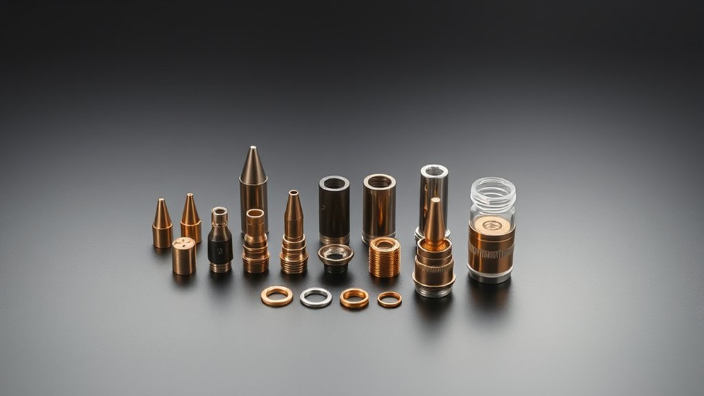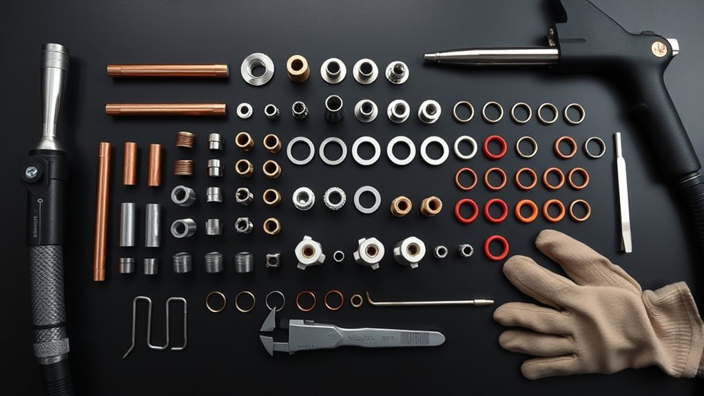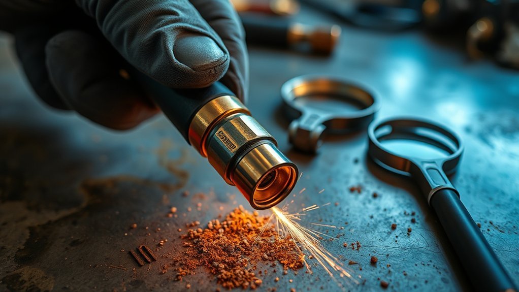
Worn plasma cutter consumables usually show visible or performance clues before they fail completely. The safest way to catch them is to shut the system down, inspect the electrode, nozzle, swirl ring, shield, and retaining cap, then compare what you find with the wear limits in your torch manual. Changes in cut quality, starting, sound, or arc appearance can support the diagnosis, but they should not replace a physical inspection.
Quick Answer
Replace plasma cutter consumables when the electrode pit exceeds your torch manual’s limit, the nozzle hole becomes oval or damaged, the swirl ring cracks or has blocked gas holes, or the shield and retaining cap show permanent damage. Hard starts, wider kerf, extra bevel, and rising dross are warning signs, but first rule out setup, grounding, and air-supply problems.
Last updated: July 20, 2026
Key Takeaways
- There is no universal electrode pit-depth limit. Use the limit for your exact torch, electrode, and amperage.
- Replace a nozzle when its center hole is no longer round or when it has erosion, a notch, a slot, missing material, or blocked gas passages.
- Clean reusable parts gently with a lint-free cloth and clean, dry compressed air. Replace cracked, burned, melted, or deformed parts.
- Treat hard starts, bevel, dross, slow cutting, and arc changes as diagnostic clues, not proof that one specific consumable has failed.
- Clean, dry, oil-free air, correct torch height, correct amperage, and proper assembly can prevent premature wear.
At a Glance
| Time Required | 5–15 minutes for a routine inspection |
| Difficulty | Beginner to intermediate, provided you follow the operator manual |
| Tools Needed | Operator manual, clean lint-free cloth, good lighting, magnifier, clean dry compressed air, and the maker’s pit-depth gauge if specified |
| Cost | Inspection is free; replacement cost varies by torch model and consumable type |
Warning: Turn the plasma cutter off, disconnect electrical power and the gas supply, and let hot parts cool before removing torch components. Never disassemble a torch while the system is energized. Stop using a torch with cracks, exposed wires, damaged leads, or a defective safety trigger.
What’s in This Article
- Before You Inspect Plasma Cutter Consumables
- Visual Clues on Electrodes
- Nozzle Wear Patterns
- Swirl Ring Integrity
- Shield and Retaining Cap Checks
- Performance Red Flags
- Height, Arc Appearance, and Sound Cues
- Simple Bench Tests
- How to Clean, Replace, and Reassemble Parts
- Life Tracking and Baselines
- When to Replace vs. Clean
- Cartridge-Style Consumables
- Frequently Asked Questions
Before You Inspect Plasma Cutter Consumables
Consumable wear is only one possible cause of a poor plasma cut. Speed, amperage, torch angle, torch-to-work distance, pierce height, air pressure, air contamination, grounding, material condition, and incorrect part selection can create similar symptoms. Start with a safe, repeatable inspection instead of replacing parts at random.
- Shut down safely: Turn off the system, disconnect input power, isolate the gas supply, and wait for the torch to cool. Follow the lockout steps in your operator manual.
- Confirm the correct parts: Match every consumable part number and amperage rating to the cut chart for your torch and process.
- Remove parts over a clean surface: Keep the consumables in order on a clean, lint-free cloth so metal dust cannot enter the torch.
- Inspect all parts as a system: Examine the shield, retaining cap, nozzle, electrode, swirl ring, O-rings, torch body, electrode seat, and vent holes.
- Compare with the manual: Use the wear illustrations and dimensional limits for your exact model. Do not apply another torch’s pit-depth number to yours.
Note: Some torches use a traditional five-piece stack, while newer systems may use a sealed or single-piece cartridge. Do not try to separate a cartridge that the manufacturer designed as one replaceable unit.
Visual Clues on Electrodes: Hafnium Pits, Divots, and Discoloration
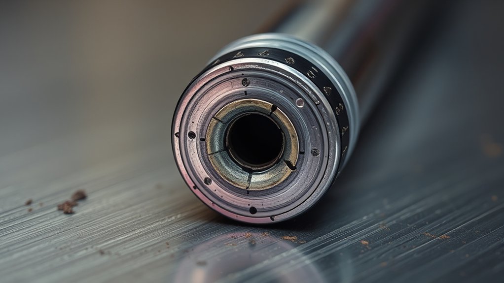
The electrode face often shows wear before the cut becomes unacceptable. Inspect the hafnium emitter in the center for a pit that is too deep, unusually wide, rough-edged, off-center, or surrounded by a badly eroded electrode face.
Use the pit-depth method specified by the torch maker. A purpose-made gauge gives a more reliable reading than judging by eye. Measure from the same reference point each time and keep the gauge square to the electrode face.
Electrode Pit Depth Is Model-Specific
A 1/16-inch limit applies to some Powermax consumables, but it is not universal. Official Hypertherm examples include a 0.8 mm limit in an older Powermax troubleshooting guide, 1 mm for a Powermax45 XP electrode, and general XPR guidance ranging from 1 mm to 1.5 mm according to amperage. Your manual may give a different value. Check the exact electrode, torch, and process before deciding that a part is still usable.
The correct replacement point is the wear limit in your operator manual, not one universal pit-depth number.
Replace the electrode when the pit exceeds the manual’s limit or when the pit extends beyond the hafnium, becomes asymmetrical, or leaves a rough and damaged face. A severely overused electrode can release molten material into the nozzle and start a chain of damage through the consumable stack.
Heat tint alone does not prove that an electrode has failed. However, heavy straw, blue, black, burned, or melted areas can support a diagnosis of overheating, low gas flow, cooling trouble, or severe overuse. Stop and inspect the entire system rather than relying on color alone.
For many torch families, the manufacturer recommends replacing the nozzle and electrode together because they wear as a matched pair. Follow your model’s instructions.
Nozzle Wear Patterns: Out-of-Round Orifices and Radial Grooves

The nozzle constricts and focuses the plasma arc, so a small change in the center hole can affect kerf width, bevel, dross, and edge consistency. Inspect the orifice under bright light and magnification. It should remain round, centered, and free of notches or missing material.
Out-of-Round Indicators
Replace a nozzle when its hole becomes oval, egg-shaped, noticeably enlarged, notched, slotted, or otherwise non-circular. Also replace it when the face or interior shows severe erosion, missing copper, cracking, or blocked gas holes.
A visual comparison with a new nozzle of the same part number is often useful. If your operator manual supplies an orifice measurement or gauge, use that method. Do not force a drill bit, wire, needle, or improvised tool through the hole because it can scratch or enlarge the precision orifice.
Wandering arc marks, uneven edge bevel, a wider kerf, and a sudden need to reduce speed may accompany nozzle wear. These clues strengthen the diagnosis, but you should still check torch height, travel speed, amperage, gas flow, torch squareness, and cut direction.
Radial Grooves, Slots, and Keyhole Damage
Grooves, slots, or keyhole-shaped erosion show that the nozzle has lost its intended geometry. Replace the nozzle rather than trying to polish the damage away.
The pattern can have more than one cause. Low pressure in the plasma chamber, gas leaks, low gas flow, incorrect assembly, double-arcing, arc stretching, piercing too close to the plate, contact with the workpiece, or excessive amperage can all damage a nozzle. Use the shape of the failed part as a clue, then verify the setup against the cut chart and service manual.
Impact on Cut Quality
As the nozzle loses roundness, the arc can lose focus and become less stable. You may see a wider kerf, changing taper, rough striations, heavier dross, poor hole quality, or inconsistent edge geometry. The table below helps you separate likely consumable wear from setup faults.
| Symptom | Possible Consumable Cause | Check Before Replacing Parts |
|---|---|---|
| Wider or uneven kerf | Enlarged or oval nozzle | Torch height, speed, amperage, torch squareness |
| Uneven bevel | Damaged nozzle or unstable gas swirl | Cut direction, torch angle, height control, worn motion components |
| Heavy dross | Worn nozzle or electrode | Travel speed, amperage, air pressure, material coating or rust |
| Arc flutter or cut dropout | Mixed consumable wear or blocked gas paths | Ground connection, air supply, torch lead, fault codes |
Swirl Ring Integrity: Cracks, Warping, and Gas Path Blockage
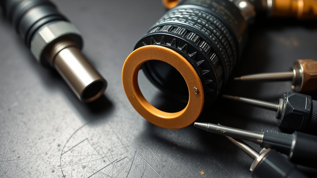
The swirl ring controls the gas pattern around the electrode and nozzle. Cracks, chips, burns, deformation, damaged O-rings, or blocked gas holes can disturb that flow and shorten the life of nearby parts.
- Inspect the surface and bore: Use strong light to look for cracks, arc burns, melted edges, chips, distortion, or excessive wear.
- Inspect every gas hole: Confirm that holes are open and retain their intended shape. Do not enlarge them with wire or a drill.
- Check the fit: The electrode should fit and move as the manual describes, and the ring should seat correctly without rocking or forcing.
- Check O-rings: Replace torn, cut, flattened, or missing O-rings. Remove excess lubricant that could block a gas path.
Use clean, dry compressed air to remove loose debris if the manufacturer permits it. Replace the swirl ring when it is cracked, chipped, burned, deformed, or still blocked after safe cleaning. An inconsistent start, wandering kerf, or rising dross can point you toward the ring, but these symptoms can also come from gas pressure, air contamination, nozzle wear, or incorrect assembly.
Shield and Retaining Cap Checks: Spatter, Warpage, and Thread Damage
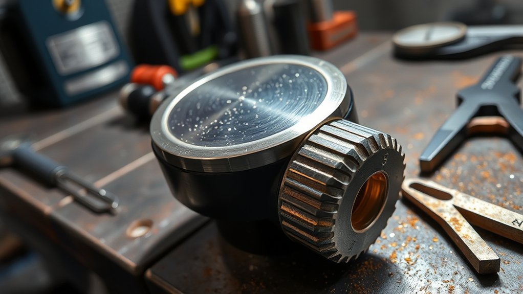
The shield and retaining cap protect the internal stack and help maintain the intended gas flow. They may last longer than the electrode and nozzle, but they still need regular inspection.
Check the shield for stuck molten metal, erosion, cracks, missing material, a non-circular center hole, blocked ports, and damaged O-rings. Light spatter can often be removed if the shield itself remains undamaged. Replace it when cleaning cannot restore open ports and correct geometry.
Inspect the retaining cap for burns, cracks, distortion, damaged threads, cross-thread marks, debris, and damaged sealing surfaces. A cap that cannot hold the stack in correct alignment should be replaced.
Clean reusable surfaces with a lint-free cloth and clean, dry compressed air. Use only the lubricant and amount specified by the manufacturer. Too much O-ring lubricant can attract metal dust or block gas passages.
Pro Tip: Keep a new nozzle, electrode, and other high-wear parts beside the used ones during inspection. A side-by-side comparison makes oval holes, lost edges, heat damage, and deformation easier to see.
Performance Red Flags: Arc Starts, Bevel, Dross, and Cut Speed Changes
Performance changes can tell you when to stop and inspect, but they rarely identify one failed part by themselves. Record what changed, then check consumables and setup in a logical order.
Hard Starts and Misfires
Recurring hard starts, pilot-arc hesitation, sputtering, double-firing, or an arc that lights and quickly dies can come from a worn electrode or nozzle. They can also come from excessive preflow pressure, contaminated gas, low or unstable air pressure, incorrect assembly, a damaged swirl ring, a poor work connection, torch-lead damage, or a system fault.
Do not keep slowing your travel speed or repeatedly pulling the trigger to force the machine to cut. Stop, check the display for fault codes, inspect the ground clamp and return path, verify the gas supply, and inspect the torch stack. If a fresh, correct nozzle-and-electrode pair does not solve the problem, follow the service manual or contact a qualified technician.
Bevel and Dross Increase
A sudden increase in bevel or dross can indicate that the arc has lost focus, but speed and height errors are common causes too. High-speed dross, low-speed dross, and top spatter have different setup causes, so compare the cut edge with the troubleshooting illustrations in your manual.
Inspect the nozzle for roundness, then check the electrode pit, swirl ring, shield, torch squareness, travel direction, cut height, pierce height, amperage, air pressure, and material thickness. Replace worn parts only after you confirm that the process settings match the cut chart.
Cut Speed and Kerf Changes
If a cut that normally runs cleanly at a known setting suddenly needs less speed, leaves a wider kerf, or fails to sever the same material, inspect consumables and the air supply. A worn nozzle can weaken focus, while a worn electrode can reduce stable transfer. Low input voltage, inadequate air flow, an air leak, or a dirty filter can create similar behavior.
Height and Sound Cues: Arc Appearance, Standoff, and Audible Indicators
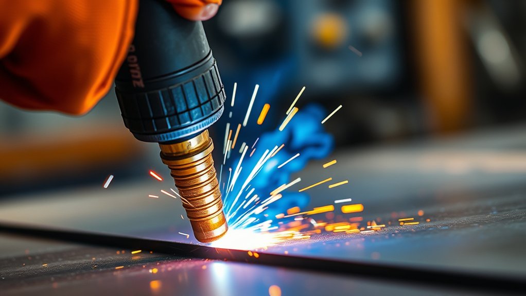
Experienced operators often notice changes in torch sound, arc appearance, cut speed, or torch height before they remove the parts. Use those changes as an early warning, not as a color-coded diagnosis.
A healthy process should sound and behave consistently for the same machine, consumables, material, thickness, and settings. Sputtering, changing pitch, harsh chatter, flicker, arc wandering, or repeated loss of transfer means you should stop and investigate.
Incorrect standoff can rapidly damage a nozzle. Piercing or cutting too close can drive spatter into the front of the torch and encourage double-arcing. Excessive height can widen the kerf, increase bevel, and reduce arc density. Use the pierce-height and cut-height values in the manufacturer’s cut chart instead of estimating by eye.
Arc color can change with the gas, process, material, filters, and camera or eye protection. Do not assign a universal meaning to green, purple, orange, white, or blue. Compare only against the normal appearance of your verified setup, and confirm any suspected wear by inspecting the parts.
Simple Bench Tests: Magnification, Depth Gauges, and Reference Cuts
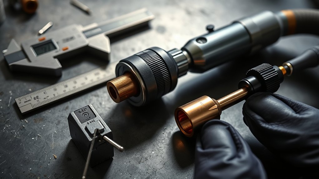
You do not need laboratory equipment for a useful routine inspection. Good lighting, a magnifier or phone macro lens, a clean surface, and the correct pit-depth gauge will catch most common wear.
- Photograph new parts: Record the nozzle hole, electrode face, swirl ring, shield, and cap from the same angle and lighting you will use later.
- Inspect under magnification: Look for non-round holes, notches, cracks, rough pits, missing material, blocked passages, and damaged O-rings.
- Measure only with approved methods: Use the maker’s pit gauge or specified measuring tool. Avoid improvised probes that can damage the nozzle.
- Reassemble correctly: Install the parts in the order and orientation shown in the manual, using the specified torque or finger-tight instruction.
- Make a controlled reference cut: After restoring power and gas, cut the same clean material at the same thickness and verified settings. Compare kerf, bevel, dross, sound, and start behavior with your baseline.
Do not “test fire” a torch while parts are loose, removed, or improperly installed. Never point a hand torch toward yourself or another person.
Clean, Replace, and Reassemble Without Causing Damage
Cleaning helps only when a part remains within its wear limit and retains its intended shape. It cannot restore an oval nozzle, a deep electrode pit, cracked plastic, melted edges, damaged threads, or a distorted gas passage.
| Part | Usually Safe to Clean | Replace When |
|---|---|---|
| Electrode | Loose surface dust only | Pit exceeds the model limit; pit is rough, wide, off-center, or beyond the emitter; face is severely damaged |
| Nozzle | Loose debris on undamaged surfaces | Hole is oval, enlarged, notched, slotted, blocked, cracked, or missing material |
| Swirl ring | Loose dirt that clears with approved cleaning | Cracked, chipped, burned, deformed, or blocked; O-ring is damaged |
| Shield | Removable spatter with no base-part damage | Center hole is not round; ports remain blocked; material is cracked, eroded, melted, or missing |
| Retaining cap | Dust and loose debris | Cracked, burned, distorted, cross-threaded, or unable to seat the stack correctly |
Use a clean, lint-free cloth for surfaces and clean, dry compressed air for loose debris when your manual allows it. Some manufacturer procedures permit rinsing specific consumables with clean tap water, but you should never use contaminated cutting-table water. Dry every part completely before assembly.
Lubricate only the O-rings that the manual identifies. Use the specified silicone lubricant and apply only a thin film, often described as enough to make the O-ring look shiny. Remove visible buildup. Never substitute general grease unless the manufacturer explicitly approves it.
Reassemble on a clean surface. Confirm orientation, correct part numbers, correct torque, and the required cap tightness. Some retaining caps are finger-tight only; overtightening can compress or damage internal parts.
Life Tracking and Baselines: Parts Count, Amps, Material, and Air Quality
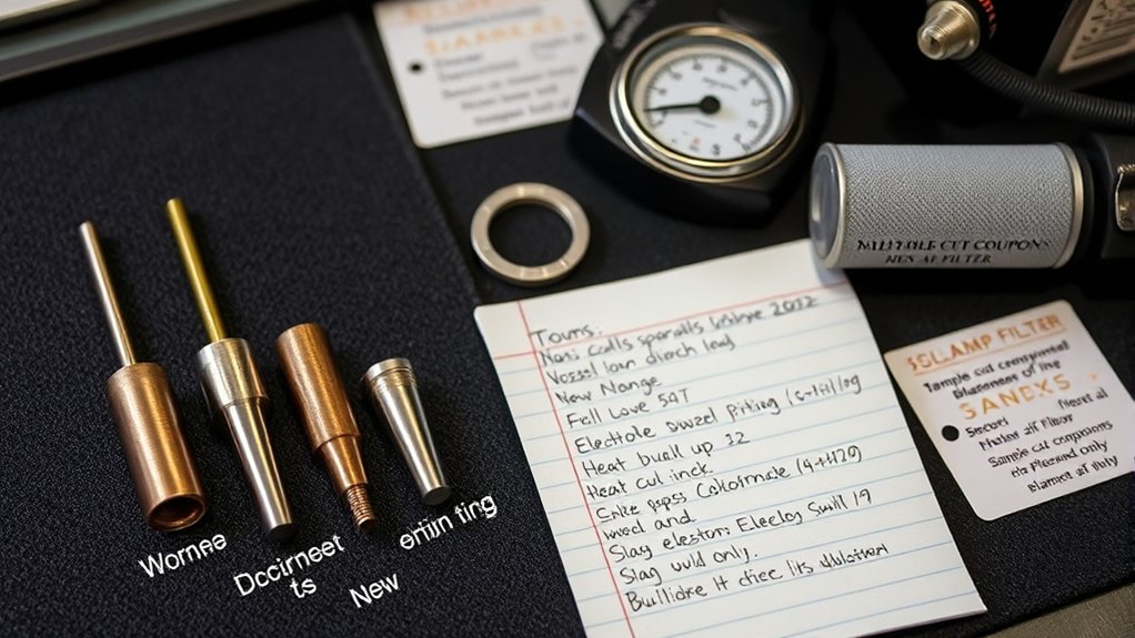
A life log helps you tell normal wear from a sudden process problem. Consumables do not have one reliable hour rating because starts, pierces, arc-on time, amperage, material, thickness, cutting technique, air quality, and cooling conditions all affect life.
Track the following:
- torch model and consumable part numbers;
- installation and replacement dates;
- pierce count, start count, cut count, and arc-on time when available;
- amperage, material type, thickness, process, and average cut length;
- torch height, pierce height, travel speed, and fault codes;
- air pressure, filter condition, tank-drain events, moisture, and oil contamination;
- operator, observed wear pattern, and cut-quality change;
- photos of the failed electrode, nozzle, swirl ring, shield, and cap.
Review the log for sudden changes. Rapid pit growth, repeated nozzle ovalization, short cartridge life, or recurring hard starts often point to an upstream issue rather than a bad batch of parts.
Air Quality and Premature Wear
Air-plasma systems need enough clean, dry air at the pressure and flow specified by the manufacturer, with oil and particulate contamination controlled. Water, oil, dirt, and other contamination can reduce cut quality and consumable life and may damage the torch or internal components.
Drain the compressor tank, inspect the machine’s filter bowl and element, repair air leaks, and add suitable external filtration or drying when humidity or compressor contamination overwhelms the built-in filter. Do not install an oiled air-tool line upstream of a plasma cutter unless the air is properly separated and filtered for the plasma system.
When to Replace vs. Clean: Practical Limits and Preventing Catastrophic Failures
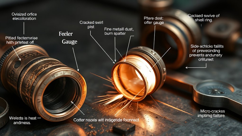
Replace a part when it exceeds the dimensional or visual limit in the manual, no longer retains its precision geometry, or has permanent physical damage. Clean only contamination that can be removed without changing the part’s shape.
Do not polish an over-pitted electrode, reshape a nozzle hole, straighten a cracked swirl ring, chase damaged cap threads, or reuse a burned O-ring. These actions can hide damage without restoring safe gas flow or arc alignment.
Severely overused consumables can ruin a workpiece and damage the torch. Replace the electrode and nozzle as a pair when your manual requires it. If both fail rapidly, inspect air quality, gas pressure, cooling, amperage, torch height, piercing practice, assembly, and the torch body before installing another set.
Stop using the system and seek qualified service when you find a cracked torch body, exposed conductors, a damaged trigger, burned internal seats, damaged torch leads, repeated internal arcing, persistent gas leaks, or fault codes that remain after approved maintenance.
Products Worth Considering

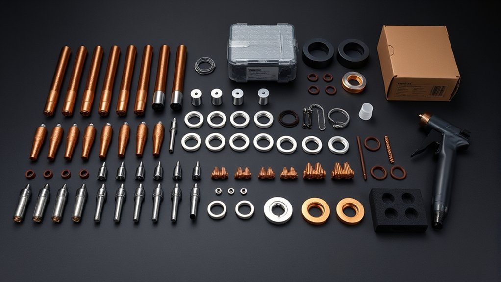
Package Include: 10 Shield Cups, 50 Nozzles, 20 Swirl Baffle, and 30 Electrodes.

[Achieve Precise Cuts] PT31 Plasma Cutting Consumables – Your Essential Tool for Efficient Cutting! Whether you're working with sheet metal, steel, or any other material, superior cutting performance ensure clean, accurate, and smooth cuts.

High-Quality Material:Made of high quality material to ensure a longer lifespan and superior performance.
Cartridge-Style Consumables
Single-piece cartridge systems require a different inspection routine. Keep the cartridge intact and follow the system’s lock or safety procedure before removing it. Inspect the integrated nozzle orifice for roundness, notches, or an egg-shaped opening, and inspect the outer shield and retaining area for excessive wear or damage.
Some cartridge systems provide an end-of-life light or fault code. Replace the cartridge when the system indicates end of life, when cut quality falls below your requirement, or when physical inspection shows damage. Do not bypass end-of-life protection or reuse a cartridge that the system identifies as spent.
Products Worth Considering
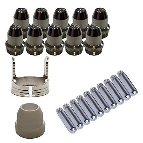
Only Compatible with BROWN Color Lotos LTP5800D , LTP5000D, LTPDC2000D.

⚡【Precision Compatibility】 Exact fit for YESWELDER CUT 55DS Pro & 65DS (2019-2024 models). Replaces OEM# IPT40-55DS/65DS.

2pcs 9-0097 start cartridge
Frequently Asked Questions
Is 1/16 inch the replacement limit for every plasma electrode?
No. Some Powermax guidance uses 1.6 mm, or about 1/16 inch, but other official manuals specify 0.8 mm, 1 mm, 1.25 mm, or 1.5 mm depending on the torch, electrode, and amperage. Use the wear limit in the manual for your exact system.
Do ambient temperature or humidity affect consumable wear?
Humidity can increase the moisture entering a compressed-air system, which can reduce cut quality and consumable life. In hot or humid conditions, drain the compressor, maintain filters, and add an appropriate dryer or external filtration system when required. Follow the machine’s environmental and gas-quality specifications.
Can poor grounding mimic worn consumables?
Yes. A dirty, loose, or poorly placed work clamp can cause difficult starts, arc dropouts, incomplete cuts, and unstable performance. Clean the contact area, inspect the cable, and verify the return path before blaming the torch parts.
How does duty cycle influence consumable lifespan?
Duty cycle is primarily a machine heat limit, not a direct consumable replacement gauge. Exceeding it can overheat the system, while excessive amperage, many starts, long pilot arcs, poor cooling, and inadequate gas flow can also shorten part life. Respect the rated duty cycle and track actual wear.
Are aftermarket consumables comparable to OEM parts?
Quality and dimensional accuracy vary, so there is no universal answer. Use parts approved for your exact torch, verify every part number and amperage, and follow warranty requirements. Stop using any batch that causes abnormal starts, rapid wear, poor fit, gas leakage, or declining cut quality.
Should I replace the electrode and nozzle together?
Many torch manuals recommend replacing them as a pair because they wear together and one failed part can damage the other. Follow the instructions for your model rather than assuming that every torch uses the same rule.
What data should I log for recurring wear?
Record the torch model, consumable part numbers, batch, install date, replacement date, starts, pierces, arc-on time, amperage, material, thickness, air pressure, filter condition, operator, fault codes, and wear photos. Match each replacement to changes in kerf, bevel, dross, starting, and speed.
When should I replace a one-piece plasma cartridge?
Replace it when the system reports end of life, when cut quality no longer meets your needs, or when the integrated nozzle, shield, or retaining area shows excessive wear or damage. Follow the cartridge maker’s inspection and recycling instructions.
Safety Disclaimer: This article provides general plasma cutter inspection and maintenance information. Your operator and service manuals control. Wear the required eye, face, hearing, respiratory, hand, and protective clothing for the job. Disconnect power and gas before handling torch parts, and use a qualified technician for electrical faults, internal repairs, persistent gas leaks, or torch damage.
Sources
- Hypertherm: Powermax Preventive Maintenance — shutdown steps and inspection criteria for torch parts and consumables.
- Hypertherm XPR170: Examine the Electrode for Emitter Wear — model- and amperage-specific pit-depth guidance.
- Hypertherm XPR460: Examine the Consumable Parts — clean-versus-replace criteria for shields, nozzles, swirl rings, caps, and O-rings.
- Hypertherm: Extending Parts and Consumables Life — wear patterns, gas-flow problems, nozzle damage, and troubleshooting.
- Hypertherm: Air Filtration for Air-Plasma Systems — the effect of moisture and air quality on consumable life.
- Hypertherm: When to Change Powermax SYNC Cartridges — cartridge inspection and end-of-life indicators.
Conclusion
Good consumable inspection keeps cut quality predictable and helps prevent torch damage. Check the electrode against the correct model-specific pit limit, replace any nozzle that has lost its round precision opening, and inspect the swirl ring, shield, retaining cap, O-rings, and torch body for permanent damage or blocked gas paths.
Use hard starts, bevel, dross, kerf width, speed, sound, and arc appearance as early warning signs, then rule out setup, grounding, air pressure, contamination, and height problems. Clean only reusable parts, assemble the stack exactly as the manual shows, and track wear over time. When a part reaches its limit, replace it before the failure spreads through the torch.