Clean plasma cuts depend on four settings working together: amperage, air pressure, tip size, and travel speed. Match those settings to steel thickness, then check the kerf, spark angle, and dross before you cut a full part. For example, 1/16 in steel often cuts well at 15–20 A and 50–55 psi, while 1/4 in steel usually needs 40 A and 65–75 psi.
What’s in This Article
- Power and Air Settings for Common Steel Thicknesses
- Understanding Kerf, Tip Size, and Consumable Selection
- Setup Tips to Minimize Warping on Thin Sheet
- Recommended Cut Speeds and Pierce Delays by Thickness
- Duty Cycle Considerations for 40 Amp Machines
- Material-Specific Notes: Mild Steel, Stainless, and Aluminum
- Safety Essentials and Best Practices During Cutting
- Frequently Asked Questions
- Final Cutting Tips for Clean, Repeatable Results
Quick Answer
For a 40 amp plasma cutter, start with 15–20 A for 1/16 in steel, 21–30 A for 1/8 in steel, 31–40 A for 3/16 in steel, and 40 A for 1/4 in steel. Keep air dry and oil-free, hold the correct standoff, and adjust speed until sparks trail below the plate at a slight angle.
Key Takeaways
- Match amperage and air pressure to steel thickness before you tune travel speed.
- Use clean, dry air to protect the torch, stabilize the arc, and reduce dross.
- Choose the right tip or FineCut consumables when you need a narrower kerf.
- Control heat on thin sheet with firm clamps, fast travel, and short pierce time.
- Respect the duty cycle so the machine and consumables do not overheat.
Power and Air Settings for Common Steel Thicknesses
Set amperage and air pressure to match steel thickness. The arc must cut through the plate and push molten metal out of the kerf without leaving heavy dross.
Use these settings as starting points for mild steel:
- 1/16 in (1.6 mm): 15–20 A with 50–55 psi.
- 1/8 in (3.2 mm): 21–30 A with 55–60 psi.
- 3/16 in (4.8 mm): 31–40 A with 65–70 psi.
- 1/4 in (6.4 mm): 40 A with 65–75 psi.
Check your machine manual before you cut. Torch design, consumables, input power, and compressor output can change the best setting.
Keep the air supply dry and oil-free to stabilize arc voltage and improve plasma cutting efficiency.
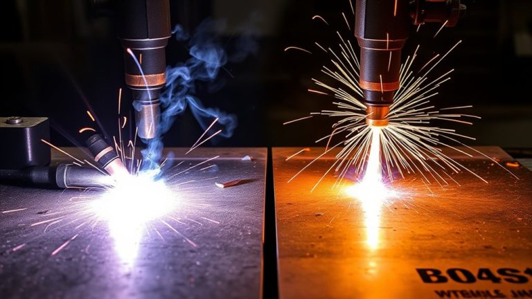
Watch the cut as you move. A near-vertical kerf face, low top spatter, and sparks trailing 10–15 degrees under the plate usually point to good settings.
If dross builds up or the arc stumbles, increase pressure within the listed range before you add amperage. If the edge bevels or the cut fails to separate, raise amperage in small steps.
Log your settings by thickness, nozzle class, shop temperature, and humidity. A simple log helps you repeat clean cuts later.
Products Worth Considering

【Product Name】1/4" NPT Air Pressure Filter/Regulator Unit
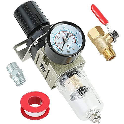
BRASS FILTER ELEMENT - Filtering moisture and fine particles to get clean and dry air which prevents damage to air tools, spray guns and pneumatic equipment. The filter element is brass that provide higher efficient filtration and long lifetime than the fiber one.

1/4" NPT Semi-Auto Drain FILTER + REGULATOR COMBO — removes water, oil and dust from your compressed air line to protect pneumatic tools, air compressor and spray equipment.
Understanding Kerf, Tip Size, and Consumable Selection
Kerf means the width of material the arc removes. You control it with amperage, air pressure, travel speed, tip orifice size, and consumable type.
A 40 amp plasma cutter on mild steel often creates a kerf near 0.035 in when you use matched settings and a standard tip. Treat that figure as a starting point, not a guarantee.
Plan your lead-ins, offsets, and part layout around the expected kerf. Small parts and tight slots need more care than long straight cuts.
Products Worth Considering

10 pcs TIPS (Extended) /10 pcs ELECTRODE (Extended) /10 pcs SHIEDED-CUP/10 pcs GAS RING

[Achieve Precise Cuts] PT31 Plasma Cutting Consumables – Your Essential Tool for Efficient Cutting! Whether you're working with sheet metal, steel, or any other material, superior cutting performance ensure clean, accurate, and smooth cuts.

Compatible with: suitable for PTM-60 IPT-60 IPTM-60 PT40 IPT-40 plasma torch, CUT 55 MP, CUT55 NHF, CUT65DS Plasma Cutter
Kerf Width Factors
Tip size, amperage, and consumable type drive most kerf changes. Larger tips widen the jet and remove more metal. Smaller tips tighten the arc and improve detail.
Higher amperage adds heat and can widen the melt zone. Lower amperage can narrow the cut, but too little current may cause arc instability.
FineCut consumables can narrow the kerf on thin sheet and help with detailed work. Use them only within the amp and thickness range the manufacturer gives for your torch.
Tip Orifice Sizing
The nozzle orifice sets the arc diameter and energy density. For many 40 amp machines, a 0.9 mm tip works well near 31–40 A and 65–70 psi.
Larger orifices can widen the kerf and soften edge detail. Smaller or FineCut orifices can tighten the kerf on thin stock when you match them to the correct current.
| Tip/Consumable | Setpoints (A/psi) | Typical Kerf |
|---|---|---|
| 0.9 mm Standard | 31–40 A / 65–70 psi | ~1.2–1.6 mm |
| FineCut | 28–35 A / 60–65 psi | ~0.8–1.1 mm |
| Oversize (1.0 mm) | 36–40 A / 70–75 psi | ~1.6–2.0 mm |
Copper and other highly conductive metals often need more power and slower tuning than mild steel. Check the torch chart before you cut copper, brass, or other nonferrous metals.
Consumable Lifespan Tips
Consumables last longer when you match the tip, amperage, pressure, standoff, and material thickness. A worn tip grows out of round, starts poorly, and can increase bevel.
Too much current can erode the nozzle and electrode faster. Low air pressure can cause dross and double-arcing, while too much pressure can widen the kerf and hurt edge quality.
Inspect parts before long cuts. Replace the nozzle and electrode as a pair when the arc starts to wander or cut quality drops.
Pro tip: Keep a small cut log with tip size, amps, psi, standoff, speed, and dross notes for each material.
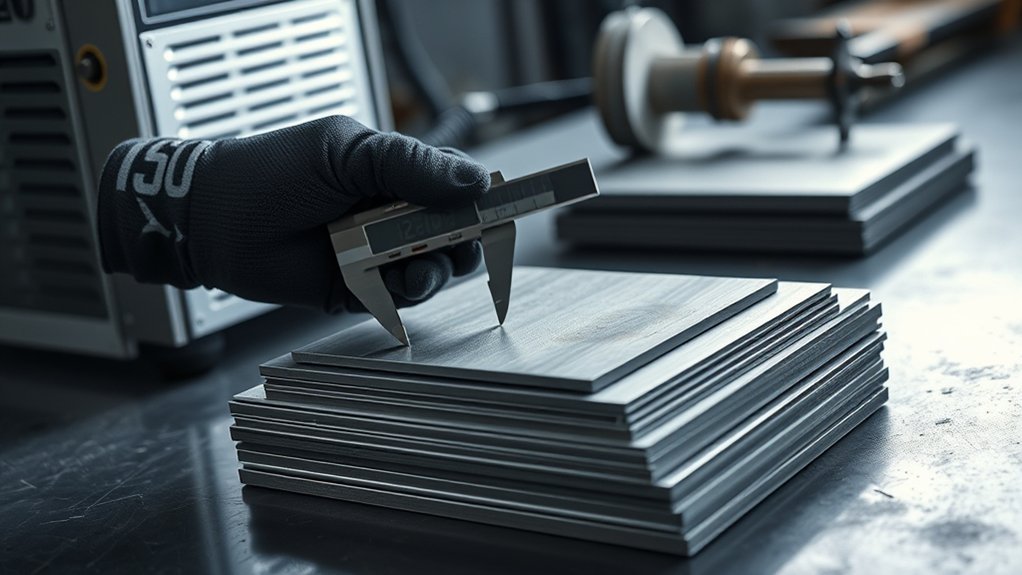
Setup Tips to Minimize Warping on Thin Sheet
Thin sheet warps when heat builds faster than the metal can shed it. Control restraint, heat input, and arc focus before you strike the arc.
Clamp the sheet near the cut path and along the edges. Do not stack sheets, because trapped heat can damage the bottom surface and make dross worse.
Move fast enough to limit dwell, avoid extra pierces, and use FineCut consumables when the job needs a narrow kerf. Match amperage to thickness, because too much current widens the cut and adds heat.
| Control | Specification/Target |
|---|---|
| Restraint | Full-contact clamps within 25–50 mm of path |
| Amperage | Match chart for alloy/thickness at ≤40 A |
| Standoff | 1.0–1.5 mm, or use torch height control when available |
| Travel speed | High enough to form a smooth, bright kerf with minimal dross |
| Consumables | FineCut set with fresh nozzle and electrode pairs |
Recommended Cut Speeds and Pierce Delays by Thickness
Cut speed and pierce delay control heat, dross, and edge shape. Use the values below as baseline settings, then adjust for your torch, compressor, and consumables.
At 40 A, 1/8 in mild steel often cuts near 35 inches per minute (IPM). A 1/4 in plate often needs slower travel near 24–26 IPM and about a 1.0 second pierce delay.
Keep the torch height steady while you test. Poor height control can make a good speed look wrong.
Speed Ranges by Gauge
Speed ranges by gauge help you set a clean starting point. Thinner steel usually needs faster travel and shorter pierce time.
- 12 ga (0.105 in): start near 25 IPM with a 0.5 second delay.
- 14 ga (0.075 in): start near 35 IPM with a 0.2 second delay.
- 16 ga (0.060 in): start near 45 IPM with a 0.1 second delay.
- 18 ga (0.048 in): start near 55 IPM with a 0.05 second delay.
- 20 ga (0.035 in): start near 65 IPM with little or no delay.
| Gauge | Cut Speed (IPM) | Pierce Delay (s) |
|---|---|---|
| 12 | 25 | 0.5 |
| 16 | 45 | 0.1 |
| 20 | 65 | 0.0 |
Read the dross pattern after each test cut. Speed up when heavy bottom dross forms, and slow down if the top edge bevels.
Pierce Delay Settings
Pierce delay gives the arc time to break through before the torch moves. Too little delay can leave uncut starts, while too much delay can widen the kerf.
Use these mild steel starting points:
- 16 ga (0.0598 in): 0.5 second delay and 35 IPM.
- 14 ga (0.0747 in): 0.7 second delay and 30 IPM.
- 12 ga (0.1046 in): 1.0 second delay and 25 IPM.
- 10 ga (0.1345 in): 1.2 second delay and 20 IPM.
- 3/8 in: 1.5 second delay and about 15 IPM.
Look for a clean eject of molten metal before the torch starts moving. If starts fail, raise delay in 0.1 second steps.
If top dross or a wide kerf appears, reduce delay slightly or raise speed by about 5 IPM. Keep torch height constant during every test.
Material-Specific Tweaks
Each material responds differently to heat and speed. Mild steel usually tolerates moderate speed, while aluminum often needs faster travel to control edge melt.
For stainless steel, use steady torch height and enough speed to limit heat tint and warping. For all materials, follow the amperage and air chart for your machine.
| Thickness | Speed/Delay |
|---|---|
| 1/8 in mild steel | 35 IPM |
| 3/16 in mild steel | 28–30 IPM (0.6 second delay) |
| 1/4 in mild steel | 24–26 IPM (1.0 second delay) |
| 5/16 in mild steel | 22–23 IPM (1.1 second delay) |
| 3/8 in mild steel | About 20 IPM (1.2 second delay) |
Verify the cut face, kerf width, and dross after every test. Adjust speed or pressure by 5–10% when the edge tells you the setting needs work.
Duty Cycle Considerations for 40 Amp Machines
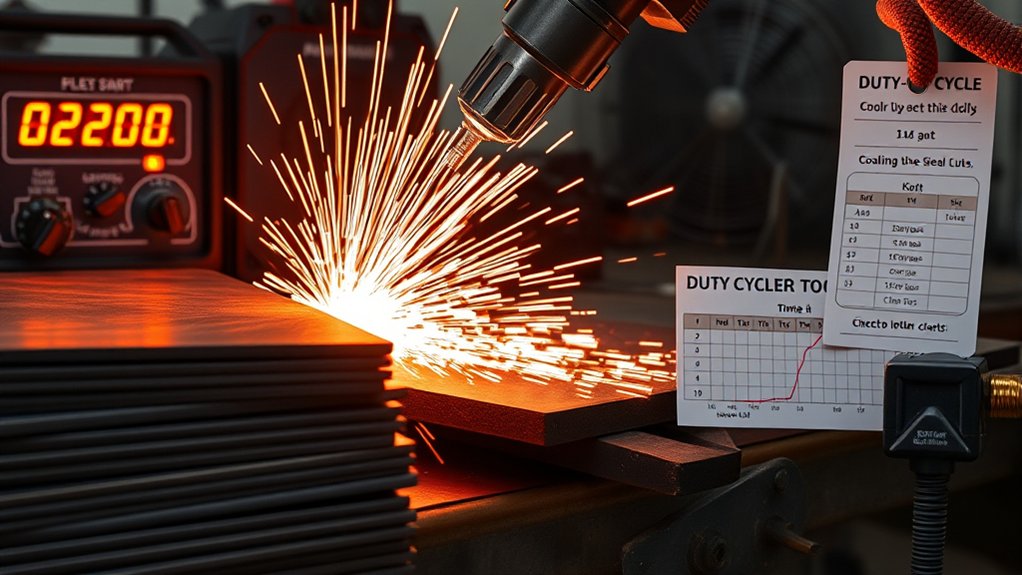
Duty cycle sets how long you can cut before the machine needs cooling time. Many 40 amp units rate duty cycle over a 10 minute period.
A 60% duty cycle means you can cut for 6 minutes and cool for 4 minutes. A 35% duty cycle means you can cut for 3.5 minutes and cool for 6.5 minutes.
Use duty cycle as a hard limit, not a loose guide. Pushing past it can trigger thermal shutdowns and shorten consumable life.
- Calculate cycles: Plan long cuts around the rated arc-on time and cooling time.
- Control the environment: Keep airflow clear and reduce shop heat when possible.
- Match thickness and speed: Stay within the machine’s rated cut capacity to avoid long, slow cuts.
- Track the process: Log arc-on minutes, thermal trips, and fan run time during heavy work.
Note: Duty cycle ratings vary by brand, input power, ambient temperature, and test method.
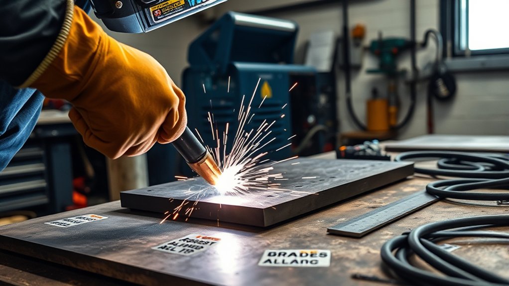
Material-Specific Notes: Mild Steel, Stainless, and Aluminum
Metal type affects cut quality as much as amperage does. A 40 amp plasma cutter may cut mild steel up to about 1/2 in, stainless steel up to about 3/8 in, and aluminum up to about 1/4 in, depending on the machine and cut standard.
For mild steel, run near 40 A on thicker stock, keep air within the machine’s specified range, and use moderate speed to limit dross and taper. Mild steel gives you the widest working window.
Stainless steel needs tighter heat control. Reduce amperage slightly on thin sheet, move faster, and keep torch-to-work distance steady to limit warping.
For aluminum, use fast travel and dry, stable air. FineCut consumables can improve detail on thin stainless and aluminum when your torch supports them.
| Parameter Focus | Alloy-Specific Note |
|---|---|
| Amperage trim | Stainless: drop slightly on thin gauges |
| Air pressure | All alloys: hold within spec to reduce dross |
| Travel speed | Aluminum: faster; mild steel: moderate |
Safety Essentials and Best Practices During Cutting
A 40 amp plasma cutter creates an intense arc, hot sparks, fumes, and sharp edges. Set up your personal protective equipment and workspace before you cut.
Wear heavy-duty gloves, safety glasses with side shields, and a face shield when dross or sparks increase. Use hearing protection when noise levels rise.
Maintain cross-flow ventilation or local exhaust, especially when you cut painted, galvanized, or coated metal. Keep a class ABC fire extinguisher nearby, and clear combustibles from the spark path.
Warning: Do not cut sealed containers, coated metals, or unknown materials without proper hazard checks and ventilation.
- Run pre-checks: Inspect torch leads, the ground clamp, dry flooring, and workpiece support.
- Control the cut: Keep a stable stance and direct sparks away from hoses and cords.
- Manage fumes: Place extraction near the plume and confirm airflow before arcing.
- Handle parts safely: Let parts cool, mark hot metal, and deburr edges before handling.
Frequently Asked Questions
How Do Ambient Temperature and Humidity Affect Plasma Cutting Performance?
Heat and humidity can reduce arc stability and shorten consumable life. Moist air can add water to the plasma stream, which can increase dross and make starts less reliable.
Use a dryer or water separator when your compressor sends damp air to the torch. Cold, dry air often gives you a steadier cut and more repeatable kerf.
What Extension Cord Gauge Is Suitable for a 40-Amp Plasma Cutter?
Use the cord size your plasma cutter manual specifies for your input voltage and distance. A short, heavy-gauge copper cord helps reduce voltage drop and protects cut quality.
For longer runs, step up cord size rather than pushing a small cord past its limit. Use outdoor-rated cords, correct plug types, and ground-fault protection where required.
Can a Generator Reliably Power a 40-Amp Plasma Cutter?
A generator can power a 40 amp plasma cutter when it meets the cutter’s running wattage, surge demand, and power quality needs. Many cutters need a generator in the 9–10 kW class, but the correct size depends on the specific machine.
Check the manual for total harmonic distortion limits and input amperage. Poor generator output can cause weak starts, unstable arcs, and reduced duty cycle.
How Do I Troubleshoot Inconsistent Arc Starts or Frequent Arc Blowouts?
Check the nozzle, electrode, swirl ring, and electrode-to-nozzle fit first. Replace worn consumables, then confirm clean air, correct pressure, and a solid ground clamp.
Keep lead routing clean and shield the cut area from drafts. Confirm steady input power if the arc still drops out.
Which Air Filtration or Dryer Setup Best Protects the Torch and Consumables?
A strong air setup starts with a particulate filter, then a dryer, then a fine coalescing filter near the machine. This setup helps remove dust, water, and oil before they reach the torch.
Drain the compressor tank often and service filters on schedule. Clean air protects consumables and keeps cut quality more consistent.
Final Cutting Tips for Clean, Repeatable Results
Clean cuts come from matched amperage, steady air, the right consumables, and controlled travel speed. Start with the thickness chart, then tune from the sparks, kerf, bevel, and dross.
Record each good setting so you do not have to relearn it on the next job. With a steady process, your 40 amp plasma cutter can produce cleaner edges, less waste, and more repeatable parts.