Plasma Cutter Amperage Guide for Steel Thickness
What’s in This Article
- Why Amperage Matters When Cutting Steel
- How to Read and Use an Amperage Vs Thickness Chart
- Recommended Amp Settings for Common Steel Thicknesses
- How to Balance Cut Speed, Amperage, and Quality
- Nozzle Orifice Size, Kerf Width, and Gas Pressure
- Standoff, Voltage, and Bevel Control
- Pierce Height, Pierce Delay, and Consumable Life
- Safety and Setup Best Practices for Thin to Thick Steel Cuts
- Frequently Asked Questions
- Conclusion
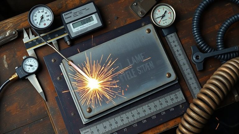
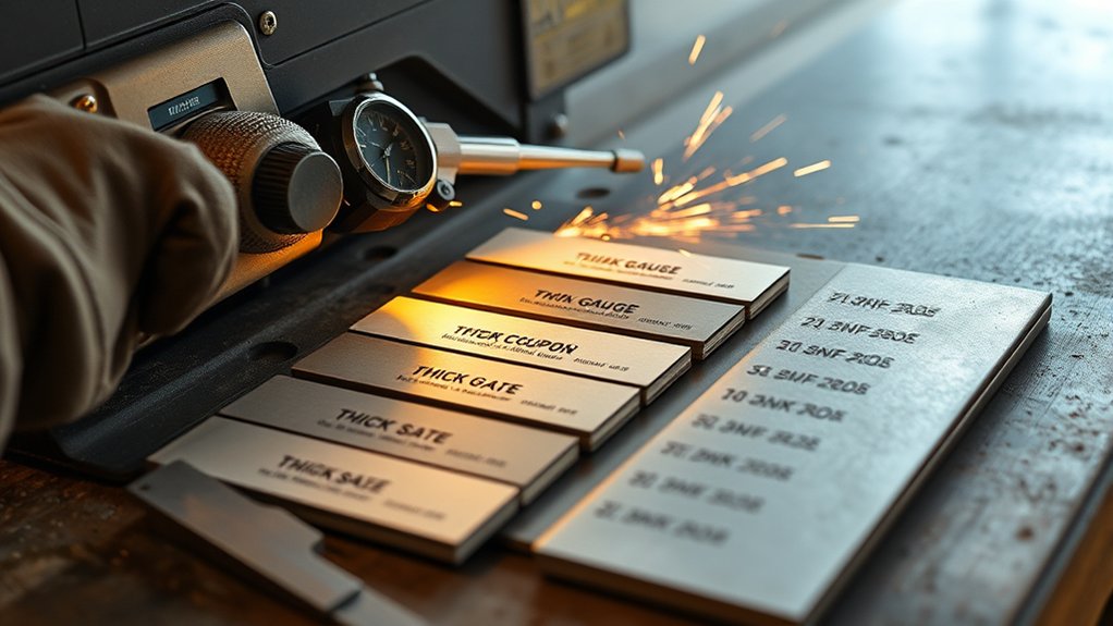
You’ll get consistent cut quality only when amperage, thickness, and travel speed work together. A practical starting point uses about 10 more amps for each more 1/8 in of steel. That means about 20 A for 1/8 in, 40 A for 1/4 in, and 60 A for 1/2 in, with changes for material condition and process gas. This guide shows you how to match amps, speed, standoff, nozzle size, and pierce settings for repeatable results.
Quick Answer
Use about 20 A for 1/8 in mild steel, then add about 10 A for each extra 1/8 in. Treat this as a starting point, not a final setting. Fine-tune amperage with travel speed, standoff, gas pressure, and nozzle size until the cut edge looks clean and square.
Key Takeaways
- Start with about 10 more amps for each extra 1/8 in of mild steel.
- Use your machine chart before production because torch kits and duty cycles vary.
- Balance amperage with travel speed to control dross, bevel, and kerf width.
- Match nozzle size and gas pressure to the amperage rating for a stable arc.
- Set pierce height and delay correctly to protect consumables and improve starts.
Why Amperage Matters When Cutting Steel
Amperage defines cut quality because it sets the arc’s energy, penetration, and travel speed range. You need enough current to cut through the steel thickness without forcing the torch to crawl. You also need control so the plasma jet keeps a stable kerf without excess heat.
A practical baseline uses about 10 more amps for each extra 1/8 inch of steel. For example, 20 amps can suit 1/8 inch mild steel, while 40 amps can suit 1/4 inch mild steel. Use this rule as a setup guide, then confirm the setting with your machine chart.
Higher amperage can improve cutting efficiency because it lets you move faster and reduce bottom dross. Too much amperage can widen the kerf, round the top edge, and distort thin material.
Watch for overmelting, heavy lag lines, and a heat-affected zone that exceeds your tolerance. Use the machine’s maximum rated amperage on thicker steel only when the edge quality and dimensional accuracy remain acceptable.
Adjust for alloy and surface condition. Stainless steel, aluminum, rust, paint, and coatings can shift the best setting because they affect heat flow and arc stability.
Products Worth Considering

Foot pedal for Lotos plasma cutter and welder combos CT520D LTPDC2000D
![ARCCAPTAIN iControl CUT60 Pro Plasma Cutter, [APP Control] 60Amp Pilot Arc 120/240V Plasma Cutter Machine, Cuts 15/16" Max, Supports Rust Removal & Expanded Metal, LED Display, 2T/4T, PA/PT, MCU 3.0](https://m.media-amazon.com/images/I/51S76NEO2JL._SL500_.jpg)
[ENHANCED CUTTING CAPACITY] - Equipped with a 3nd-Gen MCU, this plasma cutter delivers powerful output across both voltage options. On 120V, it supports a cutting range of 10–16 mm when the air pressure is kept above 55 PSI. Switching to 240V unlocks heavier performance, cutting 16–26 mm (up to 15/16" / 24 mm) with the recommended 55–75 PSI air pressure. The arc remains stable on stainless steel, carbon steel, aluminum, and copper, producing smooth edges with minimal slag and reducing follow-up grinding.

Foot Pedal for Plasma Cutter Welder Amp Control 3+2 Pins connection
How to Read and Use an Amperage Vs Thickness Chart
Your chart gives you the safest starting point for current, thickness, and duty cycle. Use it before you rely on a general rule. A chart helps you match the torch, nozzle, air pressure, and plate thickness to the same setup window.
Start with chart interpretation: find the steel type, plate thickness, and your model’s duty cycle limits. Read the recommended current, then confirm the nozzle rating and gas setting. Use the 10-amp-per-1/8-inch rule as a cross-check, not as a replacement for the manufacturer’s table.
Start with chart interpretation: match steel, thickness, duty cycle, current, nozzle, and gas settings.
Make amperage adjustments in small steps while you watch the kerf profile, dross, and travel speed. Increase current if the torch struggles to sever the steel. Reduce current if you see a wide kerf, top-edge wash, or too much heat.
For 3/8 inch steel, many setups land near 50 amps. For 1/2 inch steel, many setups land near 60 amps. Confirm these values against your own model because torch design, air quality, and consumables can change the result.
Record your best settings after each test cut. Those notes help you repeat the same cut later with less trial and error.
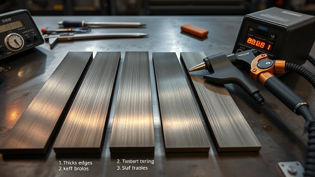
Recommended Amp Settings for Common Steel Thicknesses
Every machine and torch kit has its own limits, but you can set a reliable baseline for mild steel. Match amperage to thickness in 1/8-inch steps. Start at 20 A for 1/8 in, then add about 10 A for each extra 1/8 in.
| Thickness (in) | Recommended Amps |
|---|---|
| 1/8 | 20 |
| 3/16 | 30 |
| 1/4 | 40 |
| 3/8 | 50 |
| 1/2 | 60 |
Use this table as your first setup point before fine-tuning. At 40 A on 1/4 in, many cutters give a stable arc and clean separation. At 50 A on 3/8 in, the extra energy helps reduce lag lines while you keep a steady speed.
At 60 A on 1/2 in, the arc has more energy to reach through the full thickness. Test before production because duty cycle, air flow, ground quality, and consumable wear can change the cut. Validate the setting with scrap material from the same job.
Pro tip: Keep a simple cut log with thickness, amps, air pressure, speed, and edge results.
Products Worth Considering

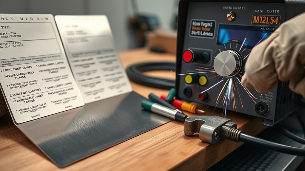
Use the chart in the pictures to find your plasma cutter and drag shield diameter.
Use the chart in the pictures to find your plasma cutter and drag shield diameter.
Packaging: you will receive 3 plasma templates in 9 different sizes: slot lengths of 2, 4, or 6 bolt lengths
How to Balance Cut Speed, Amperage, and Quality
You need to balance amperage and travel speed to control kerf width, edge angle, and dross. Use about 10 more amps per extra 1/8 inch as a starting point. Then adjust speed until the arc exits the bottom of the plate cleanly.
Match current to speed. For manual cuts, use a steady pace that keeps the arc from dragging too far behind the torch. With automation, you can run faster when the arc stays stable and the edge remains square.
If you raise amperage without adding thickness, you may cut faster but risk overmelting and distortion. If you move too slowly, heat builds up and warping increases. Prioritize heat management by changing one setting at a time.
Watch the cut while you move. A trailing arc plume and heavy bottom dross often mean slow travel. Bevel, top spatter, and incomplete separation can point to poor speed, poor standoff, or a setting mismatch.
Nozzle Orifice Size, Kerf Width, and Gas Pressure
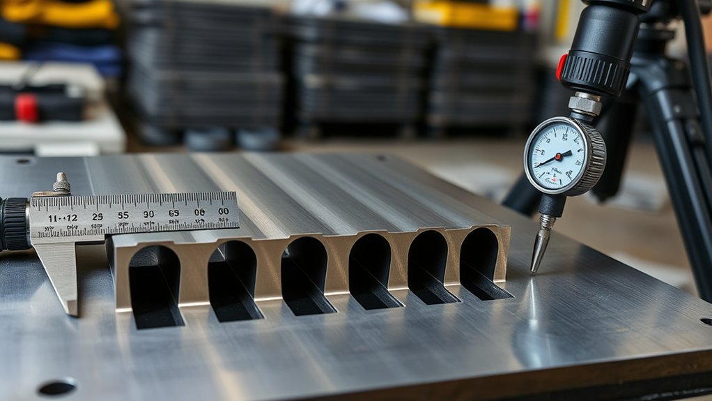
Nozzle geometry controls arc shape and energy density. You need to match orifice size, amperage, and gas pressure to control kerf width and cut quality. Larger orifices widen the arc and kerf, while smaller orifices focus energy into a narrower slot.
Use nozzle adjustments that match the tip rating to your current. For example, a 30 A tip may use a 0.8 mm (0.030 in) orifice at 55-60 psi. Check your torch manual because tip sizes and pressure bands vary by brand.
| Tip/Amperage | Orifice Size | Typical Gas Pressure |
|---|---|---|
| 30 A | 0.8 mm (0.030 in) | 55-60 psi |
| 40 A | About 0.9 mm | 60-65 psi |
| 50 A | About 1.0 mm | 65-70 psi |
| 60 A | About 1.1 mm | 70-75 psi |
| 70-80 A | About 1.2 mm | 75-80 psi |
Kerf width changes with material type and surface condition. Stay within the manufacturer’s pressure range and verify air flow under load. Proper pressure helps prevent arc wander, reduce dross, and extend nozzle life.
Standoff, Voltage, and Bevel Control
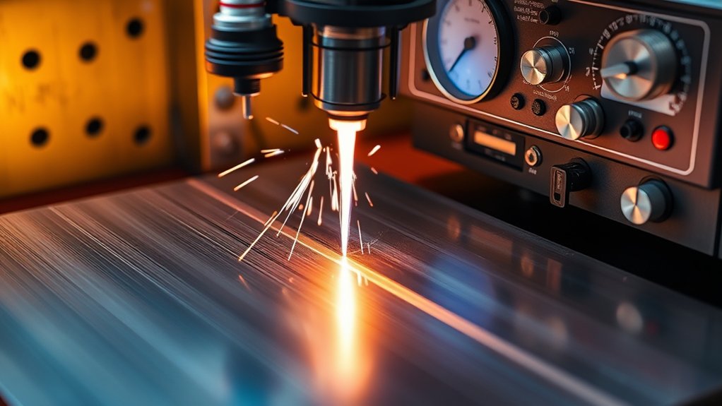
After you set nozzle size, amperage, and gas pressure, control torch standoff and arc voltage. These settings help you keep kerf geometry and bevel within tolerance. Arc voltage rises as torch distance increases, so height changes can change the bevel.
Hold a steady torch-to-work distance to stabilize voltage and reduce heat-related warping. Set voltage for the plate thickness and torch setup. Too little height can create dross and a rough kerf, while too much height can increase bevel and edge heat.
Maintain constant torch height to stabilize voltage and reduce dross, kerf drift, and uneven bevel.
For thicker steel, increase voltage only within the torch maker’s guidance while you keep a fixed operating standoff. Watch for bumps, mill scale, and warped plate. Even small height changes can affect voltage and bevel.
Use height control on computer numerical control (CNC) cutting when your setup supports it. After the pierce, move to cutting height before steady travel. Measure bevel angle and kerf width, then adjust standoff or voltage as needed.
Pierce Height, Pierce Delay, and Consumable Life
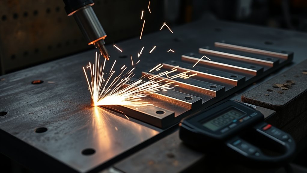
Cutting height controls kerf quality, but pierce height and delay protect consumables. Set pierce height higher than cutting height so molten metal does not splash back into the nozzle. Many setups use a pierce height around 1.5-2.0 times the cutting height.
For thin steel, a short pierce delay lets the molten pit form before motion starts. Thicker plate needs a longer dwell so the arc clears a path before travel begins. Too much delay can widen the start point and round the top edge.
After the pierce, move down to cutting height before X-Y motion. Check arc transfer timing in your CNC setup so the machine does not move too early.
Audit the results by checking divot size, dross at lead-ins, and nozzle orifice wear. If you see crater spatter or tip burn, increase height or delay in small steps. If the lead-in grows too long, reduce delay.
Steady monitoring and adjustment can extend consumable life and lower replacement cost.
Safety and Setup Best Practices for Thin to Thick Steel Cuts
Set pierce height and delay to spec, then prepare the workstation. Good setup keeps the cut controlled and repeatable from thin sheet to heavy plate.
Put on safety equipment before you start. Use heavy-duty gloves, safety glasses, and reinforced boots. Confirm grounding, ventilation, and a clear path for hot parts.
Warning: Avoid cutting coated or galvanized steel without proper ventilation because fumes can create serious health risks.
Suit up with gloves, safety glasses, and reinforced boots. Verify grounding, ventilation, and a clear path for hot parts.
Calibrate amperage to thickness. Use 20 A up to 1/8 in, then add about 10 A for each extra 1/8 in. Document these setpoints on your job traveler or shop note.
Secure the metal for its thickness. Use magnets and low-heat clamps for thin sheet. Use rigid, distributed clamping for plate so the work does not slide or warp during cutting.
Maintain a constant standoff with height control or a gauge. Stable height helps stabilize arc voltage and limit bevel changes from surface irregularities.
Align lead-ins and lead-outs before the cut. Apply kerf compensation so parts do not drop into the kerf. Check the nozzle, shield, and electrode, then replace worn parts before they hurt edge quality.
Run a dry run before you strike the arc.
Common Cut Quality Problems and What They Mean
Cut problems often point to one setup issue. Heavy bottom dross usually means slow travel, low current, poor air flow, or worn consumables. A wide kerf can point to too much current, too much heat, or the wrong nozzle.
Top spatter and bevel can come from poor speed, poor standoff, or incorrect air pressure. Incomplete cuts often mean the amperage, speed, or pierce delay does not match the steel thickness. Change one setting at a time so you know what fixed the issue.
Frequently Asked Questions
How Does Ambient Temperature or Humidity Affect Amperage Selection?
Ambient conditions usually need only small amperage changes. Cold air can cool the cut faster, while heat and humidity can reduce cooling and affect air quality. Prioritize metal thickness, duty cycle, and cut quality, then test on scrap before production.
What Duty Cycle Considerations Impact Long Continuous Cuts?
Duty cycle tells you how long the cutter can run at a rated output before it needs cooling time. Long cuts at high amperage can overheat the machine, trigger shutdowns, and reduce cut quality. Use the rated current, allow pauses when needed, and avoid pushing the machine past its limit.
How Do Generator Power Variations Influence Cut Consistency?
Generator stability affects arc quality because voltage sag can cause weak amperage and an uneven kerf. Use a generator with enough output headroom, clean power, proper grounding, and rated cords. Poor power can cause rough starts, uneven penetration, and more dross.
Are There Differences for Painted, Galvanized, or Rusted Steel Surfaces?
Yes. Paint, zinc coating, and rust can disturb arc stability and change the kerf. Remove paint where practical, de-scale rust, and use strong ventilation when cutting coated material.
How Do CNC Vs Handheld Torches Change Amperage Choices?
CNC torches can often use faster travel because the machine keeps speed and standoff steady. Handheld cutting usually needs more conservative settings because your speed and height vary. Start with the same chart, then adjust after a test cut.
Conclusion
The best plasma cutter amperage setting starts with thickness, but the final cut depends on your full setup. Use about 10 more amps for each extra 1/8 inch of mild steel, then fine-tune speed, standoff, gas pressure, and nozzle size. Set pierce height and delay with care so you protect consumables and get cleaner starts.
Before production, make one test cut on matching scrap and inspect the edge. A few careful adjustments can turn a rough cut into a clean, repeatable result.