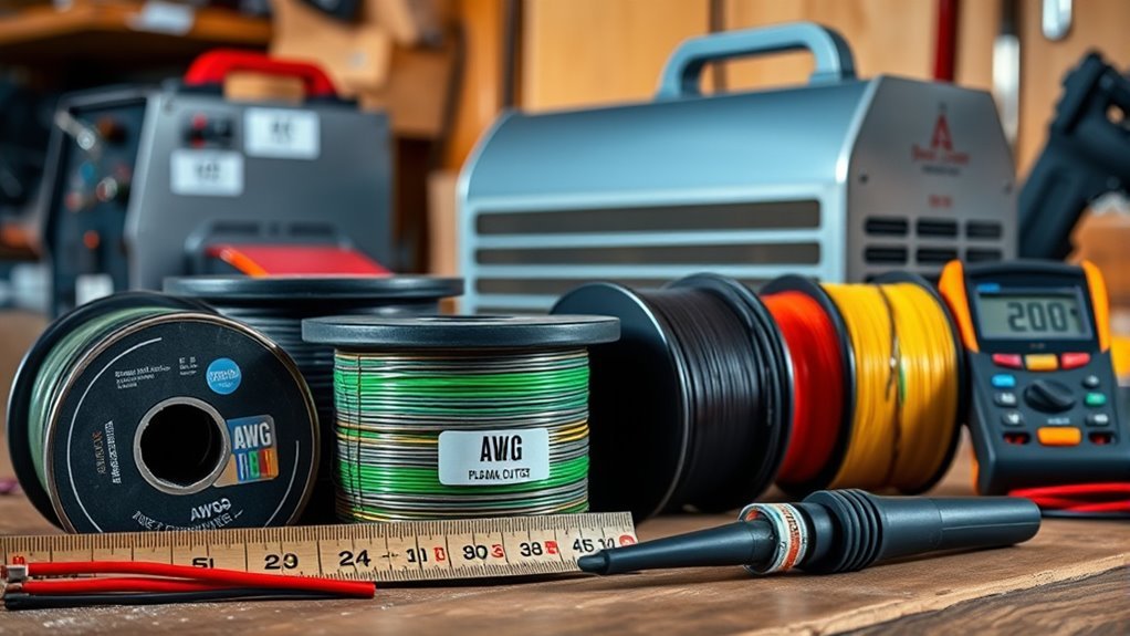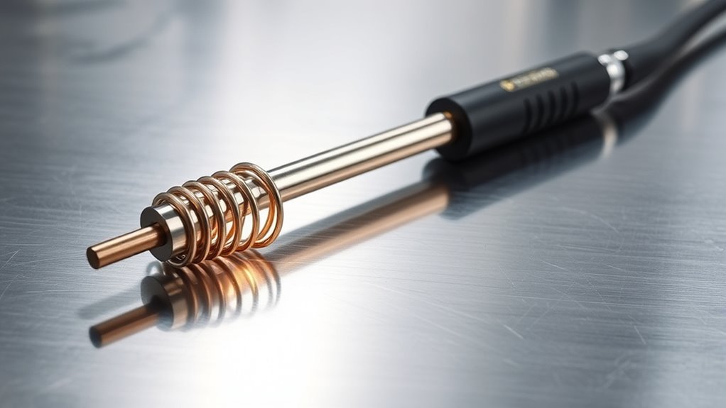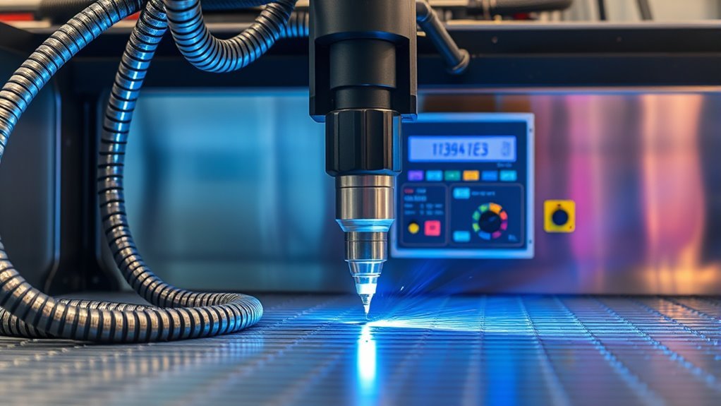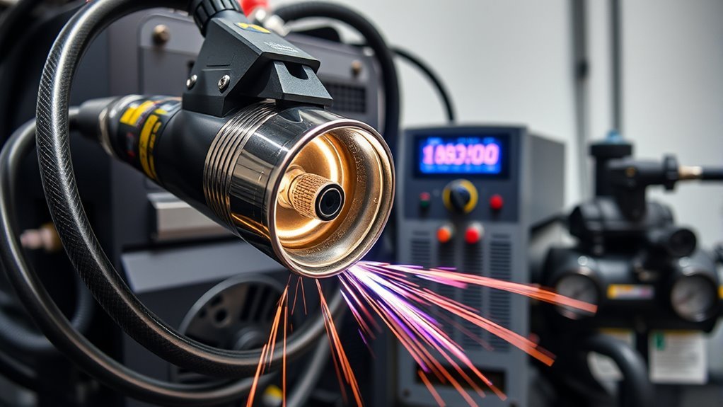
A plasma cutter looks simple from the outside, but clean, repeatable cuts depend on several systems working together. The main plasma cutter parts are the power supply, torch and consumables, gas or compressed-air circuit, work lead, controls, and safety interlocks. Knowing what each part does makes it easier to choose a machine, diagnose poor cuts, and avoid preventable damage.
Quick Answer
A plasma cutter has four core systems: a DC power supply, a torch and its consumables, a gas or compressed-air circuit, and controls with safety interlocks. The power supply creates the arc, the torch constricts it, gas ejects molten metal, and the work lead completes the cutting circuit. Exact pressure, voltage, and wear limits are model-specific.
Key Takeaways
- Plasma cutters work only on electrically conductive materials, including mild steel, stainless steel, aluminum, copper, and brass.
- The torch consumable stack may include a shield, retaining cap, nozzle, electrode, and swirl ring, or a single-piece cartridge on newer systems.
- Air pressure and flow must match the operator manual. A compressor with enough CFM at the required pressure matters more than tank size alone.
- Consumables should be changed according to visible wear, fault codes, cut quality, and manufacturer limits, not a fixed number of hours.
- The work clamp completes the cutting circuit. Protective earth grounding is a separate electrical-safety function.
At a Glance
| Time Required | About 10–15 minutes to identify and inspect the external parts before use |
| Difficulty | Beginner for routine inspection; qualified service personnel for internal electrical repair |
| Tools Needed | Operator manual, proper PPE, clean and dry gas supply, inspection light, and approved replacement parts |
| Cost | No added cost to inspect; filters, consumables, and service costs vary by model and duty cycle |
What Is Plasma and Why It Matters for Cutting?
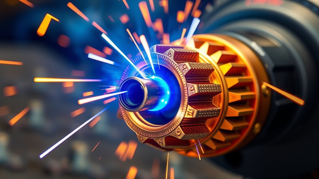
Plasma is an ionized gas that contains electrically charged particles. In a plasma cutter, electrical energy changes a flowing gas into a conductive arc. The torch nozzle constricts that arc into a fast, concentrated jet that melts metal while the gas stream pushes molten material out of the cut.
According to Hypertherm’s plasma technology guide, a plasma arc can approach 40,000°F. That temperature is at the arc, not across the whole workpiece. Travel speed, amperage, torch height, gas choice, and nozzle condition determine how much heat reaches the cut.
Plasma arc cutting requires an electrically conductive workpiece. It can cut mild steel, stainless steel, aluminum, copper, brass, and other conductive alloys. It cannot directly cut wood, glass, masonry, or most plastics.
Gas selection depends on the system and material. Portable air plasma cutters commonly use clean, dry compressed air. Industrial systems may use oxygen, nitrogen, argon-hydrogen, or other process gases to improve speed, edge quality, or metallurgy.
Cut quality is a system result: power, gas flow, torch height, travel speed, consumable condition, and material all affect the finished edge.
Main Parts of a Plasma Cutter
Most handheld plasma cutters contain the same basic systems, although the design and part names vary by brand. Mechanized and CNC systems add motion controls, torch-height control, machine interfaces, and often more complex gas consoles.
| Part or System | Primary Job | Common Signs of Trouble |
|---|---|---|
| Power supply | Converts input power into controlled DC current for the plasma arc | Fault lights, overheating, unstable output, or failure to start |
| Torch and consumables | Creates, constricts, directs, and shields the arc | Wide kerf, bevel, double arcing, excess dross, or misfires |
| Gas or air system | Supplies clean gas at the specified pressure and flow | Pressure faults, moisture, oil contamination, or arc dropout |
| Work lead and clamp | Completes the cutting-current path through the workpiece | Intermittent arc, poor transfer, heat at the clamp, or no cut |
| Controls and interlocks | Manage amperage, gas timing, cooling, faults, and safe operation | Cap, pressure, temperature, trigger, or input-power fault codes |
How a Plasma Cutter Works: Step by Step
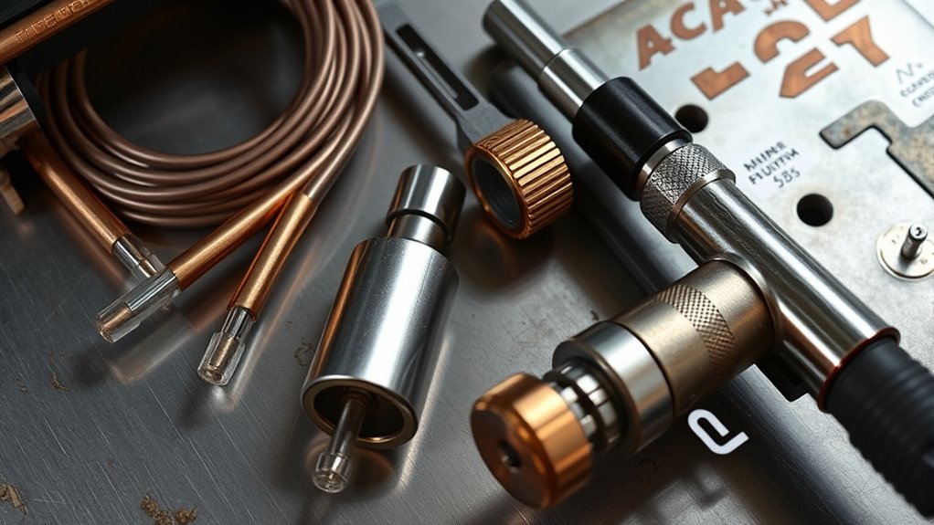
The exact startup sequence varies, but a typical handheld system follows these stages:
- The work lead is connected. Attach the work clamp to clean, bare metal on the workpiece or a cutting table that has a reliable electrical path to it. Do not attach the clamp to the section that will fall away.
- Gas preflow begins. Pulling the trigger starts compressed-air or process-gas flow and confirms that pressure and safety interlocks are satisfied.
- The starting circuit creates a pilot arc. Depending on the system, a high-frequency spark or a moving-electrode, blowback-style mechanism ionizes the gas inside the torch.
- The arc transfers to the workpiece. When the torch is close enough to conductive metal, current transfers from the pilot path to the workpiece and forms the main cutting arc.
- The plasma jet melts and ejects metal. The focused arc melts a narrow path, and the high-speed gas stream blows the molten metal through the kerf.
- Postflow cools the torch. Gas may continue after the trigger is released. Do not interrupt this cooling cycle unless the operator manual directs otherwise.
For a manufacturer walkthrough, see how a plasma cutter works and Hypertherm’s basic plasma-cutting procedure.
Warning: Plasma systems contain hazardous voltage and can cause electric shock, burns, fire, eye injury, hearing damage, and toxic-fume exposure. Keep the machine dry, follow the operator manual, use proper ventilation and PPE, and leave internal electrical service to qualified personnel.
Power Supply and Electrical Components
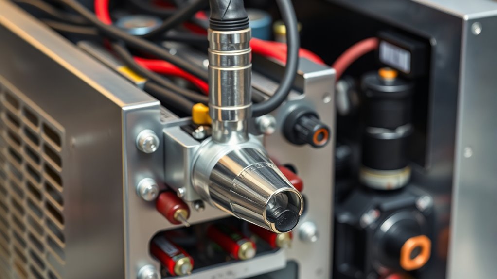
The power supply converts incoming AC power into controlled DC current for cutting. Many portable machines use inverter electronics, while larger industrial systems may use different architectures. Open-circuit voltage, input current, output current, and internal bus voltage vary by model, so a single voltage range does not describe every plasma cutter.
The front panel or digital display may control amperage, operating mode, gas test, torch type, and fault information. Internal control boards manage gas timing, arc transfer, fan operation, thermal protection, and safety interlocks.
Common electrical and control parts include:
- Input rectifier and inverter: condition line power and regulate output.
- Arc-start circuit: initiates ionization using high-frequency voltage or a lower-interference moving-electrode design.
- Current sensor and control board: hold output near the selected amperage.
- Cooling fan and thermal sensors: limit overheating and enforce the rated duty cycle.
- Pressure and parts-in-place switches: prevent firing when gas flow or torch assembly is unsafe.
- Protective earth connection: connects the chassis to the electrical grounding system for shock protection.
Note: The work clamp is not a substitute for protective earth grounding. It carries cutting current through the workpiece, while the equipment grounding conductor protects the machine chassis and operator during an electrical fault.
Plasma Torch: Electrode, Nozzle, Swirl Ring, Shield, and Cap
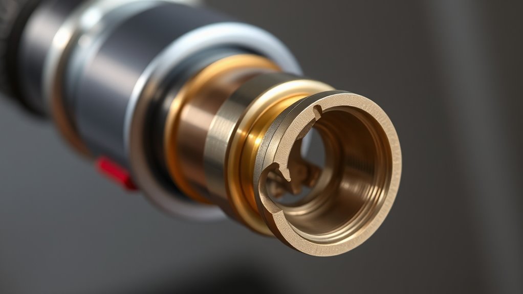
The torch holds and aligns the parts that create and shape the plasma arc. Traditional torches use several separate consumables. Some newer systems use a one-piece cartridge that combines multiple functions.
| Torch Part | What It Does | What to Inspect |
|---|---|---|
| Electrode | Carries current and supports the arc at an emitter in its tip | Pit depth, uneven erosion, overheating, or cracking |
| Nozzle | Constrains and directs the plasma arc through a precise orifice | An enlarged, notched, oval, or damaged opening |
| Swirl ring or gas baffle | Controls gas rotation and centers the arc | Blocked holes, cracks, burns, or incorrect orientation |
| Retaining cap | Holds consumables in position and may engage a cap-sensing interlock | Cracks, damaged threads, burns, or loose fit |
| Shield or drag cap | Protects the nozzle and sets or supports standoff on compatible torches | Blocked vents, spatter buildup, cracks, or impact damage |
Consumable order, torque, compatibility, and wear limits are torch-specific. Install only the parts listed in the operator manual. A nozzle designed for one amperage or process may produce poor cuts or fail early when used at another setting.
Pilot Arc, High-Frequency Start, and Blowback Start
“Pilot arc” and “contact start” are often used as shopping terms, but they do not fully describe the starting circuit. A pilot arc is a small arc inside or near the torch that prepares a conductive path before the main arc transfers to the workpiece. The machine can create that pilot arc in more than one way.
High-Frequency Start
A high-frequency system uses a high-voltage, high-frequency spark to ionize the gas. It can start without touching the workpiece, but it may create electromagnetic interference. This matters near CNC controls, computers, radios, and other sensitive electronics.
Blowback or Moving-Electrode Start
A blowback-start torch briefly moves an internal electrode relative to the nozzle as gas begins to flow. That movement creates the initial arc without the same level of high-frequency electrical noise. Many modern portable and light-industrial machines use this design.
Touch or Scratch Starting
Some basic systems require the torch tip to contact or closely approach the workpiece during startup. These machines can be less convenient on painted, rusty, perforated, or uneven material. Do not assume that every machine sold as “pilot arc” uses the same start technology; check the manual and electrical-noise guidance.
Pro Tip: For a CNC plasma table, look for a system specifically approved for mechanized use and low-interference starting. Also follow the table and plasma manufacturers’ grounding, shielding, cable-routing, and interface instructions.
Gas and Air Systems: Compressors, Filters, and Regulators
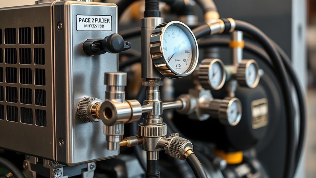
Portable air plasma cutters need enough clean, dry, oil-free air at the pressure and flow stated in the manual. Do not use a generic 70–120 psi rule. Different machines require different inlet ranges and dynamic flow rates, and too much pressure can be as harmful as too little.
When sizing a compressor, compare the cutter’s required CFM at the specified pressure with the compressor’s continuous output. Tank size affects how long the compressor can coast, but it does not replace adequate pump capacity. Leave reserve capacity for pressure loss, filters, hoses, altitude, heat, and compressor duty cycle.
The air path may include:
- Compressor or cylinder: supplies the required gas volume.
- Particulate filter: removes rust, scale, and solid debris.
- Coalescing filter: captures fine oil and water aerosols.
- Dryer: reduces water vapor in humid shops or long air lines.
- Regulator and pressure sensor: hold pressure within the machine’s operating range.
- Drain and separator: remove condensed water from the tank and piping.
Moisture and oil shorten parts life, damage the torch, and reduce cut quality. Hypertherm’s guide to plasma-cutter air quality explains why contamination can affect both consumables and the power supply.
Note: Check pressure while gas is flowing, not only while the machine is idle. Static pressure can look acceptable even when restricted fittings, long hoses, or undersized filters cause a large drop under load.
Products Worth Considering

【Product Name】1/4" NPT Air Pressure Filter/Regulator Unit

【Industrial Performance】The air drying system features two rugged 3/4“ NPT air ports and 1/4” NPT gauge ports to handle high-pressure environments (up to 240 PSI) for a variety of industrial applications. Note: To prevent air leakage, please wrap the sealing tape around the threads appropriately before connecting the screws.

3/8" NPT Piggyback Air Filter/Regulator Combo
Work Lead, Controls, and Safety Interlocks
The work lead connects the positive or negative side of the cutting circuit, depending on system design, to the workpiece. The clamp needs clean metal-to-metal contact. Paint, rust, mill scale, loose jaws, damaged cable, or a connection on the drop piece can interrupt arc transfer.
Safety and control features vary, but common examples include a guarded trigger, torch-disable switch, cap sensor, gas-pressure switch, over-temperature protection, input-voltage monitoring, and postflow timing. Mechanized systems may also include an emergency stop, breakaway torch mount, machine-motion interlocks, CNC interface, and torch-height controller.
Never bypass an interlock to make the torch fire. A cap or pressure fault may be preventing exposed live parts, torch damage, or an unstable arc.
Consumables, Wear Parts, and Maintenance Tips
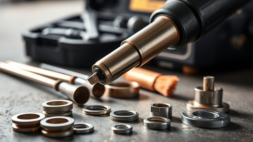
Consumable life cannot be reduced to a universal “one to two hours” rule. It changes with amperage, number of starts, pierce technique, torch height, air quality, material, part quality, cooling, and operator technique. Some parts fail early from contamination or double arcing, while properly operated systems may deliver hundreds or more than a thousand starts in suitable applications.
Inspect parts regularly and use the limits in the torch manual. Common replacement signs include:
- an electrode pit that reaches the manufacturer’s wear limit;
- a nozzle opening that is oval, enlarged, notched, or burned;
- a cracked or blocked swirl ring;
- a damaged retaining cap or shield;
- repeated misfires, arc wandering, wider kerf, excess bevel, or sudden dross;
- fault codes that remain after correct assembly and pressure checks.
Do not discard parts solely because a set number of hours has passed. Hypertherm’s guides on extending consumable life and common plasma-cutting mistakes recommend judging parts by wear and using the correct consumables and settings.
Practical Maintenance Schedule
| Interval | Checks |
|---|---|
| Before each use | Inspect torch parts, work clamp, leads, hoses, fittings, PPE, and the work area; drain visible moisture as directed. |
| During cutting | Watch pressure, arc behavior, travel speed, postflow, cut angle, and dross. |
| At the manual’s interval | Service filters, fan passages, coolant systems, regulators, and internal components as specified. |
| When performance changes | Stop and inspect consumables, air quality, pressure under flow, work-clamp contact, and machine fault codes. |
Sizing, Capabilities, and Matching a Cutter to Your Work
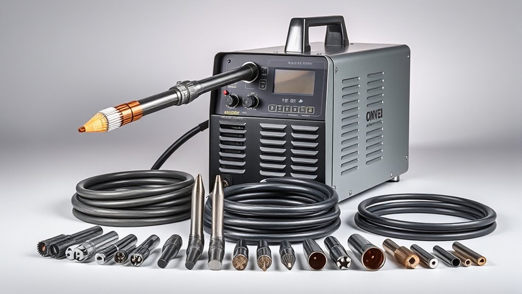
Amperage matters, but it is only one part of sizing a plasma cutter. Compare manufacturer cut charts and ratings for your exact material, thickness, power supply, torch, gas, and desired cut quality.
Products Worth Considering
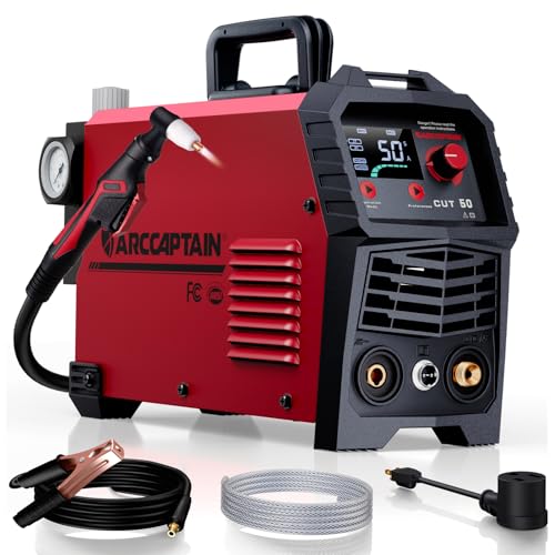
【Powerful Cutting Ability】Switch effortlessly between 110V and 220V for home or workshop use. Achieve professional 1/2" clean cuts on steel, aluminum, and copper with advanced LGBT technology. Perfect for DIY projects and heavy-duty tasks. Recommended maximum cutting thickness: 12mm @ 35A / 110V / 55 PSl; 18mm @ 50A / 220V / 75 PSI. Note: Requires compressed air (compressor sold separately).

Powerful Cutting: This VEVOR plasma cutter delivers a maximum output current of 65A for powerful cutting. It supports clean cuts up to 1/2" (12mm) at 110V and 9/16" (14mm) at 220V, with a maximum cutting thickness of 5/8" (16mm) at 110V and 3/4" (20mm) at 220V

POWERFUL CUTTING THICKNESS: This plasma cutter handles 1/2" (12mm) steel at 120V/35A and 5/8" (16mm) at 240V/60A. Dual voltage auto-detection (10-35A@120V / 30-60A@240V) with PSI guidance (70-75 PSI / 0.48-0.52MPa). Optimized for quick, efficient cuts in automotive repairs and metal fabrication
Recommended Cut, Maximum Cut, and Severance
Manufacturers may publish several thickness figures. A recommended or quality-cut rating is the most useful for routine work. A maximum rating usually means slower cutting and more cleanup. A severance rating means the machine can separate the material under limited conditions, not that it will produce a production-quality edge.
Input Power and Circuit Requirements
Confirm input voltage, phase, plug type, breaker or fuse size, extension-cord limits, and generator requirements. A dual-voltage machine may deliver less output on 120V than on 240V. Have branch circuits installed or evaluated by a qualified electrician where required.
Duty Cycle
Duty cycle tells you how long the machine can cut at a stated output and ambient temperature before it must cool. Compare duty-cycle ratings at the amperage you will actually use. Production work needs more thermal capacity than occasional repair or hobby cutting.
Air Demand
Verify required CFM and pressure under flow. Built-in compressors improve portability but may limit cut capacity or continuous operation. External compressors should have enough reserve to avoid pressure faults during long cuts.
Torch and Process Options
Check whether the system supports drag cutting, standoff cutting, gouging, fine-detail consumables, extended-reach parts, machine torches, and CNC interfaces. Also compare torch-lead length, replacement-part availability, consumable cost, service support, and warranty terms.
Pro Tip: Buy for the thickness you cut most often, not the thickest piece you might sever once. A machine operating near its maximum on every job will usually cut more slowly and spend more time near its duty-cycle limit.
Common Plasma Cutter Problems and What to Check
| Symptom | Likely Checks |
|---|---|
| Torch will not fire | Torch lock, trigger, cap installation, gas pressure, input power, fault code, and correct consumables |
| Pilot arc starts but will not transfer | Work-clamp contact, paint or rust, standoff distance, damaged work lead, and conductive material |
| Excess dross | Travel speed, amperage, torch height, worn nozzle, air quality, and material condition |
| Large bevel or wide kerf | Worn or damaged nozzle, incorrect direction, excessive standoff, torch angle, and speed |
| Arc stops during a cut | Duty-cycle limit, pressure drop, compressor output, work-lead connection, input voltage, or consumable fault |
Use the model’s fault-code chart before replacing parts. If troubleshooting requires removing the machine cover, testing energized circuits, or bypassing safety devices, stop and use an authorized or qualified service technician.
Plasma Cutting Safety Basics
Plasma cutting combines electrical, optical, fire, noise, compressed-gas, and fume hazards. Workplace requirements depend on the task, material, amperage, ventilation, exposure assessment, and applicable regulations. A generic PPE list cannot replace a site-specific hazard assessment.
- Eye and face protection: use an appropriate filter shade and impact-rated protection. OSHA lists minimum shades for plasma arc cutting when the arc is visible.
- Skin and hand protection: wear flame-resistant clothing and gloves suitable for hot work and flying sparks.
- Ventilation: capture fumes at the source when practical. Coatings, galvanized metal, stainless steel, and unknown residues can create hazardous contaminants.
- Hearing protection: evaluate noise exposure, especially during high-amperage cutting or gouging.
- Fire prevention: remove combustibles, control sparks and hot drops, and follow the site’s hot-work procedures.
- Electrical safety: keep gloves, equipment, and the work area dry; inspect cables; and disconnect input power before service.
- Containers and pressurized parts: never cut a closed or pressurized container or one that held combustible material unless an approved procedure has made it safe.
See OSHA’s eye and face protection requirements and Hypertherm’s plasma safety and compliance manual for detailed hazard information.
Frequently Asked Questions
Can a plasma cutter be used underwater or in wet conditions?
Do not use a standard handheld plasma cutter in rain, standing water, or other wet conditions. Specialized mechanized systems can cut over or below a water table when the equipment and procedure are designed for it. Aluminum can generate explosive hydrogen around water, so underwater or water-table cutting requires manufacturer-approved controls and a documented risk assessment.
What safety equipment is legally required for plasma cutting in workshops?
Requirements depend on the workplace, exposure, and applicable rules. Employers generally need a hazard assessment and must provide suitable eye and face protection, protective clothing, ventilation or respiratory controls where needed, hearing protection when exposure requires it, and fire-prevention measures. OSHA lists minimum filter shades for visible plasma arcs, but the operator manual and site assessment may call for additional protection.
How do plasma cutters affect nearby electronics or sensitive equipment?
High-frequency starting circuits can create electromagnetic interference that affects CNC controls, computers, communication equipment, and other electronics. Use a low-interference system where appropriate and follow the manufacturers’ instructions for grounding, shielding, cable separation, ferrites, and interface wiring. People with implanted or body-worn medical devices should follow the device maker’s and plasma-system maker’s safety guidance.
Can hobbyists build a DIY plasma cutter safely and legally?
Building a plasma power supply involves lethal voltage, high-energy switching electronics, compressed gas, arc radiation, and fire hazards. It is not a suitable beginner electrical project. Legal and code requirements vary by location and workplace, and a homemade unit may lack tested insulation, interlocks, electromagnetic compatibility, and product certification. Buying a listed machine and leaving internal repair to qualified personnel is the safer choice.
What are typical warranty terms and service options for plasma cutters?
Warranty terms vary by brand and component. Power supplies may receive longer coverage than torches, leads, compressors, or accessories. For example, Hypertherm’s current warranty states six years or 500,000 starts, whichever comes first, for eligible Powermax power supplies, while torch and lead coverage is shorter. Review exclusions for poor input power, unauthorized modification, consumables, commercial use, and transferability before buying.
Can a plasma cutter cut rusty or painted metal?
Many pilot-arc systems can cut through light rust or coatings, but the work clamp still needs a clean electrical connection. Paint, plating, galvanizing, and unknown residues can produce hazardous fumes, so remove coatings where practical and use ventilation and exposure controls suited to the material.
Why does a plasma cutter leave dross on the bottom edge?
Dross often points to travel speed that is too fast or too slow, incorrect torch height, wrong amperage, poor air quality, or worn consumables. Start with the manufacturer’s cut chart, verify pressure while flowing, inspect the nozzle and electrode, and make one adjustment at a time.
Conclusion
The main plasma cutter parts work as one system. The power supply provides controlled DC current, the torch and consumables shape the arc, the air or gas circuit cools the torch and removes molten metal, and the work lead completes the cutting path. Controls and interlocks keep those functions within safe operating limits.
For reliable results, use the exact cut chart, pressure, flow, consumables, and maintenance limits for your model. Inspect parts by condition, keep the air clean and dry, maintain a solid work-clamp connection, and stop when a fault or safety interlock indicates a problem. Those habits improve cut quality, extend component life, and reduce avoidable downtime.
Sources
- Hypertherm: What Is a Plasma Cutter? — plasma temperature, conductive materials, gases, and handheld versus mechanized systems
- Hypertherm: How to Plasma Cut — work-clamp placement and basic operating sequence
- Hypertherm: Plasma Cutter Air Quality — effects of moisture and contamination on cut quality and component life
- Hypertherm: 10 Common Plasma Cutting Mistakes — consumable selection, wear inspection, and operating errors
- Hypertherm Safety and Compliance Manual — electrical, fume, fire, compressed-gas, and underwater-cutting hazards
- OSHA 29 CFR 1910.133 — workplace eye and face protection and plasma arc filter-shade guidance