
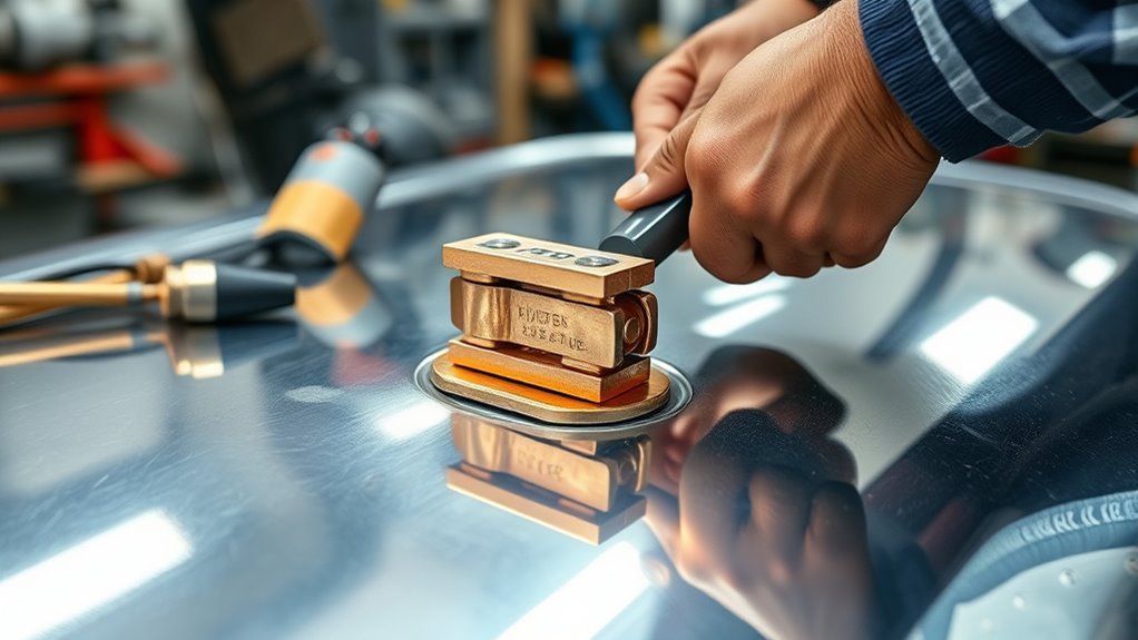
A poor welding return connection can make the arc sputter, heat the clamp, increase spatter, and send current through parts that were never meant to carry it. On a car, the safest setup is a clean, tight work-clamp connection on the same metal section you’re welding, placed as close to the repair as practical, with the vehicle prepared exactly as its manufacturer requires.
Quick Answer
Attach the welder’s work clamp to clean, bare metal on the part being welded, as close to the joint as practical. Remove paint, rust, seam sealer, grease, and undercoating, then make sure the clamp grips firmly. Follow the vehicle maker’s battery, module, air-bag, hybrid, or EV shutdown procedure before striking an arc.
Key Takeaways
- The “ground clamp” is more accurately called the work clamp; it completes the welding circuit and is not the same as the vehicle’s battery ground or the building’s safety earth.
- Clamp to bright, bare metal on the same panel, bracket, frame section, or repair piece whenever possible.
- Keep the return path short and away from wheel bearings, hinges, cables, wiring, fuel lines, brake lines, and electronic modules.
- Do not assume disconnecting one battery cable protects every vehicle. Use the exact OEM service or body-repair procedure.
- Stop if the clamp arcs, gets unusually hot, slips, or the welding arc becomes unstable.
At a Glance
| Time Required | About 10–20 minutes for inspection, surface preparation, clamp placement, and a pre-weld check; longer when trim, coatings, wiring, or modules must be removed or protected. |
| Difficulty | Basic clamp setup; advanced vehicle preparation on late-model, hybrid, EV, air-bag-equipped, or structural repairs. |
| Tools Needed | Welder with undamaged work lead and clamp, wire brush or grinder, clean rag, suitable PPE, fire extinguisher, and an optional multimeter for power-off checks. |
| Cost | No added cost when you already have the required tools; otherwise the cost varies by clamp, abrasives, PPE, and test equipment. |
What’s in This Article
- Work Clamp vs. Ground: Know the Difference
- Essential Tools and Materials
- Why Clamp Placement Matters
- Before You Begin
- Step-by-Step Work-Clamp Setup
- Testing the Connection
- Common Mistakes and Fixes
- Preventing Vehicle Damage
- Hybrid and EV Precautions
- Vehicle Electrical Grounds
- Troubleshooting Symptoms
- Frequently Asked Questions
Work Clamp vs. Ground: Know the Difference
Welders commonly say “ground clamp,” but work clamp is the clearer term. The clamp and work lead complete the welding circuit between the power source and the metal being welded. They are separate from the vehicle’s normal battery-negative grounds and from the protective earth connection used by the welding machine.
This distinction matters because the work clamp should connect to the workpiece, not to a battery terminal, a factory ground stud, a fuel or brake line, or any convenient metal object elsewhere in the shop. The goal is to give welding current a direct route through the repair area and back to the welder.
Note: The work lead is not always negative. Polarity depends on the welding process, wire, and electrode. Solid-wire MIG on mild steel commonly uses DCEP, which normally places the work lead on negative, but you should follow the labels inside the welder and the filler-metal manufacturer’s instructions.
Essential Tools and Materials for Effective Grounding
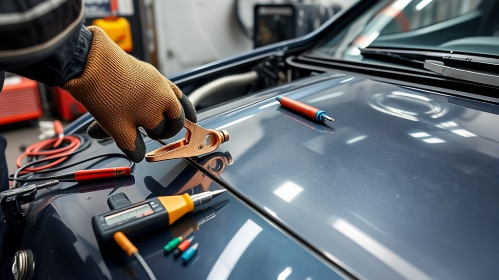
Gather the right tools before you start. You need a sound work lead and clamp, a way to expose clean metal, and enough protective equipment to control sparks, heat, and fumes. A multimeter can help with limited power-off checks, but it does not replace proper clamp preparation or an OEM vehicle procedure.
- Work clamp and cable: The clamp must match the welder’s output, close firmly, and have clean contact surfaces. Replace cracked insulation, loose cable lugs, burned jaws, or weak springs.
- Wire brush, flap disc, or grinder: Use it to remove paint, rust, mill scale, seam sealer, undercoating, and dirt from the clamp spot.
- Clean rag and approved cleaner: Remove loose dust and residue. Let flammable cleaner evaporate fully before welding.
- Multimeter: Use it only on a de-energized circuit for continuity or resistance checks when needed.
- Corrosion-resistant hardware: Use suitable bolts, washers, and terminals only when an OEM-approved permanent vehicle ground point is being repaired or added.
- PPE and fire protection: Wear a welding helmet, safety glasses, flame-resistant clothing, gloves, and suitable respiratory protection when required. Keep an appropriate fire extinguisher close.
Dielectric grease can protect a finished permanent vehicle electrical ground from moisture after the metal-to-metal connection is tightened. Do not put grease, paint, primer, or anti-seize between the welding work clamp and the bare metal because those materials can reduce contact.
If you also use a plasma cutter, follow the same short-return-path principle and review the site’s plasma cutter safety and grounding checklist.
Products Worth Considering

Amp & Cable Capacity: Rated 300A and fits welding cables up to 1/0 AWG, providing a secure, stable connection between the welder and workpiece for reliable grounding.

300A/500A/800A Earth Ground Cable Clip Clamp Manual Welder Electrode Holder Welding Processing Ground Clamp

7 inch long with 1-3/4 inch jaw opening.
Why Proper Grounding Matters in Welding
A sound work-clamp connection reduces resistance in the welding circuit and helps the machine maintain a stable arc. Miller’s setup guidance tells welders to connect the clamp to clean metal because electrical impedance at the work connection can affect performance. Miller’s MIG welding setup guide also emphasizes clean base metal and correct polarity.
Arc Stability and Clamp Heating
Paint, corrosion, a weak clamp spring, a small contact patch, or a loose cable lug can restrict current. Common signs include hard arc starts, an arc that cuts in and out, excess spatter, reduced output, sparking at the clamp, or a clamp that becomes hot quickly.
A good connection does not correct wrong voltage, wire speed, polarity, shielding gas, joint fit-up, or contaminated weld metal. It simply removes one major source of arc trouble. Good setup also supports better control when you follow the proper fillet weld size for the material thickness.
Controlling the Welding-Current Path
Welding current follows every available conductive path, with more current flowing through lower-resistance routes. When the work clamp is far from the weld, current may cross seams, hinges, bearings, cables, or bolted joints before returning to the machine.
That can pit bearing surfaces or create arcing at poor joints. Hendrickson specifically warns that placing a wheel bearing between the work-lead connection and the weld area can damage the bearing by electric arcing. Hendrickson’s welding procedures illustrate why the clamp belongs on the same side of a bearing or rotating joint as the weld.
The best work-clamp location is clean bare metal on the same component being welded, with no bearing, hinge, cable, or questionable joint between the clamp and the arc.
Before You Begin
Plan the repair before you clean a clamp spot. Look on both sides of the panel for fuel lines, vapor lines, brake lines, wiring harnesses, batteries, electronic modules, air-bag components, carpet, sound deadener, seam sealer, glass, and undercoating.
Warning: Do not weld on or near a fuel tank, fuel or vapor line, high-voltage battery, air-bag component, pressurized system, or unknown structural material until the correct manufacturer procedure makes the job safe. Some vehicle structures must not be welded at all.
Read the vehicle-specific service or body-repair information before disconnecting power. There is no universal battery rule for every car. Ford’s body-builder guidance, for example, recommends disconnecting the 12-volt negative cable and the connectors leading to sensitive modules before arc welding or plasma cutting, and it states that disconnecting the battery cable alone is not enough to guarantee module protection. Ford’s 2025 Body Builders Layout Book also calls for a robust welding return connection near the welding area.
Follow the OEM sequence, including ignition-off steps, memory-saving restrictions, required wait times, connector handling, and reconnection checks. Do not use a generic “disconnect the battery and weld” shortcut on a late-model vehicle.
Step-by-Step Guide to Establishing a Ground Connection
Use this sequence after confirming that the repair itself is allowed and the vehicle has been prepared according to the manufacturer’s instructions.
Products Worth Considering

Premium Material: This welded grounding clamp is made of iron. Iron has high strength and hardness and is able to withstand high mechanical stress. Iron grounding clamps ensure stable current transmission and maintain their structural integrity and stability. Iron has good durability, which allows the welding earth clamp to maintain its good performance and appearance during use.

Tweco Style Ground Clamp

SCREW-TYPE LOCK – NO SLIPPING. Forget stiff springs that pop off. Hitbox screw-type handle locks with a simple twist, delivering steady, adjustable pressure that won't loosen under vibration. Zero hand fatigue. Twist, lock, Ground!
1. Choose the Shortest Safe Return Path
- Clamp to the part being welded: Use the repair panel, bracket, frame section, or attached reinforcement whenever the clamp can grip it safely.
- Stay close to the joint: Put the clamp as near to the weld as practical without exposing the clamp or cable to direct heat, spatter, or torch movement.
- Keep sensitive parts out of the path: Do not place wheel bearings, universal joints, hinges, steering joints, control cables, braided straps, wiring, or electronic modules between the clamp and the weld.
- Avoid unreliable shortcuts: Do not rely on a lift, jack stand, suspension spring, exhaust system, trailer hitch ball, body hinge, or shop table to complete the vehicle’s welding circuit.
2. Prepare the Surface to Bright Metal
Remove paint, rust, e-coat, grease, seam sealer, undercoating, and dirt until the clamp can touch bright metal over a useful contact area. Clean both jaws if the clamp grips an edge or flange.
Use a wire brush for light contamination and a flap disc or grinder for heavy coatings. Avoid thinning structural metal or grinding through galvanized coating beyond the area required by the repair procedure. Wipe away debris and let any approved cleaner evaporate before welding.
3. Attach and Inspect the Work Clamp
- Open the jaws fully: Seat the clamp so both jaws make solid contact rather than touching only at one tooth.
- Check the grip: Pull lightly on the cable. The clamp should not twist, slide, or spring off.
- Inspect the cable connection: Make sure the work lead is tight at the welder and at the clamp, with no exposed strands or overheated lug.
- Route the cable safely: Keep it away from sharp sheet-metal edges, moving parts, hot exhaust, pooled liquids, and the weld puddle.
- Confirm polarity: Match the machine and filler-metal instructions. Do not assume the work lead always belongs on negative.
4. Make a Controlled Test Tack
After all safety checks are complete, make a short tack in the approved weld area. Watch and listen for a clean arc start. Stop immediately if the clamp sparks, the cable jumps, the arc cuts out, or the clamp begins heating rapidly.
Pro Tip: When a normal clamp cannot grip the repair safely, use a purpose-built magnetic work clamp or a clean temporary bolted tab at an approved location. Do not create a tack-welded clamp tab unless you already have a safe return path for that first tack.
Testing Your Ground Connection for Reliability
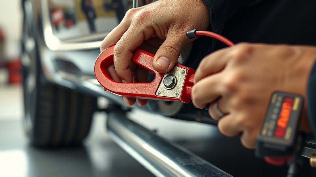
Start with a visual and mechanical inspection. Most bad work connections are easier and safer to find by checking the clamp, jaws, cable, lugs, and prepared metal than by probing a live welding circuit.
- Inspect the contact patch: Confirm that the jaws touch bare metal rather than paint, rust, sealer, or a loose bracket.
- Check the clamp and cable: Look for weak spring pressure, embedded spatter, cracked insulation, loose lugs, broken strands, or discoloration from heat.
- Use continuity only with power off: De-energize the circuit and follow the meter instructions. A continuity beep proves that some conductive path exists, but it does not prove that the path can carry welding current without excessive resistance.
- Compare resistance carefully: Touch the test probes together first so you know the resistance of the leads. A basic handheld meter may not resolve the very small resistance differences that matter in a high-current welding circuit.
- Observe the first tack: A stable arc and a cool, non-arcing clamp are practical confirmation. Recheck the setup if the arc becomes erratic.
Do not perform a live voltage-drop test across a welding circuit unless the welder manufacturer provides a procedure and you are trained to make the measurement safely. The original “0.5-volt” cutoff is not a universal welding specification and should not be used as a generic pass-or-fail rule.
Before you strike an arc, clear the area of flammable materials and hidden spark hazards.
Top Grounding Mistakes and How to Avoid Them
| Mistake | What Can Happen | Better Setup |
|---|---|---|
| Clamping over paint, rust, or undercoating | Hard starts, arcing at the jaws, heat, and unstable output | Expose a broad patch of bright metal and clean the clamp jaws |
| Clamping far from the repair | Current travels through seams, joints, bearings, or wiring paths | Move the clamp to the same component and close to the weld |
| Using the battery negative post or a factory ground stud | Welding current may enter vehicle wiring and electronic ground networks | Connect the work clamp directly to the repair metal |
| Routing current through a wheel bearing or hinge | Electrical arcing can pit contact surfaces | Place the clamp on the same side of the moving joint as the weld |
| Assuming battery disconnection is the only electronic precaution | Sensitive modules can remain connected to harmful current paths | Follow OEM instructions for batteries, module connectors, and wiring protection |
| Using the wrong polarity | Poor penetration, excess spatter, unstable transfer, or damaged consumables | Match the process, wire, electrode, and machine diagram |
If you use stick welding on automotive metal, clamp placement and machine setup both matter. Review the site’s stick welding amperage guidance before choosing an electrode and output setting.
Preventing Damage While Welding
Proper clamp placement is only one part of a safe vehicle-welding setup. You also have to control heat, sparks, fumes, and access to the hidden side of the repair.
- Follow OEM depowering instructions: Disconnect batteries, modules, or high-voltage systems only in the order the vehicle maker specifies.
- Remove or shield nearby wiring: Ford recommends removing wiring from areas of heavy rework or welding when practical, or shielding it from welding heat when removal is not practical.
- Protect fuel and brake components: Do not let the work clamp, welding cable, heat, or spatter contact fuel lines, vapor lines, brake hoses, or brake pipes.
- Check both sides of the panel: Sparks can ignite carpet, foam, seam sealer, insulation, or undercoating on the hidden side.
- Keep fire hazards under control: OSHA requires movable fire hazards to be removed or protected and heat, sparks, and slag to be confined when hazards cannot be moved. See OSHA’s hot-work fire-prevention requirements.
- Wear suitable PPE: Use the right helmet shade, safety glasses, gloves, flame-resistant clothing, and ventilation or respiratory protection for the material and coating. The site’s guide to arc-welding protective clothing covers the basics.
If you weld galvanized steel, remove coatings only as required by the approved repair method and control the fumes. Zinc oxide can cause metal fume fever, and coating removal does not eliminate every fume hazard. OSHA recommends ventilation and source capture to keep welding fumes out of the breathing zone. Review OSHA’s welding-fume control fact sheet and the site’s guide to removing zinc coating before welding.
Hybrid and EV Welding Precautions
Hybrid and electric vehicles need model-specific high-voltage disablement, verification, and repair procedures. Turning the ignition off or disconnecting the 12-volt battery does not automatically make the high-voltage system safe.
Do not cut, grind, drill, or weld near an HV battery, orange high-voltage cable, inverter, drive unit, charge component, or structural battery enclosure unless the manufacturer’s body-repair information explicitly allows the operation. Some procedures require trained personnel, insulating gloves, a verified absence of voltage, a lockout process, and a defined safe work zone.
Tesla’s current body-repair information, for example, directs technicians to disconnect low-voltage power as part of the vehicle HV disablement procedure and then verify the system according to the model-specific steps. See Tesla’s Model Y high-voltage disablement procedure as an example of why generic advice is not enough.
Warning: High-voltage vehicle work can cause fatal shock, fire, or battery damage. Leave the job to a qualified collision or EV technician when you do not have the exact OEM procedure, training, and rated test equipment.
Enhancing Grounding in Automotive Systems
The vehicle’s normal electrical grounds are a separate system from the welder’s work lead. Poor battery, engine, body, or chassis grounds can cause dim lights, slow cranking, charging problems, communication faults, and sensor errors, but you should not use those factory ground points as the welding return connection.
When you repair or add a permanent vehicle ground, use the wire size, location, fastener torque, corrosion protection, and routing specified by the vehicle or equipment manufacturer. Make clean metal-to-metal contact first, tighten the joint, test it, and then protect the finished connection from moisture.
| Action | Purpose | Recommendation |
|---|---|---|
| Choose bare metal | Create low-resistance contact | Use the OEM ground location when one is specified |
| Use corrosion-resistant terminals | Maintain long-term reliability | Match terminal and cable size to the circuit load |
| Tighten to specification | Prevent looseness and heat | Use the manufacturer’s torque value |
| Test under normal load | Find excessive voltage drop | Use the vehicle service-manual test and limit |
| Protect after assembly | Slow moisture and corrosion | Apply approved coating around, not between, contact surfaces |
Real-World Grounding Mistakes and Solutions
When a vehicle weld behaves badly, use the symptoms to narrow the problem instead of immediately increasing voltage or amperage.
- Arc starts only when you scratch repeatedly: Clean a larger bare-metal clamp area, inspect the jaws, and tighten the work-lead connections.
- Clamp sparks or leaves burn marks: Stop. The contact patch is too small, dirty, or loose. Reposition the clamp before continuing.
- Clamp or cable gets hot: Check for a loose lug, broken strands, an undersized or damaged lead, weak jaw pressure, or excessive duty cycle.
- Arc changes when a door, hood, or panel moves: The current may be crossing a hinge or bolted seam. Move the clamp onto the same panel as the weld.
- Welder feeds wire but produces little or no arc: Confirm the work lead is connected to the correct terminal, the jaws are on bare metal, and the cable is intact.
- Vehicle develops electrical faults after welding: Stop using the vehicle and follow OEM diagnostics. Do not clear codes and assume the problem is solved.
Strong work-clamp practices also help separate a return-path problem from other arc-welding machine problems.
Frequently Asked Questions
Where should you put the work clamp when welding on a car?
Put it on clean, bare metal on the same part you’re welding, as close to the joint as practical. When direct attachment is impossible, use a nearby approved metal point that keeps bearings, hinges, wiring, cables, and electronic components out of the current path.
Should the welding work lead connect to positive or negative?
It depends on the process and consumable. Solid-wire MIG on mild steel commonly uses DCEP, so the gun or electrode is positive and the work lead is negative. Self-shielded flux-core wires, TIG modes, and stick electrodes may require a different polarity. Follow the welder diagram and filler-metal instructions.
Do you have to disconnect the car battery before welding?
Follow the vehicle manufacturer’s procedure. Many vehicles require the 12-volt negative cable to be disconnected, and some procedures also require sensitive module connectors or other components to be isolated. Battery disconnection alone is not a universal guarantee against electronic damage.
Can you attach the welding clamp to the battery negative terminal?
No. The battery negative terminal and factory ground network are not substitutes for a work-clamp connection. Attach the welder directly to the repair metal so welding current does not travel through battery cables, ground straps, wiring, or modules.
Can a bad work-clamp connection ruin a weld?
Yes. A weak connection can cause hard starts, an unstable arc, extra spatter, inconsistent heat, and poor fusion. It can also overheat or arc at the clamp. Stop and correct the connection before changing machine settings.
Can you test a welding ground with a multimeter?
A power-off continuity or resistance test can find an open cable or obviously bad connection, but a continuity beep does not prove that the path can carry welding current. Visual inspection, firm clamp pressure, clean metal, and a controlled test tack remain essential.
Is the setup different on a hybrid or electric vehicle?
Yes. Hybrid and EV repairs require model-specific high-voltage disablement and verification. Do not rely on a 12-volt battery disconnect or generic clamp advice. Use the OEM body-repair procedure and qualified personnel.
Safety Disclaimer: This article provides general information and does not replace the welding-machine manual, vehicle service information, collision-repair procedure, workplace safety rules, or professional training. Consult a qualified technician before welding near fuel systems, air bags, high-voltage systems, electronic modules, or critical structural parts.
Sources
- Ford 2025 Body Builders Layout Book — battery, module, wiring, high-voltage, and work-clamp precautions.
- Miller: Understanding the Basics of MIG Welding for Mild Steel — clean work-clamp contact and polarity setup.
- Hendrickson Welding Procedures — avoiding welding-current paths through wheel bearings.
- Tesla Model Y Vehicle HV Disablement Procedure — model-specific low-voltage and high-voltage safety steps.
- OSHA 1926.352: Fire Prevention — controlling movable and hidden fire hazards during hot work.
- OSHA: Controlling Hazardous Fume and Gases During Welding — ventilation, source capture, and respiratory protection.
Conclusion
A proper welding ground on a car is a short, clean, tightly clamped work-lead connection on the metal being repaired. Prepare the vehicle with the correct OEM procedure, keep bearings and electronics out of the return path, protect nearby fuel, wiring, and trim, and stop at the first sign of clamp arcing or heat. A few careful setup minutes can improve arc stability and reduce the chance of hidden vehicle damage.




