
A MIG welder not working can stop a simple repair before the first bead is finished. The arc may sputter, the wire may feed in jerks, the gun may produce no output, or the machine may shut down after a few minutes. Most of these problems come from the power supply, work connection, wire path, polarity, shielding gas, consumables, or settings.
The safest way to find the cause is to diagnose one symptom at a time. Start with the checks you can perform without opening energized equipment, then stop if you find burned wiring, damaged insulation, leaking gas equipment, repeated breaker trips, or an internal electrical fault.
Quick Answer
When a MIG welder is not working, check the input power, work clamp, polarity, wire spool, drive rolls, liner, contact tip, shielding gas, and machine settings. Use the setup chart inside your welder as the starting point. Stop and arrange qualified service if the machine has internal damage, a persistent gas leak, or repeated electrical faults.
Key Takeaways
- Unplug the welder before changing drive rolls, opening covers, servicing the wire path, or inspecting damaged cables.
- Use the machine chart or manufacturer data instead of copying a universal voltage, wire-speed, or gas-flow setting.
- Jerky feeding and burnback often start with excess wire resistance, incorrect roll tension, a worn tip, or mismatched consumables.
- Porosity can come from missing gas, leaks, drafts, dirty material, moisture, a blocked diffuser, or gas flow that is too high or too low.
- A machine that appears fixed does not prove a structural or safety-critical weld is acceptable.
At a Glance
| Typical Diagnostic Time | 10–30 minutes for external checks |
| Useful Items | Owner’s manual, flashlight, clean brush, correct contact tip, scrap metal, and approved gas-leak solution |
| Check First | Input power, work clamp, polarity, spool movement, wire path, gas supply, and settings chart |
| Stop and Get Service | Burned wiring, cracked insulation, internal arcing, repeated breaker trips, a damaged gas regulator, a persistent leak, or a feeder motor that remains dead after external checks |
Image by grassrootsmotorsports
Why MIG Welder Problems Matter
A faulty setup can cause weak fusion, porosity, burn-through, excessive spatter, damaged consumables, and lost work time. It can also expose you to electric shock, arc radiation, fumes, hot metal, fire, and compressed-gas hazards.
The ANSI Z49.1:2021 welding safety standard says welding equipment should be inspected for safe operation and repaired by qualified personnel or removed from service when it cannot operate safely. Your welder’s manual remains the main source for its controls, polarity, duty cycle, consumables, maintenance, and starting parameters.
Safety Warning
Turn the welder off and disconnect input power before changing drive rolls, opening service covers, touching internal connections, or working on damaged cables. Close and secure the shielding-gas cylinder before servicing the regulator or hose. Do not bypass an interlock, defeat a circuit breaker, or probe energized internal parts unless you are qualified and following the service manual.
Safe Setup Before Troubleshooting
- Move flammable materials, fuel, solvents, paper, and dust away from the welding area.
- Wear safety glasses under a suitable welding helmet, flame-resistant clothing, gloves, and protective footwear.
- Keep the floor, gloves, work area, and equipment dry.
- Secure compressed-gas cylinders upright with an approved chain or restraint.
- Use ventilation or local exhaust that keeps fumes out of your breathing zone.
- Remove paint, oil, rust, plating, and other contaminants safely before welding.
- Never weld on a tank, drum, pipe, wheel, or closed container unless it has been made safe under an approved procedure.
- Do not use a troubleshooting test weld as proof that a structural, pressure, lifting, suspension, roll-cage, or other safety-critical joint is acceptable.
MIG Welder Symptoms and the First Checks to Make
| Symptom | Likely Causes | First Checks |
|---|---|---|
| No lights or fan | No input power, wrong supply voltage, tripped breaker, damaged plug or cord | Outlet, breaker, plug, supply rating, and visible cord condition |
| Fan runs but no wire, gas, or arc | Trigger, gun connection, control circuit, thermal protection, internal fault | Gun plug, trigger lead, thermal light, duty-cycle recovery, and manual |
| Wire feeds in jerks | Roll tension, wrong roll, spool drag, dirty liner, worn tip, bent cable | Spool movement, drive rolls, liner, contact tip, and gun-cable routing |
| No arc or an unstable arc | Poor work connection, wrong polarity, bad tip, unstable feeding, incorrect settings | Clean clamp point, work lead, polarity, tip, and machine chart |
| Porosity | No gas, leak, draft, dirty metal, moisture, blocked nozzle, excessive flow | Gas at nozzle, connections, hose, nozzle, diffuser, material, and airflow |
| Wire fuses to the tip | Interrupted feed, low WFS relative to voltage, short CTWD, worn tip, high wire resistance | Tip, liner, rolls, spool drag, wire speed, and gun distance |
| Machine stops during welding | Duty-cycle limit, blocked cooling, low input voltage, breaker or internal fault | Thermal light, vents, fan, extension cord, input circuit, and manual |
Common MIG Welder Problems and Their Fixes
Products Worth Considering
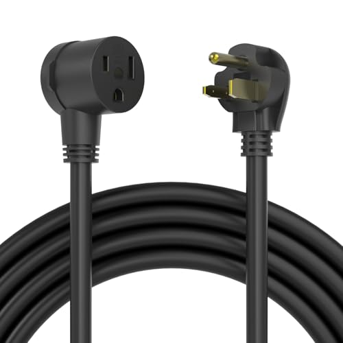
50FT CORD LENGTH: Safely extend your power up to 50 ft away, which may be combined with your existing welder cords and adapters, protecting you and others from hazardous welder spark.

Eco-Friendly Material : SJTW eco-friendly weatherproof material, odorless, corrosion-resistant & anti-aging, meets industrial safety standards; 12AWG 3-prong pure copper, 25A/250V/6250W, NEMA 6-50P to 6-50R, Perfect for Miller, Lincoln, MIG welders, optimized for light-medium welding tasks
The MIG Welder Has No Power
If the machine has no lights, display, or fan, verify that its input-voltage rating matches the outlet. Check the plug, receptacle, breaker, disconnect, and visible power-cord condition. Do not keep resetting a breaker that trips again.
An extension cord can also cause low input voltage if it is too long, undersized, damaged, or not approved for the welder’s input current. Follow the cord requirements in the owner’s manual rather than choosing one by guesswork.
Stop if you smell burned insulation, see melted parts, hear internal arcing, or find a damaged case. Those conditions require qualified service.
The Welder Runs and Then Shuts Down
A thermal-protection light usually means the machine has exceeded its duty cycle or cannot cool correctly. Leave the welder powered as directed by its manual so the fan can cool it, and wait for the thermal indicator to reset.
Clean blocked vents only after following the manufacturer’s shutdown instructions. Make sure the welder has open space around its air inlets and outlets. Repeated shutdown at light output can point to low input voltage, fan failure, heavy dust buildup, or an internal problem.
The Trigger Is Pulled but No Wire Feeds
Confirm that the gun connector is fully seated and that the trigger lead has not pulled loose. Check for a thermal-overload indicator because some machines disable weld output while overheated.
With input power disconnected, inspect the spool, inlet guide, drive roll, pressure arm, and wire path. A spool that is overtightened or tangled can stop feeding. If the drive motor turns but the wire does not move, check roll size, groove position, tension, and contact-tip blockage.
If the feeder motor remains silent after the gun connection, trigger, thermal status, and visible wire path have been checked, use the service procedure in the manual or arrange qualified repair.
Erratic Arc or No Arc at All
Start with the work clamp, often called the ground clamp. It carries welding current back to the machine; it is not a substitute for the building’s protective electrical ground. Clamp it to clean, bare base metal or a clean welding table with a sound electrical path to the part.
Inspect the work lead for cuts, overheated connectors, loose lugs, and broken strands. Put the clamp reasonably close to the weld when practical, and avoid routing welding current through bearings, hinges, chains, or electronic equipment.
Next, check polarity. Solid-wire GMAW commonly uses electrode-positive polarity, while many self-shielded flux-cored wires use electrode-negative polarity. The filler-metal data sheet and welder manual control; never assume all cored wires use the same polarity.
Replace a burned, loose, heavily worn, or obstructed contact tip. For steel wire, the nominal tip normally matches the wire diameter, but aluminum and high-temperature applications may require a purpose-made or slightly oversized tip. Follow the gun and wire manufacturer’s chart. Hobart explains the selection factors in its guide to choosing the correct contact tip.
Set voltage and wire-feed speed from the chart inside the welder, its manual, or the filler-metal data sheet. Those settings must work as a pair. Test on clean scrap of the same material, thickness, joint type, and position before welding the final part.
Wire-Feed Problems and Birdnesting
Wire feeding should remain steady from the spool to the contact tip. Start at the spool and work forward so you do not replace parts before finding the actual restriction.
- Spool and hub: Confirm that the wire comes off the spool in the direction shown by the manual. Set only enough hub tension to prevent the spool from overrunning when feeding stops.
- Drive-roll size: The groove must match the wire diameter.
- Drive-roll style: Smooth V-groove rolls are common for solid steel wire, U-groove rolls help protect soft aluminum wire, and knurled rolls are used for many tubular wires. Follow the wire and feeder instructions.
- Roll tension: Too little tension lets the wire slip. Too much can flatten, shave, or deform it and push debris into the liner.
- Gun cable: Keep it as straight as practical during testing. Tight loops and sharp bends increase drag.
- Liner: Check that its type, diameter, length, and trimming match the gun and wire. Replace a kinked, worn, damaged, or persistently blocked liner.
- Contact tip: Replace a tip with an oblong bore, fused spatter, poor fit, or repeated burnback.
Hobart’s wire-feeding guidance identifies drive rolls, liner condition, tip wear, and gun-cable length or routing as common causes. If your gun manufacturer permits compressed-air cleaning, disconnect the gun and follow its instructions. Wear eye protection and direct debris away from people and equipment.
Pro Tip
When testing drive-roll tension, use the method in your feeder manual. The goal is enough force to feed consistently without crushing or shaving the wire. Tightening the pressure knob as far as it will go often makes feeding problems worse.
Shielding-Gas Problems and Porosity
Porosity can look like visible pinholes, worm tracks, or internal cavities found after grinding or inspection. Check whether shielding gas reaches the nozzle while the trigger is held. A regulator reading alone does not prove that gas is reaching the weld.
- Confirm that the cylinder valve is open and the cylinder contains usable pressure.
- Set flow while gas is moving, following the welder, regulator, and filler-metal instructions.
- Check fittings, O-rings, hose, solenoid connections, and the gun connection with an approved leak-detection solution.
- Never use a flame to find a gas leak.
- Clean spatter from the nozzle and diffuser without damaging the gas passages.
- Protect the weld from fans, open doors, wind, and compressed-air discharge.
- Do not assume more flow is always better. Excess flow can create turbulence and draw surrounding air into the gas shield.
- Clean the joint and nearby metal of oil, paint, rust, moisture, and coatings.
- Allow cold material and wire to warm without condensation before welding.
A 75% argon/25% CO2 blend is common for short-circuit MIG welding on mild steel, but gas and flow depend on the wire, transfer mode, joint, nozzle, and procedure. Aluminum MIG commonly uses argon. Stainless-steel gas selection varies with the wire, transfer mode, and required weld properties, so use the filler-metal data sheet rather than treating one tri-mix as universal.
Wire Burns Back Into the Contact Tip
Burnback happens when the arc travels up the wire and fuses it to the contact tip. It often follows interrupted feeding, wire-feed speed that is too low for the selected voltage, excessive wire resistance, a worn tip, an incorrect tip, or holding the gun too close.
For short-circuit MIG, a contact-tip-to-work distance around 3/8 to 1/2 inch is a common guideline, but the correct distance depends on the process and gun setup. Bernard and Tregaskiss explain the difference between electrode stick-out and contact-tip-to-work distance.
If burnback repeats, replace the damaged tip and find the cause before trying again. Check the spool brake, rolls, tension, liner, cable bends, tip size, wire condition, wire-feed speed, voltage, and any adjustable burnback control described in the manual.
Excessive Spatter or a Harsh Arc
Spatter does not come from one setting alone. Common causes include voltage and wire-feed speed that are out of balance, incorrect polarity, long or inconsistent stick-out, contamination, an unstable work connection, poor wire feeding, the wrong shielding gas, or an unsuitable transfer mode.
Return to the machine chart, clean the joint, verify polarity, and keep gun distance and travel speed steady. Change one setting at a time on scrap so you can see what helped.
Anti-spatter products can reduce buildup on the nozzle or metal beside the joint. Do not coat the weld joint or contaminate surfaces that must fuse, be painted, or receive another finish. Follow the product safety data sheet and the welding procedure.
Burn-Through, Lack of Fusion, and Poor Bead Shape
Burn-through usually means the joint receives more heat than the material can handle. Possible causes include settings that are too hot, travel that is too slow, excessive gaps, poor fit-up, thin edges, or too much repeated welding in one area.
Lack of fusion can come from settings that are too cold, travel that is too fast, poor gun angle, a long CTWD, contamination, or a joint design that blocks access to the root. A bead that sits high without tying into both sides of the joint needs correction even if its surface looks smooth.
Use the machine chart and a test coupon instead of a universal voltage range. For a critical joint, follow an approved welding procedure and required inspection or testing.
Step-by-Step MIG Welder Troubleshooting Guide
- Identify the exact symptom. Separate no power, no feed, no gas, no arc, unstable arc, porosity, burnback, spatter, poor fusion, and thermal shutdown.
- Make the area safe. Remove combustibles, secure the cylinder, wear PPE, and disconnect power before mechanical or internal inspection.
- Verify input power. Check the supply rating, outlet, breaker, plug, cord, extension cord, and thermal indicator.
- Check the work circuit. Attach the work clamp to clean metal and inspect the lead and connectors.
- Confirm polarity and process. Match the polarity, wire, gas, drive roll, liner, and contact tip to the filler-metal instructions.
- Inspect the spool and feed path. Check spool drag, roll groove, roll pressure, inlet guide, gun cable, liner, and contact tip.
- Verify shielding gas. Confirm flow at the nozzle, inspect for leaks or restrictions, clean the nozzle and diffuser, and block drafts.
- Load starting parameters. Use the machine chart, manual, wire data sheet, or qualified welding procedure.
- Test on matching scrap. Keep CTWD, angle, travel speed, and joint fit-up consistent. Change one variable at a time.
- Stop at the service boundary. Arrange qualified repair for internal electrical damage, persistent control faults, repeated breaker trips, gas-regulator damage, or a dead feeder motor that external checks do not explain.
MIG Welder Troubleshooting Chart
| Issue | Symptoms | Possible Causes | Corrective Checks |
|---|---|---|---|
| No power | No lights, display, or fan | Supply, breaker, plug, cord, voltage mismatch | Verify the rated supply and visible input components; stop after repeated trips |
| No wire feed | Trigger does nothing or motor turns without moving wire | Trigger, gun plug, spool, rolls, tip, thermal protection | Seat the gun, cool the machine, and inspect the de-energized feed path |
| Erratic or no arc | Stuttering, flaring, stubbing, or no arc | Poor work connection, polarity, tip, feeding, settings | Clean and secure the work circuit; verify polarity and starting parameters |
| Jerky feeding | Wire surges, slips, or birdnests | Spool drag, roll mismatch, tension, liner, cable bends | Correct the spool, roll, pressure, liner, tip, and cable route |
| Porosity | Pinholes, cavities, worm tracks | Gas loss, leak, draft, excess flow, contamination, moisture | Measure flow while gas moves; fix leaks and clean and dry the joint |
| Burnback | Wire fuses inside contact tip | Feed interruption, low WFS, short CTWD, tip or liner trouble | Replace the tip and correct the feed path, settings, and gun distance |
| Excessive spatter | Droplets around weld and harsh sound | Parameter imbalance, polarity, contamination, CTWD, poor feed | Return to the chart and verify the entire electrical and feed setup |
| Thermal shutdown | Output stops and thermal light appears | Duty cycle, blocked vents, low voltage, cooling fault | Allow cooling, clear airflow, and compare operation with the manual |
Choosing the Correct Wire, Gas, and Consumables
Products Worth Considering

High-quality: ARCCAPTAIN's ER70S-6 mig welding wire .035" meets industry standards(Net Weight: 10lbs), ensuring consistent performance, superior strength. With its smooth feeding and stable welding parameters, you can achieve optimal penetration, high deposition rates, and exceptional overall welding performance.

ER70S-6 MIG WIRE: It's the most common wire of the copper-coated mild steel GMAW (MIG) wires for single or multiple pass welding.

High-quality: ARCCAPTAIN's ER70S-6 mig welding wire .030" meets industry standards(Net Weight: 10lbs), ensuring consistent performance, superior strength. With its smooth feeding and stable welding parameters, you can achieve optimal penetration, high deposition rates, and exceptional overall welding performance.
Wire Selection
Mild steel: ER70S-6 solid wire is common because its deoxidizers help it tolerate light mill scale better than some alternatives, but the base metal, joint, required properties, process, and welding procedure still control filler selection. Choose a diameter that operates comfortably within the welder’s rated output and the required deposition range.
Aluminum: ER4043 and ER5356 are common, but neither is correct for every alloy or service condition. ER4043 can offer good flow and reduced cracking sensitivity in suitable joints. ER5356 can provide higher strength, ductility, or anodized color matching in suitable 5xxx- and 6xxx-series applications. Elevated service temperature, base-alloy compatibility, corrosion, and the qualified procedure also matter. Miller’s aluminum filler guidance explains these tradeoffs.
Soft aluminum wire may require a spool gun, push-pull system, U-groove rolls, a suitable nonmetallic liner, and aluminum-specific contact tips. See Miller’s guide to MIG welding aluminum.
Stainless steel: ER308L is commonly used for suitable 304-series stainless applications, but stainless filler must match the base grade, dilution, corrosion exposure, service temperature, and procedure. Do not choose it by appearance alone.
Shielding-Gas Selection
- Mild steel: A 75/25 argon/CO2 blend is common for short-circuit work. CO2 and other argon-rich blends have different penetration, transfer, and spatter characteristics.
- Aluminum: Argon is common, while argon-helium blends may be used for some thicker or specialized work.
- Stainless steel: The correct blend depends on the transfer mode, filler wire, base alloy, and required corrosion and mechanical properties.
Use the filler-metal data sheet and welding procedure for gas type and flow. The number shown on a flowmeter should be confirmed while gas is moving, and it may not equal the flow reaching the nozzle if the system leaks or is restricted.
Machine and Gun Requirements
Choose equipment by capability rather than brand name alone. Check input power, output range, duty cycle, wire-size capacity, polarity changeover, drive-roll availability, gun rating, consumable availability, and local service support.
For aluminum, confirm that the machine supports the intended spool gun or push-pull system. For long production welds, make sure the gun and power source can carry the required current without exceeding their duty-cycle ratings.
Safety Considerations
Arc welding exposes your eyes and skin to ultraviolet and infrared radiation. Use a welding helmet and filter shade selected for the actual process and current, along with safety glasses that provide side protection. OSHA requires suitable eye and face protection for arc welding and protective clothing appropriate to the work. Review OSHA 29 CFR 1910.252 and your helmet instructions.
Wear dry welding gloves, flame-resistant clothing, and protective footwear. Cover exposed skin and keep cables out of walkways. Replace damaged insulation, connectors, and electrode holders or guns before use.
Keep welding fumes out of your breathing zone. Stainless steel can create chromium- and nickel-containing fumes, and heated zinc coatings can produce zinc oxide. Paint, solvents, degreasers, plating, and unknown coatings can introduce additional hazards. Use source capture or suitable ventilation and obtain professional exposure-control advice when the material or coating is uncertain.
Never use oxygen for ventilation. Protect nearby people from arc rays with suitable screens, and maintain a fire watch when the work or surroundings require one.
Maintenance That Prevents Repeat Problems
- Inspect the gun, work lead, power cord, plug, connectors, and gas hose before use.
- Remove nozzle spatter before it blocks gas flow or electrically bridges the nozzle and tip.
- Replace contact tips when the bore wears, feeding becomes unstable, or burnback damages the tip.
- Keep wire covered, clean, and dry. Replace rusty, dirty, kinked, or contaminated wire.
- Clean drive rolls and guides without damaging their grooves.
- Inspect and service the liner at the interval and by the method stated by the gun manufacturer.
- Keep cooling vents clear and maintain open airflow around the machine.
- Check cylinder restraints, regulators, hoses, fittings, and O-rings regularly.
- Record successful settings for repeat jobs only after confirming the material, joint, wire, gas, position, and machine are the same.
Practical Tips for Better MIG Welding
Prepare the joint: Remove oil, paint, rust, moisture, heavy mill scale, and coatings that interfere with the procedure. Keep grinding debris away from the wire feeder and gas equipment.
Test before committing: Use clean scrap of the same material and thickness. A scrap weld on different metal does not prove the final setup is correct.
Keep CTWD consistent: A common short-circuit reference is about 3/8 to 1/2 inch, but the correct distance comes from the process and procedure.
Listen and look: A stable short-circuit arc often sounds steady, but sound alone cannot confirm penetration, fusion, or internal quality.
Change one variable at a time: If you adjust voltage, wire-feed speed, gas, angle, and travel speed together, you will not know which change corrected the problem.
Real-World Applications and When DIY Troubleshooting Stops
The same diagnostic sequence works for many shop jobs, including a lawnmower bracket, barbecue frame, sheet-metal panel, cart, gate, or general repair. Thin material usually needs careful fit-up, controlled heat input, and short weld sequences. Thicker joints may require more output, joint preparation, multiple passes, or a different machine.
Do not assume that increasing voltage alone creates safe penetration. Joint design, root opening, bevel, wire, gas, position, travel speed, preheat, technique, and procedure all affect fusion.
Structural members, pressure parts, lifting points, suspension components, roll cages, steering parts, trailers, and other safety-critical assemblies may require a qualified welding procedure, certified welder, inspection, or destructive and nondestructive testing. Use a qualified professional when failure could injure someone.
Conclusion
A MIG welder that is not working should be diagnosed from the symptom backward. Check safe input power, the work connection, polarity, spool, drive rolls, liner, contact tip, shielding gas, and starting parameters before replacing major parts. Most external setup problems can be corrected methodically, but burned wiring, repeated breaker trips, gas-equipment damage, and internal control faults belong with qualified service personnel.
FAQ
Why Is My MIG Welder Not Feeding Wire Properly?
Jerky or stopped feeding often comes from spool drag, the wrong drive roll, incorrect roll tension, a kinked or dirty liner, a worn contact tip, sharp gun-cable bends, or a trigger fault. Disconnect input power before inspecting the mechanical feed path. Match the roll, liner, and tip to the wire type and diameter.
How Do I Fix Porosity in MIG Welds?
Confirm that the correct gas reaches the nozzle while the trigger is held. Check for leaks, blocked gas passages, drafts, excessive flow, low flow, moisture, and surface contamination. Clean and dry the joint, repair leaks with approved parts, and use the gas and flow stated by the welder, regulator, wire manufacturer, or welding procedure.
What Settings Should I Use for MIG Welding Mild Steel?
Use the chart inside your welder, its manual, or the filler-metal data sheet. The correct voltage and wire-feed speed depend on material thickness, wire diameter, shielding gas, joint, position, transfer mode, and machine design. Test on matching scrap and adjust one variable at a time.
Why Does My MIG Welder Keep Burning Back?
Repeated burnback usually means the wire is feeding too slowly or inconsistently for the selected voltage, the gun is too close, the tip is worn or incorrectly sized, or resistance exists at the spool, drive rolls, liner, cable, or contact tip. Replace the damaged tip, correct the feed problem, and reset the machine from its chart.
How Often Should I Maintain My MIG Welder?
Follow the intervals in the owner’s manual and adjust them for wire use, dust, heat, humidity, and production time. Inspect cables, the gun, work clamp, gas hose, and consumables before use. Clean or replace feed-path parts when inspection, feeding behavior, or the manufacturer’s schedule shows that service is needed.
Sources
- American Welding Society — ANSI Z49.1:2021, Safety in Welding, Cutting, and Allied Processes
- OSHA — 29 CFR 1910.252, General Welding, Cutting, and Brazing Requirements
- Lincoln Electric — MIG Problems and Remedies
- Miller — Setting the Correct MIG Welding Parameters
- Hobart Brothers — Common Causes of Wire-Feeding Problems
- Bernard and Tregaskiss — MIG Welding Techniques and CTWD




